How to distinguish whether the tube in your hand is N tube or P tube?
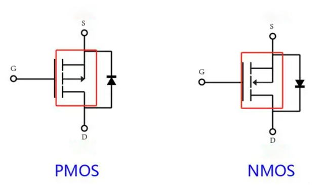
First, let's take the enhancement MOS tube as an example. This is the circuit symbol of the two:

You can see that the directions of the two arrows are inconsistent.
This arrow is its substrate, because the internal substrate and source of the MOS tube are connected together.
The biggest difference between the NMOS and PMOS circuit symbols lies in its substrate. The arrow of NMOS points to the gate, while the arrow of PMOS points back to the gate.
The direction of this arrow is related to the direction of the PN junction between the internal substrate and the channel inversion layer of the MOS tube.
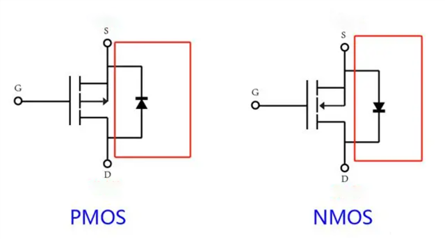
Secondly, the body diodes of NMOS and PMOS are opposite.
The anode (i.e. positive pole) of the body diode of the NMOS tube is connected to the source, the anode of the body diode of the PMOS is connected to the drain, and the negative pole of the body diode is connected to the source.

So, how to distinguish the three pins of the MOS tube?
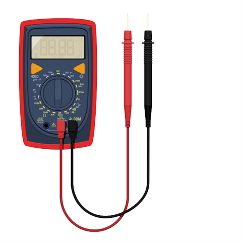
You can use a multimeter to test it. Here is a brief explanation.

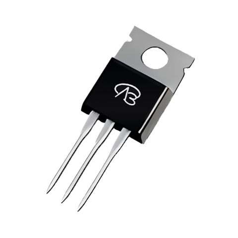
Take a MOS tube packaged as TO220, which usually has a heat sink, and the heat sink will be connected to the drain. Use a multimeter to test which pin can be connected to the heat sink, which corresponds to the drain.

Because of the connection of the diode, there are diode characteristics between the drain and the source.
Therefore, when using a multimeter to test the drain and which pin can be connected in both forward and reverse directions, it is the source.
The rest is the gate.
In summary, there are two points:
1. The positive pole of the NMOS diode is generally connected to the source
2. The heat sink is connected to the drain
