

Other Parts Discussed in Thread: MSPM0L1306, SYSCONFIG
请注意,本文内容源自机器翻译,可能存在语法或其它翻译错误,仅供参考。如需获取准确内容,请参阅链接中的英语原文或自行翻译。
器件型号:MSPM0L1306主题: SysConfig 中讨论的其他器件
工具/软件:
你(们)好
我有一个针对 MSPM0L1306 的固件工程。 该固件会在不同时间将某些 MCU 引脚重新连接到不同的 MCU 外设。 例如、在某些情况下、MCU 引脚用作 SPI 外设引脚、有时则用作具有中断功能的中断 GPIO。 我能够更改引脚的功能、串行接口(SPI、I2C 等)可以正常工作、但捕捉输入中断的问题更大。
为了简化这个问题、我生成了一个最小的工作示例。 在这里、我只需要在支持中断的输入引脚上检测到上升沿条件时检测何时调用 GPIO ISR。 不实现引脚功能、也不使用低功耗模式状态。
以下是我们的 SysConfig 文件的内容:
/**
 * These arguments were used when this file was generated. They will be automatically applied on subsequent loads
 * via the GUI or CLI. Run CLI with '--help' for additional information on how to override these arguments.
 * @cliArgs --device "MSPM0L130X" --part "Default" --package "VQFN-32(RHB)" --product "mspm0_sdk@2.05.01.01"
 * @v2CliArgs --device "MSPM0L1306" --package "VQFN-32(RHB)" --product "mspm0_sdk@2.05.01.01"
 * @versions {"tool":"1.24.0+4150"}
 */

/**
 * Import the modules used in this configuration.
 */
const GPIO          = scripting.addModule("/ti/driverlib/GPIO", {}, false);
const GPIO1         = GPIO.addInstance();
const SYSCTL        = scripting.addModule("/ti/driverlib/SYSCTL");
const ProjectConfig = scripting.addModule("/ti/project_config/ProjectConfig");

/**
 * Write custom configuration values to the imported modules.
 */
GPIO1.$name                         = "GPIO_GRP_EXAMPLE_TEST";
GPIO1.associatedPins.create(3);
GPIO1.associatedPins[0].direction   = "INPUT";
GPIO1.associatedPins[0].fastWakeEn  = true;
GPIO1.associatedPins[0].interruptEn = true;
GPIO1.associatedPins[0].polarity    = "RISE";
GPIO1.associatedPins[0].$name       = "PIN_INTERRUPT_CAPABLE_INPUT";
GPIO1.associatedPins[1].$name       = "PIN_INTERRUPT_ACTIVITY";
GPIO1.associatedPins[1].pin.$assign = "PA1";
GPIO1.associatedPins[2].$name       = "PIN_CONTROL";

const Board                       = scripting.addModule("/ti/driverlib/Board", {}, false);
Board.peripheral.$assign          = "DEBUGSS";
Board.peripheral.swclkPin.$assign = "PA20";
Board.peripheral.swdioPin.$assign = "PA19";

SYSCTL.peripheral.$assign = "SYSCTL";

ProjectConfig.migrationCondition = true;

/**
 * Pinmux solution for unlocked pins/peripherals. This ensures that minor changes to the automatic solver in a future
 * version of the tool will not impact the pinmux you originally saw.  These lines can be completely deleted in order to
 * re-solve from scratch.
 */
GPIO1.associatedPins[0].pin.$suggestSolution = "PA0";
GPIO1.associatedPins[2].pin.$suggestSolution = "PA2";
在这里、我实例化了 3 个 GPIO 引脚:
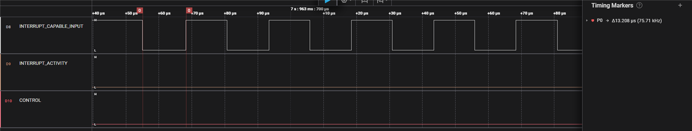
- PIN_INTERRUPT_CAPABLE_INPUT 是支持中断的输入引脚、应在上升沿触发中断
- PIN_INTERRUPT_ACTIVITY 是一个输出引脚、用于指示我何时在 ISR 内
- PIN_CONTROL 是一个输出引脚、用于向外部器件发送信号、以开始在 PIN_INTERRUPT_CAPABLE_INPUT 上生成活动
主程序如下所示:
#include "ti_msp_dl_config.h"

int main(void)
{
    SYSCFG_DL_init();

    NVIC_EnableIRQ(GPIO_GRP_EXAMPLE_TEST_INT_IRQN);

    while (1) {
    }
}

void GROUP1_IRQHandler(void)
{
    DL_GPIO_setPins(GPIO_GRP_EXAMPLE_TEST_PORT, GPIO_GRP_EXAMPLE_TEST_PIN_INTERRUPT_ACTIVITY_PIN);

    DL_GPIO_clearPins(GPIO_GRP_EXAMPLE_TEST_PORT, GPIO_GRP_EXAMPLE_TEST_PIN_INTERRUPT_ACTIVITY_PIN);
}
引脚配置由 SYSCFG_DL_init () 完成。 我的 ISR 所做的就是、当输入 该命令后、设置 PIN_INTERRUPT_ACTIVITY、然后间接地将其清除。
如果我通过-O0 优化运行该软件、可以看到 PIN_INTERRUPT_ACTIVATE_INPUT 的上升沿切换 PIN_INTERRUPT_CAPABLE_INPUT。

如果我运行同一软件进行-O2 优化、PIN_INTERRUPT_ACTIVITY 不会在 PIN_INTERRUPT_CAPABLE_INPUT 上升沿上切换。
我正在使用 CCS 12.8-1、MSPM0 SDK 2.5.1 和 SysConfig 1.24。 我没想到会出现这种情况。 我如何确保在上升沿 GPIO 输入上以-O2 或-O3 优化来调用 GPIO ISR?
谢谢
