

请注意,本文内容源自机器翻译,可能存在语法或其它翻译错误,仅供参考。如需获取准确内容,请参阅链接中的英语原文或自行翻译。
器件型号:EK-TM4C1294XL 主题中讨论的其他器件: MSP430FR2355
大家好、团队、
我们正在研究 UART3接收和 UDMA、其中 EK-TM4C1294XL (Launchpad)作为主器件、MSP430FR2355作为小器件(从 TM4C 接收数据包并发送到 TM4C)。 因此、我已经为 UDMA 接收通道配置了 UART3。此外、我们还在主从设备之间对 Tx 和 Rx 使用 RS485、但每当我在 UDMA 接收步骤处保留断点时、数据都会逐字节获取。 但在自由运行时、没有数据到达我的内部缓冲区。 为什么会发生这种情况、与之前一样、在使用 TM4C (Launchpad)和 MSP430FR2355 (Launchpad)使用 UART0时、我也遇到了这种问题。 但与 UART3目前使用的配置类型相同。 UART3至 UART0是否有任何更改在设计中添加了 RS485? 请帮助我解决问题。 我在 uDMA 中面临着很多问题。 能不能有人告诉我为什么会这样发生?任何帮助都是非常感激的。
 void Init_UART3_UDMA()
{
 // Enable the uDMA controller at the system level.  Enable it to continue
    // to run while the processor is in sleep.
    //
    ROM_SysCtlPeripheralEnable(SYSCTL_PERIPH_UDMA);
    ROM_SysCtlPeripheralSleepEnable(SYSCTL_PERIPH_UDMA);

    //
    // Enable the uDMA controller error interrupt.  This interrupt will occur
    // if there is a bus error during a transfer.
    //
    ROM_IntEnable(INT_UDMAERR);

    //
    // Enable the uDMA controller.
    //
    ROM_uDMAEnable();

    //
    // Point at the control table to use for channel control structures.
    //
    ROM_uDMAControlBaseSet(pui8ControlTable);


    //
    // Enable the GPIO Peripheral used by the UART.
    //
    SysCtlPeripheralEnable(SYSCTL_PERIPH_GPIOA);

    //
    // Enable UART0.
    //
    SysCtlPeripheralEnable(SYSCTL_PERIPH_UART3);

    //
    // Enable processor interrupts.
    //
    IntMasterEnable();

    //
    // Configure GPIO Pins for UART mode.
    //
    GPIOPinConfigure(GPIO_PA4_U3RX);
    GPIOPinConfigure(GPIO_PA5_U3TX);
    GPIOPinTypeUART(GPIO_PORTA_BASE, GPIO_PIN_4 | GPIO_PIN_5);

    //
    // Initialize the UART for console I/O.
    //
    //UARTStdioConfig(3, 1000000, g_ui32SysClock);
    UARTConfigSetExpClk(UART3_BASE, g_ui32SysClock, 1000000,
                        (UART_CONFIG_WLEN_8 | UART_CONFIG_STOP_ONE |
                        UART_CONFIG_PAR_NONE));

    // UART9BitAddrSend(UART0_BASE, 0x00);
    //  UART9BitEnable(UART0_BASE);

    UARTFIFOEnable(UART3_BASE);

    UARTFIFOLevelSet(UART3_BASE, UART_FIFO_TX4_8, UART_FIFO_RX4_8);

    //
    // Enable the UART for operation, and enable the uDMA interface for both TX
    // and RX channels.
    //
    // MAP_UARTEnable(UART0_BASE);
    MAP_UARTDMAEnable(UART3_BASE, UART_DMA_RX | UART_DMA_TX);

   // HWREG(UART3_BASE + UART_O_CTL) |= UART_CTL_LBE;

    //
    // Put the attributes in a known state for the uDMA UART1RX channel.  These
    // should already be disabled by default.
    //
    MAP_uDMAChannelAttributeDisable(UDMA_CH16_UART3RX,
    UDMA_ATTR_ALTSELECT | UDMA_ATTR_USEBURST |
    UDMA_ATTR_HIGH_PRIORITY |
    UDMA_ATTR_REQMASK);

    //
    // Configure the control parameters for the primary control structure for
    // the UART RX channel.  The primary contol structure is used for the "A"
    // part of the ping-pong receive.  The transfer data size is 8 bits, the
    // source address does not increment since it will be reading from a
    // register.  The destination address increment is byte 8-bit bytes.  The
    // arbitration size is set to 4 to match the RX FIFO trigger threshold.
    // The uDMA controller will use a 4 byte burst transfer if possible.  This
    // will be somewhat more effecient that single byte transfers.
    //
    MAP_uDMAChannelControlSet(UDMA_CH16_UART3RX | UDMA_PRI_SELECT,
    UDMA_SIZE_16 | UDMA_SRC_INC_NONE | UDMA_DST_INC_16);

    //
    // Configure the control parameters for the alternate control structure for
    // the UART RX channel.  The alternate contol structure is used for the "B"
    // part of the ping-pong receive.  The configuration is identical to the
    // primary/A control structure.
    //
    MAP_uDMAChannelControlSet(UDMA_CH16_UART3RX | UDMA_ALT_SELECT,
    UDMA_SIZE_16 | UDMA_SRC_INC_NONE | UDMA_DST_INC_16);

    MAP_uDMAChannelEnable(UDMA_CH16_UART3RX);
//    ROM_uDMAChannelRequest(UDMA_CH16_UART3RX);
    MAP_uDMAChannelEnable(UDMA_CH17_UART3TX);

    //
    // Enable the UART DMA TX/RX interrupts.
    //
    MAP_UARTIntEnable(UART3_BASE, UART_INT_DMARX | UART_INT_DMATX);

    MAP_UARTEnable(UART3_BASE);
    //
    // Enable the UART interrupt.
    //
    //IntEnable(INT_UART0);
    MAP_UARTIntEnable(UART3_BASE, UART_INT_RX | UART_INT_RT);
}

void uDMA_Receive()
{
//
// Get the interrupt status.
//
    ui32Status1 = MAP_UARTIntStatus(UART3_BASE, true);

//
// Clear the asserted interrupts.
//
    MAP_UARTIntClear(UART3_BASE, ui32Status1);

//
// Check the DMA control table to see if the Basic "gu8Array" transfer is
// complete.  The "gu8Array" transfer uses receive buffer "gu8Array", and
// the primary control structure.
//
    ui32Mode = ROM_uDMAChannelModeGet(
            UDMA_CH16_UART3RX | UDMA_PRI_SELECT);

//
// If the primary control structure indicates stop, that means the "gu8Array"
// receive buffer is done.
//
    if (ui32Mode == UDMA_MODE_STOP)
    {

        ROM_uDMAChannelTransferSet(
                UDMA_CH16_UART3RX | UDMA_PRI_SELECT,
                UDMA_MODE_BASIC,
                (void*) (UART3_BASE + (uint16_t) (UART_O_DR & 0xFFFF)),
                gu8Array, sizeof(gu8Array));

        ROM_uDMAChannelEnable(UDMA_CH16_UART3RX);
        ROM_uDMAChannelRequest(UDMA_CH16_UART3RX);

    }
}
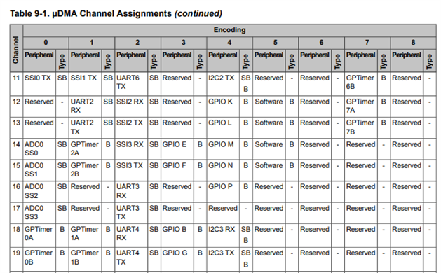
如上图所示、UART3和通道16、17位于外设2

上图 UART0和通道8、9作为外设0。
与 UART0相比,使用 UDMA 接收 UART3的配置是否出错,或者是否可以使用相同的配置;使用 UDMA 接收 UART0? 请参阅代码并指导我正确使用 uDMA 接收数据。
