This thread has been locked.

If you have a related question, please click the "Ask a related question" button in the top right corner. The newly created question will be automatically linked to this question.

[参考译文] EK-TM4C123GXL:无法使用 I2C

Guru**** 2337880 points
Other Parts Discussed in Thread: TM4C123GH6PM, ENERGIA
请注意,本文内容源自机器翻译,可能存在语法或其它翻译错误,仅供参考。如需获取准确内容,请参阅链接中的英语原文或自行翻译。

https://e2e.ti.com/support/microcontrollers/arm-based-microcontrollers-group/arm-based-microcontrollers/f/arm-based-microcontrollers-forum/998179/ek-tm4c123gxl-failing-to-use-i2c

器件型号:EK-TM4C123GXL
主题中讨论的其他器件:TM4C123GH6PMTM4C123ENERGIA

您好!

我尝试通过 I2C 传输数据。 但是、我似乎无法使它正常工作。

使用 CCS 版本10.3.0.00007,我在 TI 提供的外设用户指南的16.3下复制了编程示例,请参阅链接:

www.ti.com/.../spmu298e.pdf

我将随附我的代码:

#include <stdint.h>
#include <stdbool.h>
#include "inc/hw_ints.h"
#include "inc/hw_memmap.h"
#include "inc/hw_types.h"
#include "driverlib/debug.h"
#include "driverlib/fpu.h"
#include "driverlib/gpio.h"
#include "driverlib/interrupt.h"
#include "driverlib/pin_map.h"
#include "driverlib/rom.h"
#include "driverlib/sysctl.h"
#include "driverlib/timer.h"
#include "driverlib/i2c.h"

//*****************************************************************************
//
// The error routine that is called if the driver library encounters an error.
//
//*****************************************************************************
#ifdef DEBUG
void
__error__(char *pcFilename, uint32_t ui32Line)
{
}
#endif

void ConfigureI2CasMaster()
{
SysCtlPeripheralEnable(SYSCTL_PERIPH_I2C0);

while (!SysCtlPeripheralReady(SYSCTL_PERIPH_I2C0))
{

}

// set bus speed and enable master
I2CMasterInitExpClk(I2C0_BASE, SysCtlClockGet(), true);

I2CMasterSlaveAddrSet(I2C0_BASE, 0x3B, false);

I2CMasterDataPut(I2C0_BASE, 'Q');

I2CMasterControl(I2C0_BASE, I2C_MASTER_CMD_SINGLE_SEND);

while (I2CMasterBusBusy(I2C0_BASE))
{

}

}

void SendI2CData()
{

I2CMasterDataPut(I2C0_BASE, 'Q');

I2CMasterControl(I2C0_BASE, I2C_MASTER_CMD_SINGLE_SEND);

while (I2CMasterBusBusy(I2C0_BASE))
{

}

}

//*****************************************************************************
//
// main
//
//*****************************************************************************

int main(void)
{
// Setup the system clock to run at 40 MHz from PLL with crystal reference
ROM_SysCtlClockSet(SYSCTL_SYSDIV_5 | SYSCTL_USE_PLL | SYSCTL_XTAL_16MHZ |
SYSCTL_OSC_MAIN);

ConfigureI2CasMaster();

// enter the Loop
while (1)
{
SysCtlDelay(10000);
SendI2CData();
}
}

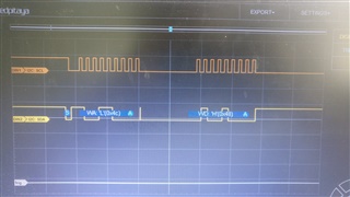
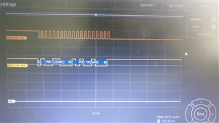
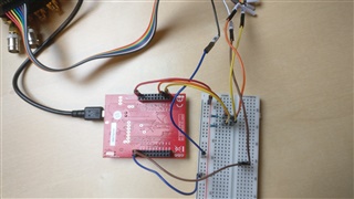
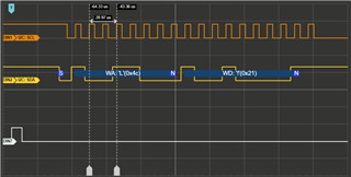
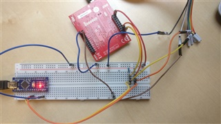
我在引脚 B2和 B3上有一个逻辑分析仪、这是 TM4C123GXL 板上的 SCL0和 SDA0。

GND 已连接、逻辑分析仪已正确设置。  (在不同器件上测试)

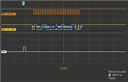
我希望我的代码能够重复传输数据、但我的逻辑分析仪却显示完全没有发生任何事情。

我的代码有什么问题吗?

谢谢你

  • 请注意,本文内容源自机器翻译,可能存在语法或其它翻译错误,仅供参考。如需获取准确内容,请参阅链接中的英语原文或自行翻译。
    [引用 userid="484273" URL"~/support/microcontrollers/other/f/other-microcontrollers-forum/998179/ek-tm4c123gxl-failing-to-use-i2c "]我在引脚 B2和 B3上有一个逻辑分析仪,这两个引脚是 TM4C123GXL 电路板上的 SCL0和 SDA0 [/引用]

    在发布的代码中、我看不到任何将 B2和 B3引脚设置为由 I2C0外设控制的调用。 而 表10-2.   TM4C123GH6PM 数据表中的 GPIO 引脚和备用功能(64LQFP)显示  了 I2C0SCL 和 I2C0SDA 的引脚多路复用器的 PB2和 PB3默认值、 TivaWare_C_Series-2.2.0.295/examples/peripherals/i2c/master_slave_loopback。c 显示了以下调用、用于配置和启用 I2C PeripheralB2 (0)外设:

        //
        // The I2C0 peripheral must be enabled before use.
        //
        SysCtlPeripheralEnable(SYSCTL_PERIPH_I2C0);
    
        //
        // For this example I2C0 is used with PortB[3:2].  The actual port and
        // pins used may be different on your part, consult the data sheet for
        // more information.  GPIO port B needs to be enabled so these pins can
        // be used.
        // TODO: change this to whichever GPIO port you are using.
        //
        SysCtlPeripheralEnable(SYSCTL_PERIPH_GPIOB);
    
        //
        // Configure the pin muxing for I2C0 functions on port B2 and B3.
        // This step is not necessary if your part does not support pin muxing.
        // TODO: change this to select the port/pin you are using.
        //
        GPIOPinConfigure(GPIO_PB2_I2C0SCL);
        GPIOPinConfigure(GPIO_PB3_I2C0SDA);
    
        //
        // Select the I2C function for these pins.  This function will also
        // configure the GPIO pins pins for I2C operation, setting them to
        // open-drain operation with weak pull-ups.  Consult the data sheet
        // to see which functions are allocated per pin.
        // TODO: change this to select the port/pin you are using.
        //
        GPIOPinTypeI2CSCL(GPIO_PORTB_BASE, GPIO_PIN_2);
        GPIOPinTypeI2C(GPIO_PORTB_BASE, GPIO_PIN_3);
    您能否尝试将来自 TivaWare 示例的上述调用添加到您的代码中、以查看是否在引脚上生成了 I2C 活动?

    还假设硬件在 SCL 和 SDA 信号上有上拉电阻器。

  • 请注意,本文内容源自机器翻译,可能存在语法或其它翻译错误,仅供参考。如需获取准确内容,请参阅链接中的英语原文或自行翻译。

    您好!

     切斯特正确地说、您没有配置 I2C 引脚。  您参考的 C:\ti\TivaWare_C_Series-2.2.0.295\examples\peripherals\i2c 中有多个示例、 以及 C:\ti\TivaWare_C_Series-2.2.0.295\examples\boards\ek-tm4c123gxl-boostxl-shenb\simple 可立即导入到 CCS 中的完整 CCS 项目。  

  • 请注意,本文内容源自机器翻译,可能存在语法或其它翻译错误,仅供参考。如需获取准确内容,请参阅链接中的英语原文或自行翻译。

    谢谢你们!

  • 请注意,本文内容源自机器翻译,可能存在语法或其它翻译错误,仅供参考。如需获取准确内容,请参阅链接中的英语原文或自行翻译。

    我偶然发现了另一件我不知道如何解决的事情:

    我正在尝试在每个事务中发送多个字节的信息。

    现在、我可以发送一个字节(首先是地址字节、然后是信息字节)、但我需要发送更多字节(地址、命令和两个值)

    我尝试了以下操作,但没有成功:

    #include <stdint.h>
    #include <stdbool.h>
    #include "inc/hw_i2c.h"
    #include "inc/hw_ints.h"
    #include "inc/hw_memmap.h"
    #include "inc/hw_types.h"
    #include "driverlib/debug.h"
    #include "driverlib/fpu.h"
    #include "driverlib/gpio.h"
    #include "driverlib/interrupt.h"
    #include "driverlib/pin_map.h"
    #include "driverlib/rom.h"
    #include "driverlib/sysctl.h"
    #include "driverlib/timer.h"
    #include "driverlib/i2c.h"
    
    //*****************************************************************************
    //
    // The error routine that is called if the driver library encounters an error.
    //
    //*****************************************************************************
    #ifdef DEBUG
    void
    __error__(char *pcFilename, uint32_t ui32Line)
    {
    }
    #endif
    
    void ConfigureI2CasMaster()
    {
    //
    // enable I2C0 Peripheral
        SysCtlPeripheralEnable(SYSCTL_PERIPH_I2C1);
    
    //
    // wait until it's enabled
        while (!SysCtlPeripheralReady(SYSCTL_PERIPH_I2C1))
        {
        }
    
    //
    // enable GPIO Port B
        SysCtlPeripheralEnable(SYSCTL_PERIPH_GPIOA);
    
    //
    // wait until it's enabled
        while (!SysCtlPeripheralReady(SYSCTL_PERIPH_GPIOA))
        {
        }
    
    //
    // Configure the pin muxing for I2C0 functions on port B2 and B3.
        GPIOPinConfigure(GPIO_PA6_I2C1SCL);
        GPIOPinConfigure(GPIO_PA7_I2C1SDA);
    
    //
    // Select the I2C function for these pins.  This function will also
    // configure the GPIO pins pins for I2C operation, setting them to
    // open-drain operation with weak pull-ups.
        GPIOPinTypeI2CSCL(GPIO_PORTA_BASE, GPIO_PIN_6);
        GPIOPinTypeI2C(GPIO_PORTA_BASE, GPIO_PIN_7);
    
    //
    // set bus speed and enable master
        I2CMasterInitExpClk(I2C1_BASE, SysCtlClockGet(), true);
    
    //
    // set slave address
        I2CMasterSlaveAddrSet(I2C1_BASE, 0x4C, false);
    
    
        SendI2CData();
    }
    
    void SendI2CData()
    {
    
    I2CMasterDataPut(I2C1_BASE, 'H');
    I2CMasterControl(I2C1_BASE, I2C_MASTER_CMD_BURST_SEND_START);
    while (I2CMasterBusBusy(I2C1_BASE))
    {
    }
    
    I2CMasterDataPut(I2C1_BASE, 'E');
    I2CMasterControl(I2C1_BASE, I2C_MASTER_CMD_BURST_SEND_CONT);
    while (I2CMasterBusBusy(I2C1_BASE))
    {
    }
    
    I2CMasterDataPut(I2C1_BASE, 'L');
    I2CMasterControl(I2C1_BASE, I2C_MASTER_CMD_BURST_SEND_CONT);
    while (I2CMasterBusBusy(I2C1_BASE))
    {
    }
    
    I2CMasterDataPut(I2C1_BASE, 'P');
    I2CMasterControl(I2C1_BASE, I2C_MASTER_CMD_BURST_SEND_FINISH);
    while (I2CMasterBusBusy(I2C1_BASE))
    {
    }
    
    // as output, I only see the address, followed by the last byte ('P')
    
    }
    
    //*****************************************************************************
    //
    // main
    //
    //*****************************************************************************
    
    int main(void)
    {
    // Setup the system clock to run at 40 MHz from PLL with crystal reference
    ROM_SysCtlClockSet(SYSCTL_SYSDIV_5 | SYSCTL_USE_PLL | SYSCTL_XTAL_16MHZ |
    SYSCTL_OSC_MAIN);
    
    //
    // the following 6 lines of code set the PF2 Pin high and low once in quick succession
    // I do this to trigger my logic analyzer
    SysCtlPeripheralEnable(SYSCTL_PERIPH_GPIOF);
    while(!SysCtlPeripheralReady(SYSCTL_PERIPH_GPIOF)) {}
    GPIOPinTypeGPIOOutput(GPIO_PORTF_BASE, GPIO_PIN_2);
    
    GPIOPinWrite(GPIO_PORTF_BASE, GPIO_PIN_2, GPIO_PIN_2);
    SysCtlDelay(1000);
    GPIOPinWrite(GPIO_PORTF_BASE, GPIO_PIN_2, 0);
    
    
    ConfigureI2CasMaster();
    
    // enter the Loop
    while (1)
    {
    
    }
    }
    

    我从循环中删除了 SendData、现在程序启动时只有一个传输。 我使用 PF2触发逻辑分析仪。 我尝试了 BURST_MODE 命令、但正如代码中所述、它仍然只发送一个字节。 也就是我在结束突发模式之前放置的最后一个。

    我的代码基于 Charles 的示例。 (Humid_sht21_simple)突发模式的使用方式非常相似(我认为)、但仅用于接收。 这可能是重要的区别。

    那么、我的问题是、是否有人和想法、或者能否向正确的方向指出我? 我没有找到突发模式用于传输的示例、驱动程序库文档对此没有进行详细介绍。

    谢谢你

    卢卡斯

  • 请注意,本文内容源自机器翻译,可能存在语法或其它翻译错误,仅供参考。如需获取准确内容,请参阅链接中的英语原文或自行翻译。

    您好 Lucas、

    我从 Charles 那里接管了这项工作、但我还没有机会测试您的代码、我将尝试在明天回来、很抱歉耽误您的时间。

  • 请注意,本文内容源自机器翻译,可能存在语法或其它翻译错误,仅供参考。如需获取准确内容,请参阅链接中的英语原文或自行翻译。

    不用担心,谢谢!

  • 请注意,本文内容源自机器翻译,可能存在语法或其它翻译错误,仅供参考。如需获取准确内容,请参阅链接中的英语原文或自行翻译。

    您好 Lucas、

    很抱歉耽误你的时间、我花了一点时间才弄清楚正在发生的事情。 我不确定这将完全解决它、但让我们看看这是如何帮助的。

    我能够看到与您相同的行为、在尝试几种不同的方法发送数据后、似乎没有足够的延迟时间。 我们的 TM4C129x 器件通常只需要以下序列、但它确实提高了这里的性能。 请尝试一下、让我知道您接下来看到的内容。 如果它不起作用、当您查看示波器或 LSA 时、您能否指示从器件在事务完成后是否释放 SCL 线路?

    	I2CMasterDataPut(I2C1_BASE, 'H');
    	I2CMasterControl(I2C1_BASE, I2C_MASTER_CMD_BURST_SEND_START);
        while(!I2CMasterBusBusy(I2C1_BASE))
        {
        }
        while(I2CMasterBusBusy(I2C1_BASE))
        {
        }
    
    	I2CMasterDataPut(I2C1_BASE, 'E');
    	I2CMasterControl(I2C1_BASE, I2C_MASTER_CMD_BURST_SEND_CONT);
        while(!I2CMasterBusBusy(I2C1_BASE))
        {
        }
        while(I2CMasterBusBusy(I2C1_BASE))
        {
        }
    
    	I2CMasterDataPut(I2C1_BASE, 'L');
    	I2CMasterControl(I2C1_BASE, I2C_MASTER_CMD_BURST_SEND_CONT);
        while(!I2CMasterBusBusy(I2C1_BASE))
        {
        }
        while(I2CMasterBusBusy(I2C1_BASE))
        {
        }
    
    	I2CMasterDataPut(I2C1_BASE, 'P');
    	I2CMasterControl(I2C1_BASE, I2C_MASTER_CMD_BURST_SEND_FINISH);
        while(!I2CMasterBusBusy(I2C1_BASE))
        {
        }
        while(I2CMasterBusBusy(I2C1_BASE))
        {
        }

  • 请注意,本文内容源自机器翻译,可能存在语法或其它翻译错误,仅供参考。如需获取准确内容,请参阅链接中的英语原文或自行翻译。

    您好 Ralph、

    感谢你能抽出时间。

    不幸的是,这没有解决这个问题,但产生了令人感兴趣的结果。

    首先、很抱歉质量差。 我从手机上拍照。 逻辑分析仪连接到的计算机没有连接到互联网、因此我无法传输屏幕截图。 (USB 记忆棒由于其他原因无法正常工作)

    第一张图片显示了您在连接从设备时建议的代码的结果。 如您所见、数据会被应答、但仅发送地址(本例中为0x4C)和第一个字节"H"。 SCL 线路至少在200ms 内未释放、此时分析仪的范围结束。 直到那时、没有发生任何其他情况。

    不过、我确实注意到、字节"H"是要在代码中发送的第一个字节。 到目前为止、它始终是我在发送的_finish 命令之前放置的最后一个字节。 因此、在本例中、我希望它是地址和"P"字节。

    如果没有 double while (!I2CMasterBusy (I2C1_base)){}, 仍将发生这种情况。 因此该问题得到了解决。

    Without a Slave connected

    第二张图片显示了相同的代码、但未连接从器件。 数据未被确认、但 SCL 线路仍不被释放。 因此、如果没有连接从器件、我们必须假设将 SCL 保持在低电平的是 tm4c123、对吧?

    此致

    卢卡斯

  • 请注意,本文内容源自机器翻译,可能存在语法或其它翻译错误,仅供参考。如需获取准确内容,请参阅链接中的英语原文或自行翻译。

    您好 Lucas、

    如果没有连接从设备、我无法复制您描述的行为。 我想知道这里是否存在硬件问题。 您要为电路板使用的上拉电阻器的值是多少? 断开从器件时、上拉电阻是否仍然连接到 I2C 总线?

    我想说的另一点是... 我知道您最终想要使用突发发送、但您能否尝试使用 I2C_MASTER_CMD_SINGLE_SEND 并查看这是否会改变您的结果?

  • 请注意,本文内容源自机器翻译,可能存在语法或其它翻译错误,仅供参考。如需获取准确内容,请参阅链接中的英语原文或自行翻译。

    您好、Ralph、

    我很乐意提供更多详细信息。

    首先、我想要实现什么目标?

    我需要向我的从器件(可配置的直流/直流转换器)发送三个字节的信息  

    这三个字节是所需值的命令(要配置的值)和两个字节(高字节和低字节)。

    我对代码进行了一些重新编排、使其更加直观:

    #include <stdint.h>
    #include <stdbool.h>
    #include "inc/hw_i2c.h"
    #include "inc/hw_ints.h"
    #include "inc/hw_memmap.h"
    #include "inc/hw_types.h"
    #include "driverlib/debug.h"
    #include "driverlib/fpu.h"
    #include "driverlib/gpio.h"
    #include "driverlib/interrupt.h"
    #include "driverlib/pin_map.h"
    #include "driverlib/rom.h"
    #include "driverlib/sysctl.h"
    #include "driverlib/timer.h"
    #include "driverlib/i2c.h"
    
    //*****************************************************************************
    //
    // The error routine that is called if the driver library encounters an error.
    //
    //*****************************************************************************
    #ifdef DEBUG
    void
    __error__(char *pcFilename, uint32_t ui32Line)
    {
    }
    #endif
    
    //
    // define the slave address
    #define ADDRESS 0x4C
    
    //
    // define the three bytes that are to be sent
    #define COMMAND  0x21
    #define VALUE_1  0x22
    #define VALUE_2  0x23
    
    //*****************************************************************************
    //
    // main
    //
    //*****************************************************************************
    
    int main(void)
    {
    //
    // Setup the system clock to run at 40 MHz from PLL with crystal reference
        SysCtlClockSet(SYSCTL_SYSDIV_5 | SYSCTL_USE_PLL | SYSCTL_XTAL_16MHZ |
        SYSCTL_OSC_MAIN);
    
    //
    // Enable GPIO Port F and set pin PF2 as an output pin
        SysCtlPeripheralEnable(SYSCTL_PERIPH_GPIOF);
        while (!SysCtlPeripheralReady(SYSCTL_PERIPH_GPIOF))
        {
        }
        GPIOPinTypeGPIOOutput(GPIO_PORTF_BASE, GPIO_PIN_2);
    
    //
    // use PF2 as trigger for the logic analyzer
        GPIOPinWrite(GPIO_PORTF_BASE, GPIO_PIN_2, GPIO_PIN_2);
        SysCtlDelay(100);
        GPIOPinWrite(GPIO_PORTF_BASE, GPIO_PIN_2, 0);
    
    
    //
    // enable I2C1 Peripheral
        SysCtlPeripheralEnable(SYSCTL_PERIPH_I2C1);
    
    //
    // wait until it's enabled
        while (!SysCtlPeripheralReady(SYSCTL_PERIPH_I2C1))
        {
        }
    
    //
    // enable GPIO Port B
        SysCtlPeripheralEnable(SYSCTL_PERIPH_GPIOA);
    
    //
    // wait until it's enabled
        while (!SysCtlPeripheralReady(SYSCTL_PERIPH_GPIOA))
        {
        }
    
    //
    // Configure the pin muxing for I2C1 functions on port A6 and A7.
        GPIOPinConfigure(GPIO_PA6_I2C1SCL);
        GPIOPinConfigure(GPIO_PA7_I2C1SDA);
    
    //
    // Select the I2C function for these pins.  This function will also
    // configure the GPIO pins pins for I2C operation, setting them to
    // open-drain operation with weak pull-ups.
        GPIOPinTypeI2CSCL(GPIO_PORTA_BASE, GPIO_PIN_6);
        GPIOPinTypeI2C(GPIO_PORTA_BASE, GPIO_PIN_7);
    
    //
    // set clock speed and enable master
        I2CMasterInitExpClk(I2C1_BASE, SysCtlClockGet(), false);
    
    //
    // set the slave address
        I2CMasterSlaveAddrSet(I2C1_BASE, ADDRESS, false);
    
    //
    // transfer the COMMAND byte first
        I2CMasterDataPut(I2C1_BASE, COMMAND);
        I2CMasterControl(I2C1_BASE, I2C_MASTER_CMD_BURST_SEND_START);
        while (!I2CMasterBusBusy(I2C1_BASE))
        {
        }
        while (I2CMasterBusBusy(I2C1_BASE))
        {
        }
    
    //
    // transfer the VALUE_1 byte then
        I2CMasterDataPut(I2C1_BASE, VALUE_1);
        I2CMasterControl(I2C1_BASE, I2C_MASTER_CMD_BURST_SEND_CONT);
        while (!I2CMasterBusBusy(I2C1_BASE))
        {
        }
        while (I2CMasterBusBusy(I2C1_BASE))
        {
        }
    
    //
    // transfer the VALUE_2 byte finally
        I2CMasterDataPut(I2C1_BASE, VALUE_2);
        I2CMasterControl(I2C1_BASE, I2C_MASTER_CMD_BURST_SEND_FINISH);
        while (!I2CMasterBusBusy(I2C1_BASE))
        {
        }
        while (I2CMasterBusBusy(I2C1_BASE))
        {
        }
    
    //
    // enter the Loop
        while (1)
        {
        }
    }

    正如您现在看到的、我只尝试按照您在代码示例中建议的方式发送三个字节。

    Slaveless 设置:

    在此设置中、未连接从器件。 棕色线用于触发分析仪。 橙色(SCL)和黄色(SDA)线将 LaunchPad 连接到我的逻辑分析仪。 您可能还会看到上拉电阻器。 因此、即使没有从器件、也会连接上拉电阻器。 我使用5k Ω 电阻器。 我还尝试了2.8k 和8.9k。所有这些都在我的逻辑分析仪上产生了相同的结果:

    我们可以看到、仅传输一个字节(命令字节0x21、这是我要传输的第一个字节)(当然、地址除外)

    字节显然未被确认。 事务后 SCL 保持低电平(必须是 LaunchPad、因为除逻辑分析仪外未连接任何其他器件)

    使用从器件进行设置:

    您可能会看到、从器件是 Arduino Nano。 我这样做是因为实际的直流/直流转换器嵌入在一个非常杂乱的 PCB 上。 为了让您更轻松地检查我的设置、我选择了使用它。 但是、我在 Arduino 和上述 DCDC 转换器上测试了上述代码、结果完全相同:

    您可以在右侧看到控制台。 控制台中的感叹号表示从机接收到了命令0x21。 但是、正如逻辑分析仪所确认的那样、仅使用感叹号。

    字节被确认、SCL 再次被确认、在分析仪的其余记录持续时间内保持低电平。

    正如我说过的、实际从器件和 Arduino 的结果相同。

    我尝试了第二段代码:

    #include <stdint.h>
    #include <stdbool.h>
    #include "inc/hw_i2c.h"
    #include "inc/hw_ints.h"
    #include "inc/hw_memmap.h"
    #include "inc/hw_types.h"
    #include "driverlib/debug.h"
    #include "driverlib/fpu.h"
    #include "driverlib/gpio.h"
    #include "driverlib/interrupt.h"
    #include "driverlib/pin_map.h"
    #include "driverlib/rom.h"
    #include "driverlib/sysctl.h"
    #include "driverlib/timer.h"
    #include "driverlib/i2c.h"
    
    //*****************************************************************************
    //
    // The error routine that is called if the driver library encounters an error.
    //
    //*****************************************************************************
    #ifdef DEBUG
    void
    __error__(char *pcFilename, uint32_t ui32Line)
    {
    }
    #endif
    
    //
    // define the slave address
    #define ADDRESS 0x4C
    
    //
    // define the three bytes that are to be sent
    #define COMMAND  0x21
    #define VALUE_1  0x22
    #define VALUE_2  0x23
    
    //*****************************************************************************
    //
    // main
    //
    //*****************************************************************************
    
    int main(void)
    {
    //
    // Setup the system clock to run at 40 MHz from PLL with crystal reference
        SysCtlClockSet(SYSCTL_SYSDIV_5 | SYSCTL_USE_PLL | SYSCTL_XTAL_16MHZ |
        SYSCTL_OSC_MAIN);
    
    //
    // Enable GPIO Port F and set pin PF2 as an output pin
        SysCtlPeripheralEnable(SYSCTL_PERIPH_GPIOF);
        while (!SysCtlPeripheralReady(SYSCTL_PERIPH_GPIOF))
        {
        }
        GPIOPinTypeGPIOOutput(GPIO_PORTF_BASE, GPIO_PIN_2);
    
    //
    // use PF2 as trigger for the logic analyzer
        GPIOPinWrite(GPIO_PORTF_BASE, GPIO_PIN_2, GPIO_PIN_2);
        SysCtlDelay(100);
        GPIOPinWrite(GPIO_PORTF_BASE, GPIO_PIN_2, 0);
    
    
    //
    // enable I2C1 Peripheral
        SysCtlPeripheralEnable(SYSCTL_PERIPH_I2C1);
    
    //
    // wait until it's enabled
        while (!SysCtlPeripheralReady(SYSCTL_PERIPH_I2C1))
        {
        }
    
    //
    // enable GPIO Port B
        SysCtlPeripheralEnable(SYSCTL_PERIPH_GPIOA);
    
    //
    // wait until it's enabled
        while (!SysCtlPeripheralReady(SYSCTL_PERIPH_GPIOA))
        {
        }
    
    //
    // Configure the pin muxing for I2C1 functions on port A6 and A7.
        GPIOPinConfigure(GPIO_PA6_I2C1SCL);
        GPIOPinConfigure(GPIO_PA7_I2C1SDA);
    
    //
    // Select the I2C function for these pins.  This function will also
    // configure the GPIO pins pins for I2C operation, setting them to
    // open-drain operation with weak pull-ups.
        GPIOPinTypeI2CSCL(GPIO_PORTA_BASE, GPIO_PIN_6);
        GPIOPinTypeI2C(GPIO_PORTA_BASE, GPIO_PIN_7);
    
    //
    // set clock speed and enable master
        I2CMasterInitExpClk(I2C1_BASE, SysCtlClockGet(), false);
    
    //
    // set the slave address
        I2CMasterSlaveAddrSet(I2C1_BASE, ADDRESS, false);
    
    //
    // transfer the COMMAND byte first
        I2CMasterDataPut(I2C1_BASE, COMMAND);
        I2CMasterControl(I2C1_BASE, I2C_MASTER_CMD_BURST_SEND_START);
        while (!I2CMasterBusBusy(I2C1_BASE))
        {
        }
    
    //
    // transfer the VALUE_1 byte then
        I2CMasterDataPut(I2C1_BASE, VALUE_1);
        I2CMasterControl(I2C1_BASE, I2C_MASTER_CMD_BURST_SEND_CONT);
        while (!I2CMasterBusBusy(I2C1_BASE))
        {
        }
    
    //
    // transfer the VALUE_2 byte finally
        I2CMasterDataPut(I2C1_BASE, VALUE_2);
        I2CMasterControl(I2C1_BASE, I2C_MASTER_CMD_BURST_SEND_FINISH);
        while (!I2CMasterBusBusy(I2C1_BASE))
        {
        }
    
    //
    // enter the Loop
        while (1)
        {
        }
    }

    这与第一个代码非常相似、我刚刚删除了所有代码

    while (I2CMasterBusy (I2C1_base))

    线路、

    产生以下结果:

    我们仍然只能看到一个字节的信息、但这次不是要在代码(0x21)上发送的第一个字节、而是最后一个字节(0x23)

    此外、SCL 在事务处理后被释放。

    现在、我尝试了一段不同的单次发送代码、因为您要求我:

    #include <stdint.h>
    #include <stdbool.h>
    #include "inc/hw_i2c.h"
    #include "inc/hw_ints.h"
    #include "inc/hw_memmap.h"
    #include "inc/hw_types.h"
    #include "driverlib/debug.h"
    #include "driverlib/fpu.h"
    #include "driverlib/gpio.h"
    #include "driverlib/interrupt.h"
    #include "driverlib/pin_map.h"
    #include "driverlib/rom.h"
    #include "driverlib/sysctl.h"
    #include "driverlib/timer.h"
    #include "driverlib/i2c.h"
    
    //*****************************************************************************
    //
    // The error routine that is called if the driver library encounters an error.
    //
    //*****************************************************************************
    #ifdef DEBUG
    void
    __error__(char *pcFilename, uint32_t ui32Line)
    {
    }
    #endif
    
    //
    // define the slave address
    #define ADDRESS 0x4C
    //
    // define the three bytes that are to be sent
    #define COMMAND  0x21
    #define VALUE_1  0x22
    #define VALUE_2  0x23
    
    //*****************************************************************************
    //
    // main
    //
    //*****************************************************************************
    
    int main(void)
    {
    //
    // Setup the system clock to run at 40 MHz from PLL with crystal reference
        SysCtlClockSet(SYSCTL_SYSDIV_5 | SYSCTL_USE_PLL | SYSCTL_XTAL_16MHZ |
        SYSCTL_OSC_MAIN);
    
    //
    // Enable GPIO Port F and set pin PF2 as an output pin
        SysCtlPeripheralEnable(SYSCTL_PERIPH_GPIOF);
        while (!SysCtlPeripheralReady(SYSCTL_PERIPH_GPIOF))
        {
        }
        GPIOPinTypeGPIOOutput(GPIO_PORTF_BASE, GPIO_PIN_2);
    
    //
    // use PF2 as trigger for the logic analyzer
        GPIOPinWrite(GPIO_PORTF_BASE, GPIO_PIN_2, GPIO_PIN_2);
        SysCtlDelay(100);
        GPIOPinWrite(GPIO_PORTF_BASE, GPIO_PIN_2, 0);
    
    //
    // enable I2C1 Peripheral
        SysCtlPeripheralEnable(SYSCTL_PERIPH_I2C1);
    
    //
    // wait until it's enabled
        while (!SysCtlPeripheralReady(SYSCTL_PERIPH_I2C1))
        {
        }
    
    //
    // enable GPIO Port B
        SysCtlPeripheralEnable(SYSCTL_PERIPH_GPIOA);
    
    //
    // wait until it's enabled
        while (!SysCtlPeripheralReady(SYSCTL_PERIPH_GPIOA))
        {
        }
    
    //
    // Configure the pin muxing for I2C1 functions on port A6 and A7.
        GPIOPinConfigure(GPIO_PA6_I2C1SCL);
        GPIOPinConfigure(GPIO_PA7_I2C1SDA);
    
    //
    // Select the I2C function for these pins.  This function will also
    // configure the GPIO pins pins for I2C operation, setting them to
    // open-drain operation with weak pull-ups.
        GPIOPinTypeI2CSCL(GPIO_PORTA_BASE, GPIO_PIN_6);
        GPIOPinTypeI2C(GPIO_PORTA_BASE, GPIO_PIN_7);
    
    //
    // set clock speed and enable master
        I2CMasterInitExpClk(I2C1_BASE, SysCtlClockGet(), false);
    
    //
    // set the slave address
        I2CMasterSlaveAddrSet(I2C1_BASE, ADDRESS, false);
    
    //
    // transfer the COMMAND byte
        I2CMasterDataPut(I2C1_BASE, COMMAND);
        I2CMasterControl(I2C1_BASE, I2C_MASTER_CMD_SINGLE_SEND);
        while (!I2CMasterBusBusy(I2C1_BASE))
        {
        }
        while (I2CMasterBusBusy(I2C1_BASE))
        {
        }
    
    //
    // transfer the VALUE_1 byte
        I2CMasterDataPut(I2C1_BASE, VALUE_1);
        I2CMasterControl(I2C1_BASE, I2C_MASTER_CMD_SINGLE_SEND);
        while (!I2CMasterBusBusy(I2C1_BASE))
        {
        }
        while (I2CMasterBusBusy(I2C1_BASE))
        {
        }


    //
    // enter the Loop
        while (1)
        {
        }
    }
    

    在此示例中、我使用 SINGLE_SEND 在第一个事务中发送命令字节、在第二个事务中发送 value_1字节。

    您可以看到、这是有效的。

    地址/命令和地址/值_1

    单个事务也能正常工作。 即使有三笔交易仍有效、但这不适合我的屏幕。

  • 请注意,本文内容源自机器翻译,可能存在语法或其它翻译错误,仅供参考。如需获取准确内容,请参阅链接中的英语原文或自行翻译。

    我切换到 Energia (您可能熟悉 Energia、它基本上是 Arduino IDE、仅用于 TI 电路板)并尝试以下代码:

    (同样、请注意、这不是 CCS 代码。 我必须将其作为纯文本放在这里、因为它不允许我将其作为代码发布)

    // I2C 库
    #include

    //地址
    #define 地址0x4C

    //信息
    #define 命令0x21
    #define value_1 0x22
    #define value_2 0x23


    void setup(){


    //启用 I2C
    Wire.begin();  
    Wire.setClock(50000L);  

    //触发器。 引脚40是引脚 PF2
    引脚模式(40、输出);
    digitalWrite (40、HIGH);
    延迟(1);
    digitalWrite (40、low);

    //发送三个字节
    Wire.beginTransmission(ADDRESS);
    Wire.write (command);
    Wire.write (value_1);
    Wire.write (value_2);
    Wire.endTransmission (address);


    void loop()

    我收到了以下结果:

    这正是我需要的! 已尝试使用实际的从器件进行此操作、并能够发送命令将其设置为正确的输出电压。 这让我相信我的硬件设置是正确的、我的问题只与软件有关。

    您能在我的 CCS 代码中发现错误吗? 或许再尝试一次、以复制我的结果?

    感谢你能抽出时间。

    此致、

    卢卡斯

  • 请注意,本文内容源自机器翻译,可能存在语法或其它翻译错误,仅供参考。如需获取准确内容,请参阅链接中的英语原文或自行翻译。

    您好 Lucas、

    有时仅仅一天看事情就会产生明显的影响。 我试图在另一天的几个小时内弄乱你的代码、我无法使它正常工作、这对我来说是没有意义的、因为一切看起来都很好。

    现在、我再次查看并与我们的示例进行比较、我注意到发送过程中存在微妙但重要的差异。

    请在每次发送后使用以下单个 while 循环替换 double while 循环:

        while(I2CMasterBusy(I2C1_BASE))
        {
        }

    您拥有的代码使用 的是 I2CMasterBusy、它是与  I2CMasterBusy 不同的等待检查、这是我们在这里所需要的。 因此、I2C 通信因此无法正常工作、这就是主机似乎将线路保持在低电平的原因(尽管在从设备断开连接时我仍然看不到它、但与解决方案相比、这一点并不重要)。

    正确编辑的代码如下所示:

    	//
    	// set slave address
    	I2CMasterSlaveAddrSet(I2C1_BASE, 0x4C, false);
    	I2CMasterDataPut(I2C1_BASE, 'H');
    	I2CMasterControl(I2C1_BASE, I2C_MASTER_CMD_BURST_SEND_START);
        while(I2CMasterBusy(I2C1_BASE))
        {
        }
    
    	I2CMasterDataPut(I2C1_BASE, 'E');
    	I2CMasterControl(I2C1_BASE, I2C_MASTER_CMD_BURST_SEND_CONT);
        while(I2CMasterBusy(I2C1_BASE))
        {
        }
    
    	I2CMasterDataPut(I2C1_BASE, 'L');
    	I2CMasterControl(I2C1_BASE, I2C_MASTER_CMD_BURST_SEND_CONT);
        while(I2CMasterBusy(I2C1_BASE))
        {
        }
    
    	I2CMasterDataPut(I2C1_BASE, 'P');
    	I2CMasterControl(I2C1_BASE, I2C_MASTER_CMD_BURST_SEND_FINISH);
        while(I2CMasterBusy(I2C1_BASE))
        {
        }

    很抱歉,我最初没有看到这一点。