This thread has been locked.
If you have a related question, please click the "Ask a related question" button in the top right corner. The newly created question will be automatically linked to this question.
背景:
我的 TM4C129上有专用的 UART6 (RX PP0)、用于从另一个传感器读取串行数据。 就 TM4C 上接收的数据而言、传感器每7ms 发送(n)个帧、每个帧的宽度为32字节。 两侧的波特率均为115200。
目标:
在这种情况下、速度至关重要、因为 TM4C 负责执行其他任务、例如读取编码器和限位开关。
因此、我想采用我的中断驱动方法(见下文)、并尝试查看是否可以利用 DMA 从 UART RX 外设存储器创建一个管道、然后将其放入我自己在 SW 中本地创建的缓冲区。
进度:
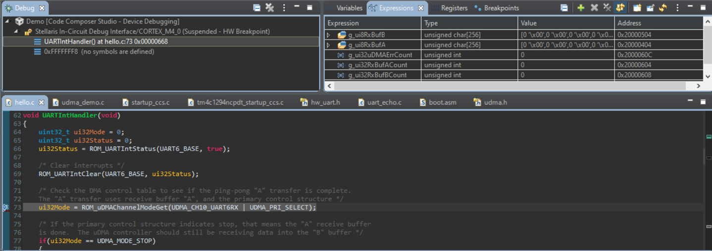
我已经修改了基本 UART_echo 示例、但很明显地更改了周围的内容、以便接收到的数据来自传感器、而不是来自用户的手动输入。 然后、当数据在 UART6上传入时、我会在 UART0上打印出来、并可以在串行控制台(RealTerm)中查看数据。
问题:
在读取 DMA 并查看 UDMA_DEMO 示例后、我认为这可能是最佳方法。 但是、我正在努力调整现有代码以使用它。 例如、我看到有大量代码通过 UART TX 发送数据、这是由 DMA 促成的。 但是、我看不到许多让 DMA 简单地从 UART RX 接收数据的示例。
请注意 、UDMA_DEMO 的功能 与 我想要的类似、但我似乎无法连接点。 例如、该示例应用的一个理想特征是它已将 DMA 设置为使用某种乒乓方法。 我阅读了 TivaWare 中的文档、并认为这肯定适用于我的应用、也就是说、当我通过 UART 收集这32个字节的数据时、我可以解析之前收集的帧(32字节)、 并在下一个32字节块出现时执行相应的操作。
我想这是一个很长的提问时间、这是我关于 DMA 如何与 UART RX 有效交互的思考过程(上面提到的外设管道思想)。 如果是、下一步的最佳方法是什么。 在 TivaWare 中是否有任何其他示例可供您考虑、在这种情况下、这些示例可能会有所帮助?
谢谢!
参考代码:
#include <stdint.h> #include <stdbool.h> #include "inc/hw_ints.h" #include "inc/hw_memmap.h" #include "driverlib/debug.h" #include "driverlib/gpio.h" #include "driverlib/interrupt.h" #include "driverlib/pin_map.h" #include "driverlib/rom.h" #include "driverlib/rom_map.h" #include "driverlib/sysctl.h" #include "driverlib/uart.h" uint32_t g_ui32SysClock; #ifdef DEBUG void __error__(char *pcFilename, uint32_t ui32Line) { } #endif void UARTIntHandler(void) { uint32_t ui32Status; ui32Status = ROM_UARTIntStatus(UART6_BASE, true); /* Clear interrupts */ ROM_UARTIntClear(UART6_BASE, ui32Status); /* Read data */ while(ROM_UARTCharsAvail(UART6_BASE)) { /* Should move to blocking charGet() */ ROM_UARTCharPutNonBlocking(UART0_BASE, ROM_UARTCharGetNonBlocking(UART6_BASE)); /* Toggle LED for testing */ GPIOPinWrite(GPIO_PORTN_BASE, GPIO_PIN_0, GPIO_PIN_0); SysCtlDelay(g_ui32SysClock / (1000 * 3)); GPIOPinWrite(GPIO_PORTN_BASE, GPIO_PIN_0, 0); } } int main(void) { /* 120Mhz */ g_ui32SysClock = MAP_SysCtlClockFreqSet((SYSCTL_XTAL_25MHZ | SYSCTL_OSC_MAIN | SYSCTL_USE_PLL | SYSCTL_CFG_VCO_480), 120000000); /* LED */ ROM_SysCtlPeripheralEnable(SYSCTL_PERIPH_GPION); ROM_GPIOPinTypeGPIOOutput(GPIO_PORTN_BASE, GPIO_PIN_0); /* UART 6 */ ROM_SysCtlPeripheralEnable(SYSCTL_PERIPH_UART6); ROM_SysCtlPeripheralEnable(SYSCTL_PERIPH_GPIOP); /* UART 0 */ ROM_SysCtlPeripheralEnable(SYSCTL_PERIPH_UART0); ROM_SysCtlPeripheralEnable(SYSCTL_PERIPH_GPIOA); ROM_IntMasterEnable(); /* Configure As UART 6 on PP0/1 */ GPIOPinConfigure(GPIO_PP0_U6RX); GPIOPinConfigure(GPIO_PP1_U6TX); ROM_GPIOPinTypeUART(GPIO_PORTP_BASE, GPIO_PIN_0 | GPIO_PIN_1); /* Configure As UART 1 on PA0/1 */ GPIOPinConfigure(GPIO_PA0_U0RX); GPIOPinConfigure(GPIO_PA1_U0TX); ROM_GPIOPinTypeUART(GPIO_PORTA_BASE, GPIO_PIN_0 | GPIO_PIN_1); /* 115200 8-N-1 */ ROM_UARTConfigSetExpClk(UART6_BASE, g_ui32SysClock, 115200, (UART_CONFIG_WLEN_8 | UART_CONFIG_STOP_ONE | UART_CONFIG_PAR_NONE)); ROM_UARTConfigSetExpClk(UART0_BASE, g_ui32SysClock, 115200, (UART_CONFIG_WLEN_8 | UART_CONFIG_STOP_ONE | UART_CONFIG_PAR_NONE)); /* Enable ISR */ ROM_IntEnable(INT_UART6); ROM_IntEnable(INT_UART0); ROM_UARTIntEnable(UART6_BASE, UART_INT_RX | UART_INT_RT); while(1){} }
在这种情况下、将 UDMA 用于 UART RX 是很有意义的。 您看不到将 UDMA 用于 UART RX 的示例、因为接收的字符数通常是未知的。 在这种情况下、UDMA 不能正常工作。 在这种情况下、连续字符流以32个块的形式进行分组、在乒乓模式下使用 UDMA 是非常有意义的。 我看到的唯一问题是同步、这样您就不会在32字符串的中间开始接收。
尊敬的 Bob:
感谢您的反馈!
在确保 UART 按预期工作后、我继续执行上述实现。 我基本上使用了 UDMA_DEMO、与 DriverLib 文档中的 DMA 部分结合使用。 具体侧重于第31.2.1节、其中列出了设置 DMA 的一般步骤。
我已经附上了代码供参考、我认为我已经接近了、但我可能错过了一个步骤。
我可以看到 UART ISR 被调用、但 DMA 缓冲区未被填满。
为了使调试器的操作更加简单、我在中将 UART/DMA 配置进行了隔离 configDmaWithUart().
乍一看、下面的函数中是否有任何看起来不合适的东西。 或者是否有任何可能导致我所看到问题的危险信号?
谢谢!
参考代码:
#include <stdint.h> #include <string.h> #include <stdbool.h> #include "inc/hw_ints.h" #include "inc/hw_memmap.h" #include "inc/hw_uart.h" #include "driverlib/debug.h" #include "driverlib/gpio.h" #include "driverlib/interrupt.h" #include "driverlib/pin_map.h" #include "driverlib/rom.h" #include "driverlib/rom_map.h" #include "driverlib/sysctl.h" #include "driverlib/uart.h" #include "driverlib/udma.h" uint32_t g_ui32SysClock; #if defined(ewarm) #pragma data_alignment=1024 uint8_t pui8ControlTable[1024]; #elif defined(ccs) #pragma DATA_ALIGN(pui8ControlTable, 1024) uint8_t pui8ControlTable[1024]; #else uint8_t pui8ControlTable[1024] __attribute__ ((aligned(1024))); #endif #ifdef DEBUG void __error__(char *pcFilename, uint32_t ui32Line) { } #endif #define UART_RXBUF_SIZE 256 static uint32_t g_ui32RxBufACount = 0; static uint32_t g_ui32RxBufBCount = 0; static uint32_t g_ui32uDMAErrCount = 0; static uint8_t g_ui8RxBufA[UART_RXBUF_SIZE]= {0}; static uint8_t g_ui8RxBufB[UART_RXBUF_SIZE] = {0}; static void configDmaWithUart(void); void uDMAErrorHandler(void) { uint32_t ui32Status; /* Check for uDMA error bit */ ui32Status = ROM_uDMAErrorStatusGet(); /* If there is a uDMA error, then clear the error and increment the error counter */ if(ui32Status) { ROM_uDMAErrorStatusClear(); g_ui32uDMAErrCount++; } } void UARTIntHandler(void) { uint32_t ui32Mode = 0; uint32_t ui32Status = 0; ui32Status = ROM_UARTIntStatus(UART6_BASE, true); /* Clear interrupts */ ROM_UARTIntClear(UART6_BASE, ui32Status); /* Check the DMA control table to see if the ping-pong "A" transfer is complete. The "A" transfer uses receive buffer "A", and the primary control structure */ ui32Mode = ROM_uDMAChannelModeGet(UDMA_CH10_UART6RX | UDMA_PRI_SELECT); /* If the primary control structure indicates stop, that means the "A" receive buffer is done. The uDMA controller should still be receiving data into the "B" buffer */ if(ui32Mode == UDMA_MODE_STOP) { /* Increment a counter to indicate data was received into buffer A */ g_ui32RxBufACount++; /* Set up the next transfer for the "A" buffer, using the primary control structure. When the ongoing receive into the "B" buffer is done, the uDMA controller will switch */ ROM_uDMAChannelTransferSet(UDMA_CH10_UART6RX | UDMA_PRI_SELECT, UDMA_MODE_PINGPONG, (void *)(UART6_BASE + UART_O_DR), g_ui8RxBufA, sizeof(g_ui8RxBufA)); } /* Check the DMA control table to see if the ping-pong "B" transfer is complete. The "B" transfer uses receive buffer "B", and the alternate control structure */ ui32Mode = ROM_uDMAChannelModeGet(UDMA_CH10_UART6RX | UDMA_ALT_SELECT); /* If the alternate control structure indicates stop, that means the "B" receive buffer is done. The uDMA controller should still be receiving data into the "A" buffer */ if(ui32Mode == UDMA_MODE_STOP) { /* Increment a counter to indicate data was received into buffer A */ g_ui32RxBufBCount++; /* Set up the next transfer for the "B" buffer, using the alternate control structure. When the ongoing receive into the "A" buffer is done, the uDMA controller will switch */ ROM_uDMAChannelTransferSet(UDMA_CH10_UART6RX | UDMA_ALT_SELECT, UDMA_MODE_PINGPONG, (void *)(UART6_BASE + UART_O_DR), g_ui8RxBufB, sizeof(g_ui8RxBufB)); } /* Toggle LED for testing */ GPIOPinWrite(GPIO_PORTN_BASE, GPIO_PIN_0, GPIO_PIN_0); SysCtlDelay(g_ui32SysClock / (1000 * 3)); GPIOPinWrite(GPIO_PORTN_BASE, GPIO_PIN_0, 0); } static void configDmaWithUart(void) { /* Enable DMA peripheral */ ROM_SysCtlPeripheralEnable(SYSCTL_PERIPH_UDMA); ROM_SysCtlPeripheralSleepEnable(SYSCTL_PERIPH_UDMA); /* Enable UART 6 peripheral */ ROM_SysCtlPeripheralEnable(SYSCTL_PERIPH_UART6); ROM_SysCtlPeripheralEnable(SYSCTL_PERIPH_GPIOP); ROM_SysCtlPeripheralSleepEnable(SYSCTL_PERIPH_UART6); /* Configure As UART 6 on PP0/1 */ GPIOPinConfigure(GPIO_PP0_U6RX); GPIOPinConfigure(GPIO_PP1_U6TX); ROM_GPIOPinTypeUART(GPIO_PORTP_BASE, GPIO_PIN_0 | GPIO_PIN_1); /* UART 6 @ 115200 8-N-1 */ ROM_UARTConfigSetExpClk(UART6_BASE, g_ui32SysClock, 115200, (UART_CONFIG_WLEN_8 | UART_CONFIG_STOP_ONE | UART_CONFIG_PAR_NONE)); /* Not sure about TX, but I know RX will have 4 byte threshold */ ROM_UARTFIFOLevelSet(UART6_BASE, UART_FIFO_TX4_8, UART_FIFO_RX4_8); /* Enable the UART for operation, and enable the uDMA interface for RX only */ ROM_UARTEnable(UART6_BASE); ROM_UARTDMAEnable(UART6_BASE, UART_DMA_RX); /* Enable DMA interrupts */ ROM_IntEnable(INT_UDMAERR); /* Enable DMA */ ROM_uDMAEnable(); /* Point at the control table to use for channel control structures */ ROM_uDMAControlBaseSet(pui8ControlTable); /* Put the attributes in a known state */ ROM_uDMAChannelAttributeDisable(UDMA_CH10_UART6RX, UDMA_ATTR_ALTSELECT | UDMA_ATTR_USEBURST | UDMA_ATTR_HIGH_PRIORITY | UDMA_ATTR_REQMASK); /* Enable DMA attributes for UART6 RX (buffer A). In this case, the transfer data size is 8 bits, the source address does not increment since it will be reading from a register. The destination address increment is byte 8-bit bytes. The arbitration size is set to 4 to match the RX FIFO trigger threshold */ ROM_uDMAChannelControlSet(UDMA_CH10_UART6RX | UDMA_PRI_SELECT, UDMA_SIZE_8 | UDMA_SRC_INC_NONE | UDMA_DST_INC_8 | UDMA_ARB_4); /* Enable DMA attributes for UART6 RX (buffer B). Setting this an the alternate control structure B. Configuration is the same as above */ ROM_uDMAChannelControlSet(UDMA_CH10_UART6RX | UDMA_ALT_SELECT, UDMA_SIZE_8 | UDMA_SRC_INC_NONE | UDMA_DST_INC_8 | UDMA_ARB_4); /* Set transfer parameters for the primary RX control structure in ping-pong mode. The transfer source will be the UART RX data register, and the destination will be buffer A */ ROM_uDMAChannelTransferSet(UDMA_CH10_UART6RX | UDMA_PRI_SELECT, UDMA_MODE_PINGPONG, (void *)(UART6_BASE + UART_O_DR), g_ui8RxBufA, sizeof(g_ui8RxBufA)); /* Same logic applies above, except we are now setting up the alternative buffer (B) */ ROM_uDMAChannelTransferSet(UDMA_CH10_UART6RX | UDMA_ALT_SELECT, UDMA_MODE_PINGPONG, (void *)(UART6_BASE + UART_O_DR), g_ui8RxBufB, sizeof(g_ui8RxBufB)); /* The DMA should now be configured for UART RX in ping-ping mode, with both primary and secondary buffers pointing to the UART data register */ ROM_uDMAChannelEnable(UDMA_CH10_UART6RX); /* Enable DMA for UART RX. Stop DMA if there's a UART error */ ROM_UARTDMAEnable(UART6_BASE, UART_DMA_RX | UART_DMA_ERR_RXSTOP); /* Enable UART */ ROM_IntEnable(INT_UART6); ROM_UARTIntEnable(UART6_BASE, UART_INT_RX | UART_INT_RT); } int main(void) { /* 120Mhz */ g_ui32SysClock = MAP_SysCtlClockFreqSet((SYSCTL_XTAL_25MHZ | SYSCTL_OSC_MAIN | SYSCTL_USE_PLL | SYSCTL_CFG_VCO_480), 120000000); /* LED */ ROM_SysCtlPeripheralEnable(SYSCTL_PERIPH_GPION); ROM_SysCtlPeripheralEnable(SYSCTL_PERIPH_GPIOA); ROM_GPIOPinTypeGPIOOutput(GPIO_PORTN_BASE, GPIO_PIN_0); /* Enable UART 0 peripheral */ ROM_SysCtlPeripheralEnable(SYSCTL_PERIPH_UART0); ROM_SysCtlPeripheralSleepEnable(SYSCTL_PERIPH_UART0); /* Enable processor interrupts */ ROM_IntMasterEnable(); /* Configure As UART 1 on PA0/1 */ GPIOPinConfigure(GPIO_PA0_U0RX); GPIOPinConfigure(GPIO_PA1_U0TX); ROM_GPIOPinTypeUART(GPIO_PORTA_BASE, GPIO_PIN_0 | GPIO_PIN_1); /* 115200 8-N-1 */ ROM_UARTConfigSetExpClk(UART0_BASE, g_ui32SysClock, 115200, (UART_CONFIG_WLEN_8 | UART_CONFIG_STOP_ONE | UART_CONFIG_PAR_NONE)); /* Enable ISR */ ROM_IntEnable(INT_UART0); configDmaWithUart(); memset(g_ui8RxBufA, 0x00, sizeof(g_ui8RxBufA)); memset(g_ui8RxBufB, 0x00, sizeof(g_ui8RxBufB)); /* Spin */ while(1) { SysCtlDelay(g_ui32SysClock / 20 / 3); } }
我将在星期一回到办公室时详细了解代码。 我附加了一个在乒乓模式下使用 UDMA 的 ADC 示例。 它可能会有所帮助。
感谢 Bob Crosby、您的示例无疑对您有所帮助。
我在这个周末做了一些工作、让它稍微工作。 我还借鉴了您所附的 ADC 示例中的一些想法、以帮助进行调试。
到目前为止我发现、如果我使用 UART RX 0或1、它就可以工作、从我可以看到 DMA 缓冲区已满的意义上讲。 我需要验证数据、但它在某种程度上是有效的。
我正在努力解决的另一个主题是 UART 与 DMA 的关系、特别是在中断方面。 我在浏览 TI 的文档时查看了是否有任何有关 DMA 的应用手册、但找不到任何应用手册。 基本上、在我的代码中、我正在注册几个不同的中断、但我是盲目地这样做的、因为我不一定知道需要哪些中断。 例如:
/* The DMA should now be configured for UART RX in ping-ping mode, with both primary and secondary buffers pointing to the UART data register */ ROM_uDMAChannelEnable(UDMA_CHANNEL_UART1RX); /* Enable DMA for UART RX. Stop DMA if there's a UART error */ ROM_UARTDMAEnable(UART1_BASE, UART_DMA_RX | UART_DMA_ERR_RXSTOP); /* Enable UART */ ROM_IntEnable(INT_UART1); ROM_UARTIntEnable(UART1_BASE, UART_INT_RX | UART_INT_RT); ROM_UARTIntEnable(UART1_BASE, UART_INT_DMATX | UART_INT_DMARX);
"首先接收 UART RX 中断、然后让 DMA 执行 X、因此如果您希望 DMA 缓冲区填充(n)个字节、则需要注册 X ISR。"
udma.h
,它们有31个默认信道号,例如UDMA_CHANNEL_XXXX
。 我用于 UART 6 RX 的 UART 没有映射到其中的任何一个。 因此我切换到了一个映射的(UDMA_CHANNEL_UART1RX
),然后一切开始工作。 UDMA_CH10_UART6RX
,但这可能不是 API 的使用方式,或者它们是通用定义,我的特定 LaunchPad 不支持该 DMA 通道? 总之、只是想知道您的想法。 再次感谢您的帮助!
要将 UART6与 UDMA 配合使用,您需要使用所有附加函数 uDMAChannelAssign()。 32个 uDMA 通道最多可以有9个不同的连接。 为了实现兼容性,如果通道映射到组0 (例如通道8上的 UART1RX),则不需要调用 uDMAChannelAssign()函数。
uDMAChannelAssign(UDMA_CH10_UART6RX); uDMAChannelAssign(UDMA_CH11_UART6TX); uDMAChannelEnable(UDMA_CH10_UART6RX); uDMAChannelEnable(UDMA_CH11_UART6TX);
在本例中、我认为这不会产生太大的影响。 如果您使用 FIFO、UART 将发出突发 UDMA 请求。 其它 DMA 请求将被忽略、直到突发完成。 (CPU 仍将获得所需的任何总线周期、如果需要、中断突发。) 从 DMA 的角度来看、猝发请求的效率略高。 它确实会增加其他 DMA 请求的延迟、但如果仅将 UART 用于 DMA、则使用 FIFO 会带来更多延迟。 如果您仅使用一个 UDMA 通道、则差异完全无关紧要。 这是数据表中的一些信息。