请注意,本文内容源自机器翻译,可能存在语法或其它翻译错误,仅供参考。如需获取准确内容,请参阅链接中的英语原文或自行翻译。
器件型号:EK-TM4C123GXL 主题中讨论的其他器件: DK-TM4C123G
我最近购买 了 BOOSTXL-SENSHUB、并有兴趣将其 MPU-9150与 EK-TM4C123GXL 搭配使用。 CCS 中使用 MPU-9150的示例可以按预期工作、但它是非 RTOS 示例。 我计划将 MPU-9150用于 TI-RTOS 应用。
在 zip 文件中找到了与我所需内容最接近的示例、链接如下: http://processors.wiki.ti.com/index.php/TI-RTOS_MPU9150
我注意到、该示例中存在一些差异、例如、TI-RTOS GPIO 驱动程序用于将引脚 PB2配置为输入以及在下降沿发出中断。 我知道、为了使用 MPU9150.h 中的便捷 MPU9150 API、必须进行一些更改
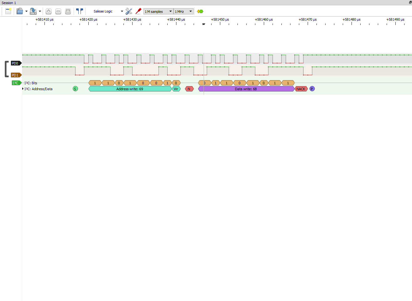
我当前的问题是在主程序 上,MPU9150_init()返回 false。 我不确定原因、但我想我需要对 MPU9150.c 进行一些更改、例如添加了一个传输模式、DK-TM4C123G TI-RTOS 示例中的 MPU9150.c 似乎没有这种模式。 我已经进一步研究了这个问题、在 MPU9150.c 中、由于 I2C_TRANSF()返回 false、将返回 null。 我将在下面发布我的部分代码以及我的项目。
e2e.ti.com/.../TI_5F00_RTOS_5F00_MPU9150.zip
MPU9150_handle MPU9150_init (unsigned int mpu9105Index、
unsigned int i2cIndex、
uint8_t i2cAddr)
{
I2C_Params i2cParams;
I2C_Transaction i2cTransaction;
ERROR_Block EB;
booltransferOK;
uint8_twriteBuffer[5];
uint8_treadBuffer[1];
MPU9150_Handlehandle =&object[mpu9105Index];

/*检查句柄是否已打开*/
if (((mpu9105Index > MPU9150_count)||(handle->i2c!= NULL)){


返回(NULL);
}

/*
*创建 GateMutex 以保证从 MPU9150接收到的数据
*保留其一致性。
*
ERROR_INIT (&EB);
Handle->DataAccess = GateMutex_create (NULL、&EB);

if (!handle->DataAccess){


返回(NULL);
}


/*创建 I2C 以供使用*/
I2C_Params_init (&i2cParams);
i2cParams.bitrate = I2C_400kHz;
handle->i2c = I2C_open (i2cIndex、&i2cParams);
handle->i2cAddr = i2cAddr;

/*如果 I2C 控制器正确打开,请继续*/
if (handle ->i2c){

/*由所有 I2C 传输使用*/
i2cTransaction.slaveAddress = i2cAddr;
i2cTransaction.writeBuf = writeBuffer;
i2cTransaction.readBuf = readBuffer;


/*将 MPU9150置于复位状态*/
writeBuffer[0]= MPU9150_O_PWR_Mgmt_1;
writeBuffer[1]= MPU9150_PWR_Mgmt_1_DEVICE_RESET;
i2cTransaction.writeCount = 2;
i2cTransaction.ReadCount = 0;

//此 if 语句中找到问题
if (!I2C_transfer (handle->i2c、&i2cTransaction)){

//添加
system_printf ("I2C_transfer ()返回 false \n 正在关闭程序\n");
system_flush();

return (NULL);
}

/*
检查从状态读回的值以确定设备
*是否仍处于复位状态或是否就绪。 该
*寄存器的复位状态为0x40、其中 SLEEP 位已置位。 器件还
可以*在
其内部复位的早期阶段使用地址 NACK 进行响应。 继续轮询、直到我们确认器件
已*就绪。
*
writeBuffer[0]= MPU9150_O_PWR_Mgmt_1;
i2cTransaction.writeCount = 1;
i2cTransaction.ReadCount = 1;
执行{
transferOK = I2C_transfer (handle->i2c、&i2cTransaction);
} while ((readBuffer[0]!= MPU9150_PWR_Mgmt_1_SLEEP)||(!transferOK));

/*使器件退出复位状态并启用时钟*/
writeBuffer[0]= MPU9150_O_PWR_Mgmt_1;
writeBuffer[1]= MPU9150_PWR_Mgmt_1_CLKSEL_XG;
i2cTransaction.writeCount = 2;
i2cTransaction.ReadCount = 0;
if (!I2C_transfer (handle->i2c、&i2cTransaction)){
return (NULL);
}

/*在 MPU9150上启用 I2C 主模式*/
writeBuffer[0]= MPU9150_O_USER_CTRL;
writeBuffer[1]= MPU9150_USER_CTRL_I2C_MST_EN;
i2cTransaction.writeCount = 2;
i2cTransaction.ReadCount = 0;
if (!I2C_transfer (handle->i2c、&i2cTransaction)){


//添加


返回值(NULL);
}

/*
*更改为功率模式完成、器件已准备好进行配置。
*设置 MPU97.的采样率
*将采样率设置为50赫兹。 1000Hz /(1 + 19)
*
writeBuffer[0]= MPU9150_O_SMPLRT_DIV;
writeBuffer[1]= 19;
i2cTransaction.writeCount = 2;
i2cTransaction.ReadCount = 0;
if (!I2C_transfer (handle->i2c、&i2cTransaction)){


return (NULL);
}

/*
编写 I2C 主设备延迟控制、以便我们每
隔5次采样 accel/Gyro 就只对 AK *采样一次。 延迟计数本身
*在下一状态处理。
*
writeBuffer[0]= MPU9150_O_I2C_MST_DELAY_CTRL;
writeBuffer[1]=(MPU9150_I2C_MST_DELAY_CTRL_I2C_SLV0_DLY_EN |
MPU9150_I2C_MST_DELAY_CTRL_I2C_SLV4_DLY_EN);
i2cTransaction.writeCount = 2;
i2cTransaction.ReadCount = 0;
if (!I2C_transfer (handle->i2c、&i2cTransaction)){


return (NULL);
}

/*
*写入 I2C 主控制时钟400kHz 的配置
*并等待外部传感器、然后再将数据置为就绪
*/
writeBuffer[0]= MPU9150_O_I2C_MST_CTRL;
writeBuffer[1]=(MPU9150_I2C_MST_CTRL_I2C_MST_CLK_400 |
MPU9150_I2C_MST_CTRL_WAIT_for_ES);

//
*配置 I2C 从器件0以读取 AK8975 (I2C 地址0x0C)
*从 AK8975寄存器状态1 (0x02)开始
*/
writeBuffer[2]= MPU9150_I2C_SLV0_ADDR_RW | 0x0C;
writeBuffer
= 0x150_2C_01 = 0x02_R2C_01;写入缓冲器0x150_0x0002C_0002C_0002C_0002C_0002C_0002C_0002C_0002C_0002C_0001_0008_0001_0001_
i2cTransaction.writeCount = 5;
i2cTransaction.ReadCount = 0;
if (!I2C_transfer (handle->i2c、&i2cTransaction)){


return (NULL);
}

/*
*将 I2C 从机4事务的配置写入 AK8975
* 0x0c 是 i2c 总线上的 AK8975地址。
*我们要向控制寄存器写入
*开始单次测量的值。
*
writeBuffer[0]= MPU9150_O_I2C_SLV4_ADDR;
writeBuffer[1]= 0x0C;
writeBuffer[2]= 0x0A;//AK8975_O_CNTL
writeBuffer[3]= 0x01;//AK8975_CNTL_MODE_SINGeBuffer[4]
= MPU9150_SIC_04;/AK9150_SIC_CTRL
i2cTransaction.writeCount = 5;
i2cTransaction.ReadCount = 0;
if (!I2C_transfer (handle->i2c、&i2cTransaction)){


return (NULL);
}

/*
*编写特定于应用的传感器配置、如滤波器
*设置和传感器范围设置。
*
writeBuffer[0]= MPU9150_O_CONFIG;
writeBuffer[1]= MPU9150_CONFIG_DLPF_CFG_94_98;
writeBuffer[2]= MPU9150_gyro_CONFIG_FS_SEL_250;
writeBuffer[3]=(MPU9150_ACCEL_CONFIG_ACCEL_HPF_5Hz |
MPU9150_ACCEL_CONFIG_AFS_SEL_2G);
i2cTransaction.writeCount = 4;
i2cTransaction.ReadCount = 0;
if (!I2C_transfer (handle->i2c、&i2cTransaction)){
return (NULL);
}

/*
配置 MPU9150的数据就绪中断引脚输出。
*
writeBuffer[0]= MPU9150_O_INT_PIN_CFG;
writeBuffer[1]= MPU9150_INT_PIN_CFG_INT_LEVEL |
MPU9150_INT_PIN_CFG_INT_RD_CLEAR |
MPU9150_INT_PIN_CFG_LATCH_INT_EN;
writeBuffer[2]= MPU9150_INT_ENABLE_DATA_RDY_EN;
i2cTransaction.writeCount = 3;
i2cTransaction.ReadCount = 0;
if (!I2C_transfer (handle->i2c、&i2cTransaction)){


return (NULL);
}

返回(句柄);
}
否则{


返回(NULL);
}
}