This thread has been locked.

If you have a related question, please click the "Ask a related question" button in the top right corner. The newly created question will be automatically linked to this question.

[参考译文] CCS/TM4C129ENCPDT:使用 tm4c129e 获取 MPU6050数据时出现问题

Guru**** 2446730 points


请注意,本文内容源自机器翻译,可能存在语法或其它翻译错误,仅供参考。如需获取准确内容,请参阅链接中的英语原文或自行翻译。

https://e2e.ti.com/support/microcontrollers/arm-based-microcontrollers-group/arm-based-microcontrollers/f/arm-based-microcontrollers-forum/633232/ccs-tm4c129encpdt-problem-acquiring-mpu6050-data-using-the-tm4c129e

器件型号:TM4C129ENCPDT

工具/软件:Code Composer Studio

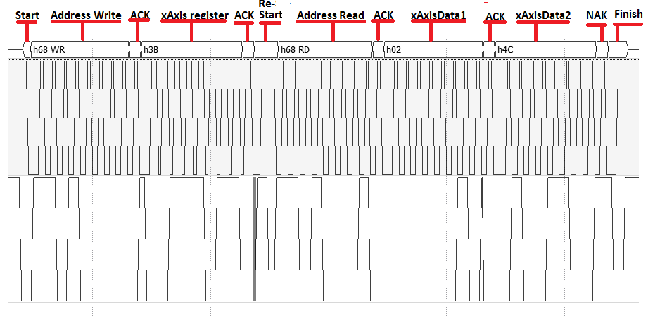
大家好、我一直在使用 MPU6050、按照 Arduino 配置、我能够设置0x6B 寄存  器、MPU6050似乎正在向我发送 ACK、但从寄存器为0x3B 和0x3C 的 x 轴加速器获取数据时遇到问题。 输出(pui32DataRx)始终为0、我不知道错误的位置。 这里是代码、有人配置了 TM4C129、以便使用 I2C 与 MPU6050配合使用??

#include 
#include 
#include "inc/hw_i2c.h"
#include "inc/hw_memmap.h"
#include "inc/hw_types.h"
#include "driverlib/gpio.h"
#include "driverlib/i2c.h"
#include "driverlib/pin_map.h"
#include "driverlib/sysctio.uarth"
#include "UART"


//
//要发送的 I2C 数据包数量。
////
*****************
#define NUM_I2C_DATA 3
#define SLAVE_ADDRESS 0x68

uint32_t ui32SysClock;
uint32_t pui32DataTx[NUM_I2C_DATA];
uint32_t pui32DataRx[2];
uint32_t ejeX;
int end = 0;

//*********
//
//配置 I2C0主机和从机,并使用环回模式连接它们。
////
*****************
int
main (void)
{

uint32_t ui32Index;

ui32SysClock = SysCtlClockFreqSet ((SYSCTL_XTAL_25MHz |
SYSCTL_OSC_MAIN |
SYSCTL_USE_PLL |
SYSCTL_CFG_VCO_480)、120000000);

//使用前必须启用 I2C0外设。

SysCtlPeripheralEnable (SYSCTL_Periph_I2C0);
SysCtlPeripheralEnable (SYSCTL_Periph_GPIOB);

GPIOPinConfigure (GPIO_PB2_I2C0SCL);
GPIOPinConfigure (GPIO_PB3_I2C0SDA);

GPIOPinTypeI2CSCL (GPIO_PORTB_BASE、GPIO_PIN_2);
GPIOPinTypeI2C (GPIO_PORTB_BASE、GPIO_PIN_3);

// I2CLoopbackEnable (I2C0_BASE);
I2CMasterInitExpClk (I2C0_BASE、ui32SysClock、false);
I2CSlaveEnable (I2C0_BASE); //洛普伊多高贵
I2CSlaveInit (I2C0_BASE、SLAVE_ADDRESS); //Setea la dirección ó n del esclavo
I2CMasterSlaveAddrSet (I2C0_BASE、SLAVE_ADDRESS、FALSE); //假的 escribir al esclavo,真的 para leer al esclavo

//初始化要发送的数据。
pui32DataTx[0]= 0x6B;
pui32DataTx[1]= 0x00;

for (ui32Index = 0;ui32Index < 2;ui32Index++)
{

I2CMasterDataPut (I2C0_BASE、pui32DataTx[ui32Index]); //将要发送的数据放在数据寄存器中
I2CMasterControl (I2C0_BASE、I2C_MASTER_CMD_SINGLE_SEND);

while (!(I2CSlaveStatus (I2C0_BASE)& I2C_SLAVE_ACT_RREQ)// espera ACK del esclavo del recoissimiento de datos
{
}

pui32DataRx[ui32Index]= I2CSlaveDataGet (I2C0_BASE);// Lee la data del esclavo

while (I2CMasterBusy (I2C0_BASE))//espera que el modulo maestro termine con la transferencia
{
}

end++;
}

I2CMasterSlaveAddrSet (I2C0_BASE、SLAVE_ADDRESS、TRUE); //假的 escribir al esclavo,真的 para leer al esclavo

while (1)
{
I2CMasterDataPut (I2C0_BASE、0x3B); //将要发送的数据放在数据寄存器中
I2CMasterControl (I2C0_BASE、I2C_MASTER_CMD_SINGLE_Receive);

while (!(I2CSlaveStatus (I2C0_BASE)& I2C_SLAVE_ACT_TREQ)// espera ACK del esclavo del recoissimiento de datos
{
}

pui32DataRx[0]= I2CMasterDataGet (I2C0_BASE)<<8;

I2CMasterDataPut (I2C0_BASE、0x3C); //将要发送的数据放在数据寄存器中
I2CMasterControl (I2C0_BASE、I2C_MASTER_CMD_SINGLE_Receive);

while (!(I2CSlaveStatus (I2C0_BASE)& I2C_SLAVE_ACT_TREQ)// espera ACK del esclavo del recoissimiento de datos
{
}

pui32DataRx[1]= I2CMasterDataGet (I2C0_BASE);
ejeX = pui32DataRx[0]|pui32DataRx[1];
}

// return (0);
}

  • 请注意,本文内容源自机器翻译,可能存在语法或其它翻译错误,仅供参考。如需获取准确内容,请参阅链接中的英语原文或自行翻译。

    [引用用户="Sergio Mamani"]输出... 从 x 轴加速计 (Pui32DataRx)... 始终为0[/报价]

    进行此类测量时、您不会说"器件的状况"。   通过将该轴与重力的拉力对齐、您的读数是否可能会"从零漂移?"

    我没有查看过您的代码-因此、"快速/脏"测试(我的测试类型)似乎是一种"轻松且有利的方法" 、它不是吗?

    通常情况下、"此处的帮助者询问2条 I2C 信号线路上是否存在(有效)上拉电阻器"。   然而-您声称(部分)注册和 ACK 成功-因此(部分)电阻器(必须)存在...

    [编辑]现在已经过去了几个小时(自编写上述内容以来)、(我的工作日现在已经过去了)我注意到:

    " while(I2CMasterBusy(I2C0_BASE))"    Has not this code been replaced - when employing the "129 family?"   I recall a "back to back" read of MCU status - which (proves able)to detect the change of state of the "129's" busy.    I don't use the 129 family - do check this - just in case.    In addition - year or more back - gifted vendor agent Amit Ashara produced a most valuable - I2C based APP Note - which resides (somewhere!)    (to my mind - vendor delights in making the discovery and/or location of such critical documents - difficult!)    I've endlessly protested - vendor responded by "banning LIKE."

  • 请注意,本文内容源自机器翻译,可能存在语法或其它翻译错误,仅供参考。如需获取准确内容,请参阅链接中的英语原文或自行翻译。

    好的、使用我能够在 TM4C 中复制的逻辑解串器、Arduino 用于配置 MPU6050的配置序列(仅设置为0x00 PWR_Mgmt_1寄存器)、MPU6050发送了 ACK、一切都正常、 从这里、我认为其余的都很简单、因为我知道 如何使用 I2C 进行突发发送、但问题 在于读取数据。

    因此、使用逻辑分析仪、我能够看到通过 I2C 总线的数据序列是什么、下图(使用 Arduino):

    首先、主器件必须在 I2C 总线中从 xAxis (0x3B)写入寄存器、然后将主器件配置为读取(重新启动)、然后从 xAxis 寄存器中读取16字节数据。 为了在 I2C 总线上写入(0x3B)、我已经生成了下一个代码、然后将主器件配置为读取、但出于某种原因、在第二个 while 循环中、代码停留在标记的行中:

    while (1)
    {
    I2CMasterSlaveAddrSet (I2C0_BASE、SLAVE_ADDRESS、FALSE); //向 MPU6050写入错误
    
    I2CMasterDataPut( I2C0_BASE,0x3B ); //发送寄存器0x3B
    I2CMasterControl (I2C0_BASE、I2C_MASTER_CMD_SINGLE_SEND);
    while (I2CMasterBusy (I2C0_BASE)){} //此处代码卡在第二个 while 循环中<--------
    while (!(I2CSlaveStatus (I2C0_BASE)& I2C_SLAVE_ACT_RREQ){}
    pui32DataRx[0]= I2CSlaveDataGet (I2C0_BASE);
    
    I2CMasterSlaveAddrSet (I2C0_BASE、SLAVE_ADDRESS、TRUE); //True 可从 MPU6050读取
    
    I2CMasterControl (I2C0_BASE、I2C_MASTER_CMD_BURST_Receive_start);//启动"猝发读取"并读取0x3B 寄存器
    while (!(I2CSlaveStatus (I2C0_BASE)& I2C_SLAVE_ACT_TREQ)){};
    DATA[0]= I2CMasterDataGet (I2C0_BASE);
    
    I2CMasterControl (I2C0_BASE、I2C_MASTER_CMD_BURST_Receive_CONT);//读取下一个寄存器0x3C
    while (!(I2CSlaveStatus (I2C0_BASE)& I2C_SLAVE_ACT_TREQ)){};
    DATA[1]=I2CMasterDataGet (I2C0_BASE);
    
    I2CMasterControl (I2C0_BASE、I2C_MASTER_CMD_BURST_Receive_finish);//完成"猝发读取"
    while (!(I2CSlaveStatus (I2C0_BASE)& I2C_SLAVE_ACT_TREQ)){};
    } 

    下面是完整的代码:

    #include 
    #include 
    #include "inc/hw_i2c.h"
    #include "inc/hw_memmap.h"
    #include "inc/hw_types.h"
    #include "driverlib/gpio.h"
    #include "driverlib/i2c.h"
    #include "driverlib/pin_map.h"
    #include "driverlib/ssysctidio.32_uint32_uattru32_u32_u_uintu32_u_u32u_uintu_u32u_uintu_uintu32u_u_uintu32u_uintu32u_uintu_uintuintu_u32u_uintuintu_uintuintu_uintuintu32_uintuintuintu_uintu_uintuintuintuintu_uintuintuintuintuintu_uintuintuintuint


    int end = 0;
    
    int main (void)
    
    {
    
    ui32SysClock = SysCtlClockFreqSet ((SYSCTL_XTAL_25MHz |
    SYSCTL_OSC_MAIN |
    SYSCTL_USE_PLL |
    SYSCTL_CFG_VCO_480)、120000000);
    
    SysCtlPeripheralEnable (SYSCTL_Periph_I2C0);
    SysCtlPeripheralEnable (SYSCTL_Periph_GPIOB);
    
    GPIOPinConfigure (GPIO_PB2_I2C0SCL);
    GPIOPinConfigure (GPIO_PB3_I2C0SDA);
    
    GPIOPinTypeI2CSCL (GPIO_PORTB_BASE、GPIO_PIN_2);
    GPIOPinTypeI2C (GPIO_PORTB_BASE、GPIO_PIN_3);
    
    I2CMasterInitExpClk (I2C0_BASE、ui32SysClock、false);
    // I2CSlaveEnable (I2C0_BASE);
    I2CSlaveInit (I2C0_BASE、SLAVE_ADDRESS); //设置从器件地址
    I2CMasterSlaveAddrSet (I2C0_BASE、SLAVE_ADDRESS、FALSE); //写入错误
    
    pui32DataTx[0]= 0x6B; //MPU6050 PWR_Mgmt_1寄存器
    pui32DataTx[1]= 0x00; //将寄存器 PWR_Mgmt_1设置为0x00
    
    I2CMasterDataPut( I2C0_BASE,pui32DataTx[0]); //启动突发发送第一个0x6B
    I2CMasterControl (I2C0_BASE、I2C_MASTER_CMD_BURST_SEND_START);
    while (I2CMasterBusy (I2C0_BASE)){}
    while (!(I2CSlaveStatus (I2C0_BASE)& I2C_SLAVE_ACT_RREQ){}
    pui32DataRx[0]= I2CSlaveDataGet (I2C0_BASE);
    
    I2CMasterDataPut( I2C0_BASE,pui32DataTx[1]); //然后发送 PWR_Mgmt_1寄存器的新值
    I2CMasterControl (I2C0_BASE、I2C_MASTER_CMD_BURST_SEND_CONT);
    while (I2CMasterBusy (I2C0_BASE)){}
    while (!(I2CSlaveStatus (I2C0_BASE)& I2C_SLAVE_ACT_RREQ){}
    pui32DataRx[1]=I2CSlaveDataGet (I2C0_BASE);
    
    I2CMasterControl (I2C0_BASE、I2C_MASTER_CMD_BURST_SEND_FINISH);//完成突发发送
    while (I2CMasterBusy (I2C0_BASE)){}
    pui32DataRx[2]=I2CSlaveDataGet (I2C0_BASE);
    
    while (1)
    {
    I2CMasterSlaveAddrSet (I2C0_BASE、SLAVE_ADDRESS、FALSE); //向 MPU6050写入错误
    
    I2CMasterDataPut( I2C0_BASE,0x3B ); //发送寄存器0x3B
    I2CMasterControl (I2C0_BASE、I2C_MASTER_CMD_SINGLE_SEND);
    while (I2CMasterBusy (I2C0_BASE)){} //此处代码卡在第二遍中<--------
    while (!(I2CSlaveStatus (I2C0_BASE)& I2C_SLAVE_ACT_RREQ){}
    pui32DataRx[0]= I2CSlaveDataGet (I2C0_BASE);
    
    I2CMasterSlaveAddrSet (I2C0_BASE、SLAVE_ADDRESS、TRUE); //True 可从 MPU6050读取
    
    I2CMasterControl (I2C0_BASE、I2C_MASTER_CMD_BURST_Receive_start);//启动"猝发读取"并读取0x3B 寄存器
    while (!(I2CSlaveStatus (I2C0_BASE)& I2C_SLAVE_ACT_TREQ)){};
    DATA[0]= I2CMasterDataGet (I2C0_BASE);
    
    I2CMasterControl (I2C0_BASE、I2C_MASTER_CMD_BURST_Receive_CONT);//读取下一个寄存器0x3C
    while (!(I2CSlaveStatus (I2C0_BASE)& I2C_SLAVE_ACT_TREQ)){};
    DATA[1]=I2CMasterDataGet (I2C0_BASE);
    
    I2CMasterControl (I2C0_BASE、I2C_MASTER_CMD_BURST_Receive_finish);//完成"猝发读取"
    while (!(I2CSlaveStatus (I2C0_BASE)& I2C_SLAVE_ACT_TREQ)){};
    }
    
    } 

    提前感谢

  • 请注意,本文内容源自机器翻译,可能存在语法或其它翻译错误,仅供参考。如需获取准确内容,请参阅链接中的英语原文或自行翻译。

    这里是从 MPU6050的 x 轴获取数据的代码、我共享它是因为我在这个论坛上没有看到任何针对一个看起来很受欢迎的问题的完整解决方案、也许对于某些人来说、这是一个很容易解决的问题 (对我来说很困难、因为这是我的第一个 I2C 程序)但我在这个论坛上几乎没有发现关于这个主题的任何内容、这真的让我很沮丧、这里还有一个 I2C 程序的链接、这对我很有帮助。

    https://github.com/lamarts/Tiva-TM4C-ARM-Coretex-M4---I2C-Sensor/blob/master/MCP9808_main.c

    代码:

    #include 
    #include 
    #include 
    #include "inc/hw_ints.h"
    #include "inc/hw_memmap.h"
    #include "inc/hw_types.h"
    #include "inc/hw_gpio.h"
    #include "inc/hw_i2c.h"
    #include "driverlib/debug.h"
    #include "driverlib/driverlib"#driverlib.driver.h"


    #define "driverlib_driverlib"#driverlib/driverlib.driverlib.driver.h"#include "driverlib#driverlib.driver.h"#include "driverlib"#driverlib.driverlib.driverlib"#define "driverlib.driverlib.driver.h"#include "driverlib"#define #driverlib"#driverlib"#driverlib.ide"#drivers.driverlib


    0x68
    #define Ambient 温度 0x3B
    #define DEVICE_ID_REGISTER 0x3B
    #define MANUFACK_ID_REGISTER 0x07
    
    uint32_t ui32SysClock;
    uint32_t ui32SysClock_2;
    int a = 0;
    uint32_t pui32DataTx[3];
    uint32_t pui32DataRx[3];
    uint16_t X;
    
    void I2C_Init ()
    {
    SysCtlPeripheralEnable (SYSCTL_Periph_I2C0);
    SysCtlPeripheralReset (SYSCTL_Periph_I2C0);
    
    SysCtlPeripheralEnable (SYSCTL_Periph_GPIOB);
    
    GPIOPinConfigure (GPIO_PB2_I2C0SCL);
    GPIOPinConfigure (GPIO_PB3_I2C0SDA);
    
    GPIOPinTypeI2CSCL (GPIO_PORTB_BASE、GPIO_PIN_2);
    GPIOPinTypeI2C (GPIO_PORTB_BASE、GPIO_PIN_3);
    
    I2CMasterInitExpClk (I2C0_BASE、4800000、false);
    }
    
    void xAxis_R (uint8_t Ambient temp_reg)
    {
    I2CMasterDataPut (I2C0_BASE、Ambient temp_reg);
    I2CMasterAxis Up_r (I2CMmaster_CMD_CMD_BASE


    = I2CM0);I2CD_0 = I2CD_UCD_16;Iint_UCD_0 = I2CD_UCD_UCD_0;I2CD_UCD_0 = I2CD_UCD_UCD_0;I2CD_0 = I2CD_UCD_UCD_0 = I2CD_UCD_0;I2CD_0 = I2CD_UCD_UCD_0;I2CD_0 = I2CD_UCD_UCD_0;I2CD_UCD_0 = I2CD_UCD_UCD_0 = I2CD_UCD_0;I2CD_UCD_0
    
    I2CMasterControl (I2C0_BASE、 I2C_MASTER_CMD_BURST_Receive_finish);
    while (I2CMasterBusy (I2C0_BASE));
    LowerByte = I2CMasterDataGet (I2C0_BASE);
    
    UPM = UpperByte<<8;
    xAxis = UPM | LowerCtl;SysDelay
    (600);
    return xAxis;
    
    }
    
    main Byte (void)
    
    ui32SysClock = SysCtlClockFreqSet ((SYSCTL_XTAL_25MHz |
    SYSCTL_OSC_MAIN |
    SYSCTL_USE_PLL |
    SYSCTL_CFG_VCO_480)、120000000);
    
    
    ui32SysClock_2 = SysCtlClockGet ();
    
    I2C_Init();
    
    SysCtlDelay (500);
    
    pui32DataTx[0]= 0x6B; //MPU6050 PWR_Mgmt_1寄存器
    pui32DataTx[1]= 0x00; //将寄存器 PWR_Mgmt_1设置为0x00
    I2CMasterSlaveAddrSet (I2C0_BASE、SLAVE_ADDRESS、FALSE);
    I2CMasterDataPut (I2C0_BASE、pui32DataTx[0]);
    I2CMasterControl (I2C0_BASE、I2C_MASTER_CMD_BURST_SEND_START);
    while (I2CMasterBusy (I2C0_BASE)){}
    
    I2CMasterDataPut (I2C0_BASE、pui32DataTx[1]);
    I2CMasterControl (I2C0_BASE、I2C_MASTER_CMD_BURST_SEND_CONT);
    while (I2CMasterBusy (I2C0_BASE)){}
    
    I2CMasterControl (I2C0_BASE、I2C_MASTER_CMD_BURST_SEND_FINISH);//完成突发发送
    while (I2CMasterBusy (I2C0_BASE)){}
    pui32DataRx[2]=I2CSlaveDataGet (I2C0_BASE);
    
    SysCtlDelay (500);
    
    while (1)
    {
    I2CMasterSlaveAddrSet (I2C0_BASE、SLAVE_ADDRESS、FALSE);
    xAxis_R (0x3B);
    while (I2CMasterBusy (I2C0_BASE)){}
    
    x = xAxis();
    
    }
    }
    

    这不是一个完整的解决方案、Y 轴和 Z 轴以及陀螺仪和温度传感器都不在该代码中、一旦我完成该代码、我将通过这篇文章进行分享。

  • 请注意,本文内容源自机器翻译,可能存在语法或其它翻译错误,仅供参考。如需获取准确内容,请参阅链接中的英语原文或自行翻译。
    在您的初始帖子中、您注意到您的"X 轴"数据(始终)为零。 有人建议您将该轴与引力场"对齐"-该引力场应提供"从零中退出"。

    今天、您提出了一个" X 轴解决方案"、但现在从不评论 X 轴数据。 这不是(完全)一致的-是吗?

    您是否有更好的方法来"生成加速"、以便实现所有轴性能-可能一天-?
  • 请注意,本文内容源自机器翻译,可能存在语法或其它翻译错误,仅供参考。如需获取准确内容,请参阅链接中的英语原文或自行翻译。

    下面是使用 tm4c129获取 mpu6050上3轴加速计的原始数据的代码、该数据与使用 wire.h 库的 Arduino 获得的数据相同。

    #include 
    #include 
    #include 
    #include 
    #include 
    #include "inc/hw_ints.h"
    #include "inc/hw_memmap.h"
    #include "inc/hw_types.h"
    #include "inc/hw_gpio.h"
    #include "inc/hw_i2c.h"
    #include "driverlib/debug.h"
    #include "driverlib/driverlib"#driverlib.driver.h"


    #define "driverlib_driverlib"#driverlib/driverlib.driverlib.driver.h"#include "driverlib#driverlib.driver.h"#include "driverlib"#driverlib.driverlib.driverlib"#define "driverlib.driverlib.driver.h"#include "driverlib"#define #driverlib"#driverlib"#driverlib.ide"#drivers.driverlib


    0x68
    #define Ambient 温度 0x3B
    #define DEVICE_ID_REGISTER 0x3B
    #define MANUFACK_ID_REGISTER 0x07
    
    uint32_t ui32SysClock;
    uint32_t ui32SysClock_2;
    int a = 0;
    uint32_t pui32DataTx[3];
    uint32_t pui32DataRx[3];
    
    short * X;
    short XYZ [3];
    
    short UpperByte_X = 0;
    short LowerByte_X = 0;
    short UpperByte_Y = 0;
    short LowerByte_Y = 0;
    short UpperByte_Z = 0;
    short LowerByte_Z = 0;
    
    void I2C_Init ()
    {
    SysCtlPeripheralEnable (SYSCTL_Periph_I2C0);
    SysCtlPeripheralReset (SYSCTL_Periph_I2C0);
    
    SysCtlPeripheralEnable (SYSCTL_Periph_GPIOB);
    
    GPIOPinConfigure (GPIO_PB2_I2C0SCL);
    GPIOPinConfigure (GPIO_PB3_I2C0SDA);
    
    GPIOPinTypeI2CSCL (GPIO_PORTB_BASE、GPIO_PIN_2);
    GPIOPinTypeI2C (GPIO_PORTB_BASE、GPIO_PIN_3);
    
    I2CMasterInitExpClk (I2C0_BASE、4800000、false);
    }
    
    void xAxis_R (uint8_t Ambient temp_reg)
    {
    I2CMasterDataPut (I2C0_BASE、Ambient temp_reg);
    I2CMasterControl (I2C0_BASE、I2CMD_CLUSTER_SHORT
    
    
    )


    ;I2CMasterStart (I2CM0_CLUST_SHORT);I2CMaster0_CLUST_READ (I2CM0)
    
    I2C_MASTER_CMD_BURST_Receive_start);
    while (I2CMasterBusy (I2C0_BASE));
    UpperByte_X = I2CMasterDataGet (I2C0_BASE);
    
    I2CMasterControl (I2C0_BASE、I2C_MASTER_CMD_BURST_Receive_contt);
    while (I2CMasterBusy (I2C0_BASE));
    LowerByte_X = I2CMasterDataGet (I2C0_BASE);
    
    I2CMasterControl (I2C0_BASE、I2C_MASTER_CMD_BURST_Receive_CONTL);
    while (I2CMasterBusy (I2C0_BASE));
    UpperByte_Y = I2CMasterDataGet (I2C0_BASE);
    
    I2CMasterControl (I2C0_BASE、I2C_MASTER_CMD_BURST_receive_contt);
    while (I2CMBusy (I2C0_BASE));
    LowerByte_Y = I2CMasterDataGet (I2C0_BASE);
    
    I2CMasterControl (I2C0_BASE、I2C_MASTER_CMD_BURST_Receive_CONT);
    while (I2CMasterBusy (I2C0_BASE));
    UpperByte_Z = I2CMasterDataGet (I2C0_BASE);
    
    I2CMasterControl (I2C0_BASE、 I2C_MASTER_CMD_BURST_Receive_finish);
    while (I2CMasterBusy (I2C0_BASE));
    LowerByte_Z = I2CMasterDataGet (I2C0_BASE);
    
    Uperes[0]= UpperByte_X<8 | LowerCtl_X;
    peres[1]= UpperByte_Z<8
    ;UpperByte_Z<Z<Z_0_0_TEX<Z<Z<Z>;UperByte_0_0_TEX<Z>


    ui32SysClock = SysCtlClockFreqSet ((SYSCTL_XTAL_25MHz |
    SYSCTL_OSC_MAIN |
    SYSCTL_USE_PLL |
    SYSCTL_CFG_VCO_480)、120000000);
    
    
    ui32SysClock_2 = SysCtlClockGet ();
    
    I2C_Init();
    
    SysCtlDelay (500);
    
    pui32DataTx[0]= 0x6B; //MPU6050 PWR_Mgmt_1寄存器
    pui32DataTx[1]= 0x00; //将寄存器 PWR_Mgmt_1设置为0x00
    I2CMasterSlaveAddrSet (I2C0_BASE、SLAVE_ADDRESS、FALSE);
    I2CMasterDataPut (I2C0_BASE、pui32DataTx[0]);
    I2CMasterControl (I2C0_BASE、I2C_MASTER_CMD_BURST_SEND_START);
    while (I2CMasterBusy (I2C0_BASE)){}
    pui32DataRx[0]= I2CSlaveDataGet (I2C0_BASE);
    
    I2CMasterDataPut (I2C0_BASE、pui32DataTx[1]);
    I2CMasterControl (I2C0_BASE、I2C_MASTER_CMD_BURST_SEND_CONT);
    while (I2CMasterBusy (I2C0_BASE)){}
    pui32DataRx[1]=I2CSlaveDataGet (I2C0_BASE);
    
    I2CMasterControl (I2C0_BASE、I2C_MASTER_CMD_BURST_SEND_FINISH);//完成突发发送
    while (I2CMasterBusy (I2C0_BASE)){}
    pui32DataRx[2]=I2CSlaveDataGet (I2C0_BASE);
    
    SysCtlDelay (500);
    
    while (1)
    {
    I2CMasterSlaveAddrSet (I2C0_BASE、SLAVE_ADDRESS、FALSE);
    xAxis_R (0x3B);
    while (I2CMasterBusy (I2C0_BASE)){}
    x = xAxis();
    XYZ [0]= X[0];
    XYZ [1]= X[1];
    XYZ [2]= X[2];
    }
    }
    

    希望这可以帮助任何需要它的人

  • 请注意,本文内容源自机器翻译,可能存在语法或其它翻译错误,仅供参考。如需获取准确内容,请参阅链接中的英语原文或自行翻译。

    您好!

    您是否注意到有两个文件: mpu6050.c、Tiva/sensorlib 文件夹中的 mpu6050.h、API 函数可供使用-在我看来、如果您关注 Arduino、可能还需要做一些额外的工作-您只是不知道版本是什么、甚至知道微硬件之间存在差异...

  • 请注意,本文内容源自机器翻译,可能存在语法或其它翻译错误,仅供参考。如需获取准确内容,请参阅链接中的英语原文或自行翻译。
    我没有与我联系的链接、但是 mpu6050库存在与编译器版本相关的问题、我已经尝试过它们、并且我遇到了编译器错误。