主题中讨论的其他器件:TM4C129ENCPDT、 TM4C129CNCPDT
工具/软件:Code Composer Studio
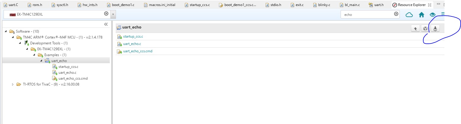
我将“UART_echo”示例导入到 IDE 中:
在示例上执行了“Rebuild”,所有内容都可以编译并正常工作:
****为项目 UART_ECHO 构建配置调试****
"C:\\safeshoot \\applications\ti\\ccsv7\\utils\\bin\\gmake"-k all
'生成文件:./startup_ccs.c'
'调用:ARM 编译器'
"c:/safeshoot/applications/ti/ccsv7/tools/compiler/ti-cgt-arm_16.9.1.LTS/bin/armcl "-mv7M4 -code_state=16 --float_support=FPv4SPD16 --abi=eabi -me -O2 --include_path="C:/safeshoot/applications/ti/ccsv7/tools/compiler/ti-cgt-arm_16.9.1.LTS/include --include_path="C:/ti/tivaware_c_series_2_1_4_178 --advice:power-g --gcc --define=ccs=ccs_pred=ccs_startup --ature=ccs_subsection=ccs_remote_remote_remote_remote_remote_display-ccs=ctrature=ccs_subs=ccs_trature=ccs_trature=ccs_off-code_display_subsection-code.ccs_subs=ccs_remote_display_subsection-code_display_subs=ccs_subsection-code_display_subs=ctradecon_en_tradecon_
"./startup_ccs.c"、第236行:备注#1527-D:(ULP 2.1)检测到使用空循环的 SW 延迟循环。 建议改用计时器模块
"./startup_ccs.c"、第254行:备注#1527-D:(ULP 2.1)检测到使用空循环的 SW 延迟循环。 建议改用计时器模块
"./startup_ccs.c"、第272行:备注#1527-D:(ULP 2.1)检测到使用空循环的 SW 延迟环路。 建议改用计时器模块
'完成构建:./startup_ccs.c'
'
'生成文件:./uart_echo.c'
'调用:ARM 编译器'
"c:/safeshoot/applications/ti/ccsv7/tools/compiler/ti-cgt-arm_16.9.1.LTS/bin/armcl -mv7M4 -code_state=16 --float_support=FPv4SPD16 --abi=eabi -me -O2 --include_path="C:/safeshoot/applications/ti/ccsv7/tools/compiler/ti-cgt-arm_16.9.1.LTS/include --include_path="C:/ti/tivaware_c_series_2_1_4_178 --advice:power=all -g --gcc --define=ccs=ccs_remote_remote_remote_ctrature=ctrature=ctrate-ctrab_code.ctrab_code.c -code_remote_code.combag=ctruart_reat_reate-subs=ctrab_decon_code.c -code.c -trab_reategot_code.c -trab_decon_code.c -code.c -trab_code.c -trab_code.c -trab_code_subs=cus_code.c -code.
"./uart_echo.c"、第202行:备注#1527-D:(ULP 2.1)使用空循环检测到 SW 延迟环路。 建议改用计时器模块
'完成构建:./uart_echo.c'
'
'构建目标:UART_ECHOE.OUT"
'调用:ARM 链接器'
"c:/safeshoot/applications/ti/ccsv7/tools/compiler/ti-cgt-arm_16.9.1.LTS/bin/armcl "-mv7M4 -code_state=16 -float_support=FPv4SPD16 -abi=eabi -me -O2 -advice:pow=all -g -gcc -define=ccs="ccs"-define=part_TM4C129ENCPDT --define=uart_reap_reap_uni_exits=uart_example_intrack-"-rom-"-rom_example_display_unch_example.xml-"-ategot_example_un_un_un_example_display_unch_example.obj-"-"-rom_ov_ov_ov_in_in_over-example_display_over-ature_over-ature_infot_over-uart.track_over-uart.ap_infot_over-uart.ap_over-uart.ap_over-uart.ics"-"-"-"-"-corpage-example.obj_over-example_display_over-in /ti/tivaware_c_series_2_1_4_178/driverlib/ccs/Debug/driverlib.lib /safeshoot/applications/ti/ccsv7/tools/compiler/ti-cgt-arm_16.9.1.LTS/include /safeshoot/applications/ti/ccsv7/tools/compiler/ti-cgt-arm_16.9.1.LTS/lib
备注#10371-D:(ULP 1.1)未检测到使用低功耗模式状态更改指令
'完成的构建目标:UART_ECHOE.OUT"
'
"C:/safeshoot/applications/ti/ccsv7/utils/tiobj2bin/tiobj2bin "UART_ECHO.OUT""UART_ECHO.BIN""C:/safeshoot/applications/ti/ccsv7/tools/compiler/ti-cgt-arm_16.9.1.LTS/bin/armofd "C:/safeshoot/applications/ti/ccsv7/tools/compiler/ti-cgt-arm_16.9.1.LTS/bin/armhex "C:/safeshoot/applications/ti/ccsv7/utils/tiobj2bin/mkhex4bin "
'
****构建完成****
我转到项目属性,将 要我的器件类型从“Tiva TM4C129ENCPDT”更改为“Tiva TM4C129CNCPDT”。
现在项目无法编译,因为现在有4个文件而不是2个:
UART_ECHO_CCS.cmd
startup_ccs.c
tm4c129cncpdt.cmd
tm4c129cncpdt_startup_ccs.c
我删除了前2个、项目编译正常。
我编辑了“tm4c129cncpdt_startup_ccs.c”并进行了两项更改:
添加了:
extern void UARTIntHandler (void);
并更改了:
IntDefaultHandler、 // UART0 Rx 和 Tx
至:
UARTIntHandler、 // UART0 Rx 和 Tx
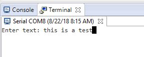
我重建了它,执行了它,并在“UARTIntHandler”过程中放入了一个断点,以查看当我通过串行监视器发送数据时,它会停止-这很好, 但是从串行监视器传递的数据和芯片似乎损坏了-调试开始时,我应该会收到消息:“Enter text:”,但我得到:
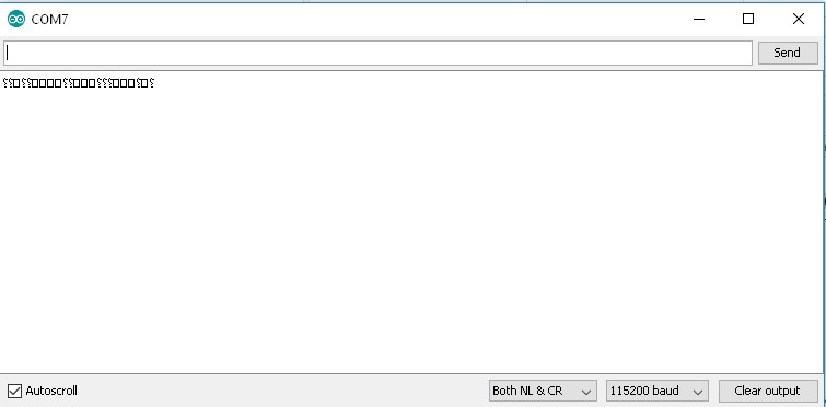
如果我发送任何数据、我更不会将其返回–正如上面所示、就是损坏的字符。
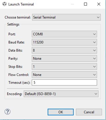
默认情况下、两端通信设置为115200。
为什么这不起作用?