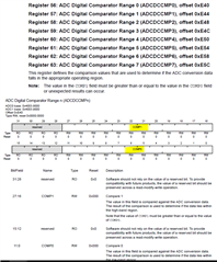
下面是我们针对模拟输入序列发生器的源代码实现。 在处理器启动时调用初始化函数、而 Read_local_inputs 函数被定期调用以获取 ADC 数据。 Low_Voltage_Detection_Entry 和 Nominal _Voltage_Detection_Entry 是用于 ADC0序列0和 ADC1序列0上比较器的函数。 我们观察到+24V、+15V 和驱动温度具有错误的读数。 我们已使用电压探头检查硬件、且处理器获取这些引脚的预期电压、因此我们排除了任何硬件问题。
我们希望您输入可能导致读取错误的内容、或者我们可以采取哪些步骤来解决此问题。
void Analog_Task::Initialize()
{
    Error_Block adc0ss0_eb;
    Error_Block adc1ss0_eb;
#ifndef TEST_HARNESS
    Hwi_Params adc0ss0_hwi_params;
    Hwi_Params adc1ss0_hwi_params;
#endif

    //  Enable ADC0 peripheral
    SysCtlPeripheralEnable( SYSCTL_PERIPH_ADC0 );

    //  Enable ADC1 peripheral
    SysCtlPeripheralEnable( SYSCTL_PERIPH_ADC1 );

    //  Configure trigger sequence to trigger on a processor request
    /*
     * ADC 0 Sequence 0:
     *      -   ADC0AIN1    +24V reference
     *      -   ADC0AIN0    -15V reference
     *      -   ADC0AIN2    +15V reference
     *
     * ADC 0 Sequence 1:
     *      -   ADC0AIN3    +5V reference
     *      -   ADC0AIN13   Drive temperature
     *
     * ADC 1 Sequence 0:
     *      -   ADC1AIN1    +24V reference
     */
    ADCSequenceConfigure( ADC0_BASE, 0, ADC_TRIGGER_PROCESSOR, 0 );
    ADCSequenceConfigure( ADC0_BASE, 1, ADC_TRIGGER_PROCESSOR, 1 );
    ADCSequenceConfigure( ADC1_BASE, 0, ADC_TRIGGER_ALWAYS, 0 );

    //  Setup the ADC0 read sequence 0
    ADCSequenceStepConfigure( ADC0_BASE, 0, 0, ADC_CTL_CH1 | ADC_CTL_CMP0 );
    ADCSequenceStepConfigure( ADC0_BASE, 0, 1, ADC_CTL_CH1 | ADC_CTL_CMP0 );
    ADCSequenceStepConfigure( ADC0_BASE, 0, 2, ADC_CTL_CH0 );
    ADCSequenceStepConfigure( ADC0_BASE, 0, 3, ADC_CTL_CH0 );
    ADCSequenceStepConfigure( ADC0_BASE, 0, 4, ADC_CTL_CH2 );
    ADCSequenceStepConfigure( ADC0_BASE, 0, 5, ADC_CTL_CH2 | ADC_CTL_IE | ADC_CTL_END );

    //  Setup the ADC0 read sequence 1
    ADCSequenceStepConfigure( ADC0_BASE, 1, 0, ADC_CTL_CH3 );
    ADCSequenceStepConfigure( ADC0_BASE, 1, 1, ADC_CTL_CH3 );
    ADCSequenceStepConfigure( ADC0_BASE, 1, 2, ADC_CTL_CH13 );
    ADCSequenceStepConfigure( ADC0_BASE, 1, 3, ADC_CTL_CH13 | ADC_CTL_IE | ADC_CTL_END );

    //  Setup the ADC1 read sequence 0
    ADCSequenceStepConfigure( ADC1_BASE, 0, 0, ADC_CTL_CH1 | ADC_CTL_CMP0 | ADC_CTL_END );

    //  Setup the 24V comparator low voltage trigger
    ADCComparatorConfigure( ADC0_BASE, 0, ADC_COMP_INT_LOW_HONCE );
    ADCComparatorRegionSet( ADC0_BASE, 0, LOW_TRIGGER_ADC_COUNTS, NOMINAL_TRIGGER_ADC_COUNTS );

    //  Setup the 24V comparator recovery trigger
    ADCComparatorConfigure( ADC1_BASE, 0, ADC_COMP_INT_HIGH_HONCE );
    ADCComparatorRegionSet( ADC1_BASE, 0, LOW_TRIGGER_ADC_COUNTS, NOMINAL_TRIGGER_ADC_COUNTS );

    //  Clear the comparator data
    ADCComparatorReset( ADC0_BASE, 0, true, true );
    ADCComparatorReset( ADC1_BASE, 0, true, true );

    //  Create a Hwi for ADC0 sequence 0
    Error_init( &adc0ss0_eb );
    Hwi_Params_init( &adc0ss0_hwi_params );
    Hwi_construct( &( adc0ss0_hwi_struct ),
                   INT_ADC0SS0,
                   Analog_Task::Low_Voltage_Detection_Entry,
                   &adc0ss0_hwi_params,
                   &adc0ss0_eb );

    //  Create a Hwi for ADC1 sequence 0
    Error_init( &adc1ss0_eb );
    Hwi_Params_init( &adc1ss0_hwi_params );

    //  Set the low voltage interrupt to the highest priority (0)
    adc1ss0_hwi_params.priority = 0;
    Hwi_construct( &( adc1ss0_hwi_struct ),
                   INT_ADC1SS0,
                   Analog_Task::Nominal_Voltage_Detection_Entry,
                   &adc1ss0_hwi_params,
                   &adc1ss0_eb );

    //  Enable the comparator interrupts
    ADCComparatorIntEnable( ADC0_BASE, 0 );
    ADCComparatorIntEnable( ADC1_BASE, 0 );

    //  Clear any pending interrupts
    ADCIntClear( ADC0_BASE, 0 );
    ADCIntClear( ADC1_BASE, 0 );

    //  Enable the sequences
    ADCSequenceEnable( ADC0_BASE, 0 );
    ADCSequenceEnable( ADC0_BASE, 1 );
    ADCSequenceEnable( ADC1_BASE, 0 );

    //  Enable the comparator interrupt sources
    ADCIntEnableEx( ADC0_BASE, ADC_INT_DCON_SS0 );
    ADCIntEnableEx( ADC1_BASE, ADC_INT_DCON_SS0 );

    //  Enable the comparator interrupts
    ADCIntEnable( ADC1_BASE, 0 );
    ADCIntEnable( ADC1_BASE, 0 );

    //  Enable the ADC0 sequence 0 interrupt
    IntEnable( INT_ADC0SS0 );

    //  Enable the ADC1 sequence 0 interrupt
    IntEnable( INT_ADC1SS0 );
    //  Assert the low power detection pin to notify DSP nominal voltage is detected
    GPIO_Out_HI( LOW_POWER_DET );
}

void Analog_Task::Read_Local_Inputs()
{
    //  Clear the interrupt mask
    ADCIntClear( ADC0_BASE, 0 );
    ADCIntClear( ADC0_BASE, 1 );

    //  Trigger the analog read
    ADCProcessorTrigger( ADC0_BASE, 0 );
    ADCProcessorTrigger( ADC0_BASE, 1 );

    //  Wait for reads to complete
    while ( !ADCIntStatus( ADC0_BASE, 0, false ) )
    {
    }
    while ( !ADCIntStatus( ADC0_BASE, 1, false ) )
    {
    }
    //  Grab the latest input readings
    ADCSequenceDataGet( ADC0_BASE, 0, m_adc0_seq0 );
    ADCSequenceDataGet( ADC0_BASE, 1, m_adc0_seq1 );
}

void Analog_Task::Low_Voltage_Detection_Entry( UArg )
{
    uint32_t adc_comparator_status;

    //  Get the interrupt status
    adc_comparator_status = ADCComparatorIntStatus( ADC0_BASE );

    //  Clear the asserted interrupts
    ADCComparatorIntClear( ADC0_BASE, adc_comparator_status );

    //  Inactivate the warehouse task
    //  TODO - Need to add back in once on production board
    //Task_setPri( g_wh_task_handle, -1 );

    //  De-assert the low power detection pin to notify DSP low voltage is detected
    GPIO_Out_LO( LOW_POWER_DET );
}

void Analog_Task::Nominal_Voltage_Detection_Entry( UArg )
{
    uint32_t adc_comparator_status;

    //  Get the interrupt status
    adc_comparator_status = ADCComparatorIntStatus( ADC1_BASE );

    //  Clear the asserted interrupts
    ADCComparatorIntClear( ADC1_BASE, adc_comparator_status );

    //  Activate the warehouse task
    //  TODO - Need to add back in once on production board
    //Task_setPri( g_wh_task_handle, WAREHOUSE_TASK_PRIORITY );

    //  Assert the low power detection pin to notify DSP nominal voltage is detected
    GPIO_Out_HI( LOW_POWER_DET );
}


