请注意,本文内容源自机器翻译,可能存在语法或其它翻译错误,仅供参考。如需获取准确内容,请参阅链接中的英语原文或自行翻译。
器件型号:TMS570LS3137 您好!
我无法使用 XDS100 V2调试器对我的设备进行编程。
我检查了连接
我检查了我的3V3和1V2电压
我使用了另一个 PCB 检查了调试器,它工作正常
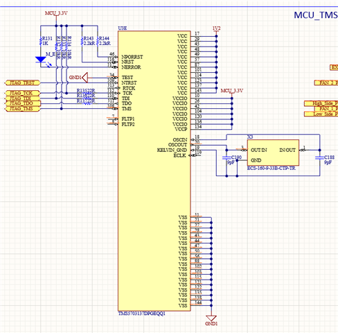
我检查了 晶振时钟信号,它是16 MHz
我不知道这个问题,你能帮我吗...
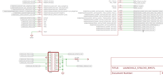
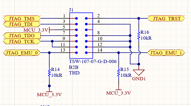
我将在下面添加 JTAG 连接原理图。
您好!
我无法使用 XDS100 V2调试器对我的设备进行编程。
我检查了连接
我检查了我的3V3和1V2电压
我使用了另一个 PCB 检查了调试器,它工作正常
我检查了 晶振时钟信号,它是16 MHz
我不知道这个问题,你能帮我吗...
我将在下面添加 JTAG 连接原理图。