请注意,本文内容源自机器翻译,可能存在语法或其它翻译错误,仅供参考。如需获取准确内容,请参阅链接中的英语原文或自行翻译。
器件型号:TLV320AIC3204EVM-K 工具/软件:
您好!
我用手将编解码器板从 TLV320评估套件连接到我的 Nordic Semiconductor 处理器 Devkit、以测试编解码器、到目前为止、我完全无法使其发出声音、除非耳机初始化时出现爆裂声。 我将从电源将3.3V 电压馈入3.3V 网络并馈入 HPVDD/LDOIN、我可以确保开关和所有条件都已正确设置、以将内部 LDO 用于 DVDD 和 AVDD。 如果我使用万用表测量电路板上的一些点:LDO_SEL ~3.3V、IOVDD ~3.3V、DVDD 为1.708V、AVDD 为1.704V。 大多数情况下、我都通过 I2C 成功与 IT 进行通信、但在某些加电时出现了写入或回读故障。
我尝试将其配置为在没有 PLL 的6.144MHz MCLK 信号的情况下以48kHz 运行、然后使用蜂鸣发生器发出一些声音、即使只有 I2C 命令和时钟输入正常、但迄今为止仍然没有。
我已经尝试过移动配置命令、以便它们发生在 MCLK 处于活动状态之前或之后、现在我可以在 MCLK 切换一段时间后全部发生。
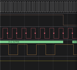
相关设置代码位于下面的代码块中、我附加了一个 Saleae 捕获、显示了所有信号的运行情况(I2C、MCLK、BCLK、LRCLK (WCLK)、DIN、 复位)。
请帮助! 我试图尽快使其正常工作、以验证我们的硬件设计。
谢谢、
Glen
k_sleep(K_MSEC(1000));
retcode |= tlv320_write(0, 0x01, 0x01); // Software reset
k_sleep(K_MSEC(100));
// === CLOCK SETUP for MCLK = 6.144 MHz ===
// We will use MCLK directly, so PLL is not needed
while (tlv320_write(0, 0x04, 0x00)); // CODEC_CLKIN = MCLK
// NDAC = 1, MDAC = 2 for 6.144 MHz -> 48 kHz with DOSR = 128
while (tlv320_write(0, 0x0B, 0x01)); // NDAC = 1
while (tlv320_write(0, 0x0C, 0x01)); // MDAC = 1
while (tlv320_write(0, 0x0D, 0x00)); // DOSR MSB = 0
while (tlv320_write(0, 0x0E, 0x80)); // DOSR LSB = 128
// Interface settings
while (tlv320_write(0, 0x1B, 0x00)); // I2S, 16-bit word length
// while (tlv320_write(0, 0x1D, 0x01); // low bits: 00: BDIV_CLKIN = DAC_CLK, 01: BDIV_CLKIN = DAC_MOD_CLK
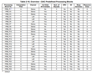
while (tlv320_write(0, 0x3C, 0x08)); // DAC processing block = PRB_P8
// Enable Master Analog Power:
while (tlv320_write(1, 0x01, 0x08)); // Disable crude AVDD
// Enable internal LDO:
while (tlv320_write(1, 0x02, 0x01)); // Enable AVDD LDO with analog blocks powerered up
while (tlv320_write(1, 0x7B, 0x01)); // REF charging time = 40ms
while (tlv320_write(1, 0x14, 0x25)); // HP soft stepping config
while (tlv320_write(1, 0x0A, 0x00)); // Common mode settings
// Route DAC outputs
while (tlv320_write(1, 0x0C, 0x08)); // Route Left DAC to HPL
while (tlv320_write(1, 0x0D, 0x08)); // Route Right DAC to HPR
// Class AB amplifier setup
while (tlv320_write(1, 0x03, 0x00)); // PTM mode for DAC
while (tlv320_write(1, 0x04, 0x00));
// Set output volume
while (tlv320_write(1, 0x10, 0x14)); // HPL gain = 10dB
while (tlv320_write(1, 0x11, 0x14)); // HPR gain = 10dB
while (tlv320_write(1, 0x09, 0x30)); // Power up HPL and HPR drivers
k_sleep(K_MSEC(2500)); // TLV320 app guide says to wait 2.5 seconds for soft stepping to take effect to avoid pops
// Page 0 DAC power-up
while (tlv320_write(0, 0x3F, 0xD6)); // Power up both DACs, route L/R channels
while (tlv320_write(0, 0x40, 0x00)); // Unmute DAC
// Test beep
LOG_ERR("TLV320 BEEP START");
retcode |= tlv320_quick_write(0, 0x49, 0x5F); // MSB
retcode |= tlv320_quick_write(0, 0x4A, 0x00); // MID
retcode |= tlv320_quick_write(0, 0x4B, 0x00); // LSB
retcode |= tlv320_quick_write(0, 0x48, 0x00);
retcode |= tlv320_quick_write(0, 0x47, 0x80);
}