Other Parts Discussed in Thread: TAC5111
请注意,本文内容源自机器翻译,可能存在语法或其它翻译错误,仅供参考。如需获取准确内容,请参阅链接中的英语原文或自行翻译。
器件型号: TAC5111
您好、
我们将在 i.MX8M Plus 的新设计中使用 TAC5111。
为了进行播放、我们有 1 个模拟扬声器、其放大器连接到 OUT1P/OUT1M。
为了进行录音、我们在引脚 GPIO2(时钟)和 GPIO1(数据)上有 2 个 PDM 麦克风。
麦克风配置为交替时钟相位。 这通过连接双通道示波器并在每个相位期间看到脉冲来确认。
与 CPU 的接口是针对 I2S 配置的、对于本问题、我们在每个通道 16 位的速率下进行记录。 编解码器相应地通过 amixer 命令进行配置、对于 2 通道数字 PDM 输入:
amixer -c 0 sset 'IN1 Source Mux' 'PDM'
amixer -c 0 sset 'IN2 Source Mux' 'PDM'
amixer sset 'ASI_TX_CH1_EN' cap
amixer sset 'ASI_TX_CH2_EN' cap
amixer sset 'PDM1 Digital' 255

# must record in S16_LE format to avoid driver bugs
amixer sset 'PDM Clk Divider' '1.4112 MHz or 1.536 MHz'
arecord -D hw:0,0 -c 2 -r 48000 -f S16_LE -d 15 rec.wav
因为我们运行的是 NXP 供应商内核版本 6.6 、所以我们使用的编解码器驱动程序 git.ti.com/.../ 的标题为“使驱动程序与内核版本 5.15 兼容“。
我们发现录制的文件在第二个通道上具有静音状态、只有一个通道具有有效的波形。 事实上,单通道录音是通过在录音时播放音乐,然后回放录制的文件确认的。
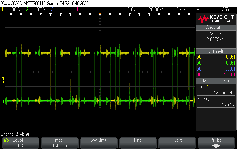
我们使用示波器测量 I2S 信号:FCLK 为 48kHz、BCLK 为 1.536MHz。
但是、数据(DOUT 引脚)在 FCLK 为高电平时保持低电平、即未处于高电平状态 FCLK、编解码器不会通过 I2S 发送数据到 CPU(请参阅下面的测量结果 — 由于 GND 悬空,因此略有噪声):
为什么会这样、我们如何配置编解码器以将第二个通道数据从 PDM 麦克风发送到 I2S?
有关以下参考器件树片段:
/ {
	sound-tac5111 {
		/*
		 * TAC5111 Codec on i.MX8 SAI3 with 4-wire i2s interface.
		 *
		 * - SoC generates MCLK for Codec at 24.576
		 *   (avoids clock drift between SoC and Codec)
		 * - SoC is bitclock and frame master
		 * - I2S interface width max. S32_LE
		 * - Codec GPIO1 & GPIO2 with dual PDM microphone
		 * - Codec OUT1P/OUT1M differential mono output
		 *   routed to speaker through amplifier
		 *
		 */
		compatible = "simple-audio-card";
		simple-audio-card,format = "i2s";
		simple-audio-card,name = "Analog";
		simple-audio-card,bitclock-master = <&cpu_dai>;
		simple-audio-card,frame-master = <&cpu_dai>;

		simple-audio-card,widgets =
			"Line", "Line In",
			"Line", "Line Out";

		simple-audio-card,routing =
			"DIN1", "Line In",
			"DIN2", "Line In",
			"Line Out", "OUT1";

		cpu_dai: simple-audio-card,cpu {
			sound-dai = <&sai3>;
			/* TODO: clock rate? */
			/* ensure mclk is generated by SoC for Codec */
			//system-clock-direction-out;
			/* force 32-bit slots */
			//dai-tdm-slot-num = <2>;
			//dai-tdm-slot-width = <32>;
		};

		codec_dai: simple-audio-card,codec {
			sound-dai = <&codec>;
			/* this ensures codec set_sysclk call-back executes */
			system-clock-frequency = <24576000>;
			mclk-fs = <512>;
		};
	};
};

&i2c2 {
	codec: audio-codec@50 {
		compatible = "ti,tac5111";
		reg = <0x50>;
		#sound-dai-cells = <0>;
		pinctrl-names = "default";
		pinctrl-0 = <&pinctrl_codec>;
		interrupts-extended = <&gpio4 21 IRQ_TYPE_EDGE_FALLING>;
		avdd-supply = <&v_3_3>;
		iovdd-supply = <&v_3_3>;
		/*
		 * configure gpio functionality on gpio pins:
		 * - GPIO1: pdm data input
		 * - GPIO2: pdm clock output
		 * - GPO1:  chip irq output
		 */
		ti,gpios-func = <1>, <4>, <3>;
		/*
		 * select pdm input pins for channels 1/2 & 3/4:
		 * - ch0/1: gpio1
		 * - ch2/3: not used
		 */
		ti,pdm-input-pins = <1>, <0>;
		/* configure gpi1 as cclk input */
		ti,gpi1-func = <2>;
		/*
		 * configure MICBIAS and VREF to fix driver probe error:
		 * [    8.570840] tac5x1x-codec 1-0050: Fail to get verf E:-22
		 *
		 * Yet bindings clearly state to that these are powered down if "node" (read property) omitted:
		 * - "If node is omitted then MicBias is powered down."
		 * - "If node is omitted then VREF is powered down."
		 * This board does not use them ...
		 */
		ti,vref = <0>;
		ti,micbias-vg = <3>;
		/* configure gpi(o) drive:
		 * - GPIO1: floating, i.e. output buffer disabled
		 * - GPIO2: push-pull, i.e. active low & active high (PDM clock)
		 * - GPO1:  open-drain, i.e. active low & high impedance
		 */
		ti,gpios-drive = <0>, <1>, <3>;
		ti,gpa-gpio = <0>;
		ti,gpa-threshold = <75>, <186>;
	};
};