主题中讨论的其他器件:PCM5121、
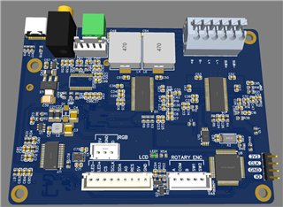
场景:PCB、具有2个 TAS5755和1个 PCM5121、提供 I2S 24位48kHz 的 MCLK (512xfs)、BCLK、LRCLK 和 SDATA。
当 PVDD 电压介于15V 和24V 之间时、TAS5755M 会出现问题。 我设计了一个具有两个 TAS5755M 放大器的 PCB。 一个(标记为 AmpLR)用于2.0 BD 模式的立体声扬声器。 另一个 TAS (标记为 AmpSUB)用于 PBTL BD 配置中的低音炮。 当 PVDD 由12V 电源供电时、一切工作正常。 切换到24V 电源时、AmpLR TAS 无法正常启动、而 AmpSUB 没有问题。
查看 I2C 寄存器、可以看出 I2C 地址在启动期间未正确锁存或 TAS 复位。 AmpSub 正在获取 AmpLR 配置。 将配置延迟几秒钟、无法解决问题、然后两个芯片的寄存器均已正确配置、但 AmpLR TAS 没有声音。 我真的不明白:除了 PBTL 配置外、两个芯片的设计几乎是相同的。
我迄今确定的是:
使用可变电源、启动电压小于15V、然后在配置后增加电压、一切都按预期工作。
2.仅提供 AVDD 和 VDD、无 PVDD (PVDD 断开连接)、配置 TAS5755M、然后仅应用 PVDD、一切都按预期工作。
我意识到数据表特别提到了电源定序、但在研究了 EVM 的原理图之后、它似乎并不那么重要、因为 EVM 没有根据数据表提供适当的定序。 PCB 使用相同的 PVDD 输入、将微处理器和 TAS5755M 的电压降至5V 和3V。 因此、PVDD 可能会在 AVDD 和 VDD 达到3.3V 之前提供。
有人能不能告诉我为什么会出现这种奇怪的行为。
我也注意到的另一个问题是、如果没有提供 MCLK、TAS5755将无法实现 PLL 锁定、尽管数据表提到它应该在没有 MCLK 的情况下工作。 PCB 上的 PCM5121无需 MCLK 即可锁定、但需要手动时钟配置。 I2S 由 XMOS 分线板供电。
在此配置中:
bool TAS5755::initialize()
{
    bool result = true;
    result &= writeRegister(0x1b, 0x00);  //Set oscillator trim to factory calibrated
    ThisThread::sleep_for(50ms);
    result &= writeRegister(0x05, 0x48);  //Enter all channel shutdown
    ThisThread::sleep_for(10ms);
    result &= writeRegister(0x10, 0x07);  //Set Max PWM duty cycle for >18v power supply
    result &= writeRegister(0x02, 0x00);  //Clear errors
    result &= writeRegister(0x03, 0x80);  //Soft unmute
    result &= writeRegister(0x0e, 0x92);  //Slow volume slew rate
    result &= writeRegister(0x11, 0xb8);  //Set timings for BD 2.0 mode
    result &= writeRegister(0x12, 0x60);
    result &= writeRegister(0x13, 0xa0);
    result &= writeRegister(0x14, 0x48);
    uint8_t bufTimings[4] = { 0x00, 0x89, 0x77, 0x72 }; //Set multiplexer for BD 2.0 mode
    result &= writeRegister(0x20, bufTimings, 4);
    if (pbtl)
    {
        //p24 9.3.3 PBTL www.ti.com/.../tas5755m.pdf
        uint8_t bufMux[4] = { 0x01, 0x10, 0x32, 0x45 };
        result &= writeRegister(0x25, bufMux, 4); //PWM MUX
        result &= writeRegister(0x19, 0x35);  //Shutdowns
        //e2e.ti.com/.../tas5755m-asking-for-the-tas5755-pbtl-and-the-drc-setting
        uint8_t bufCh4Src[4] = { 0x00, 0x00, 0x42, 0x03 };
        result &= writeRegister(0x21, bufCh4Src, 4); //CH4 Source Select
        uint8_t bufCh4InputMixer[8] = { 0x00, 0x40, 0x00, 0x00, 0x00, 0x40, 0x00, 0x00 };
        result &= writeRegister(0x61, bufCh4InputMixer, 8); //CH4 Input Mixer
        uint8_t bufCh2OutputMixer[12] = { 0x00, 0x00, 0x00, 0x00, 0x00, 0x00, 0x00, 0x00, 0x00, 0x80, 0x00, 0x00 };
        result &= writeRegister(0x52, bufCh2OutputMixer, 12); //CH2 Output Mixer

        //Biquad 0x5a and 0x5b registers (BQ4a on GUI) can used for DSP
    }
    ThisThread::sleep_for(250ms);
    result &= writeRegister(0x05, 0x08);  //Exit all channel shutdown

    return result;
}

...
TAS5755 amplr(&audioI2C, AMPLR_ADDR); //Start in BTL mode, addr: 0x34
TAS5755 ampsub(&audioI2C, AMPSUB_ADDR, true); //Start in PBTL mode: addr: 0x36

main.cpp
{

  AmpLrPowerDown = 0;
  AmpSubPowerDown = 0;
  ThisThread::sleep_for(10ms);
  AmpLrPowerDown = 1;
  AmpSubPowerDown = 1;
  ThisThread::sleep_for(10ms);
  AmpReset = 1;
  ThisThread::sleep_for(250ms);
  amplr.initialize();
  amplr.setVolume(-6.0f);
  ThisThread::sleep_for(100ms);
  ampsub.initialize();
  ampsub.setVolume(-6.0f);
}
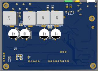
我不确定输出电感器是否可能存在与 TAS 芯片太近的 EMI 干扰? 所附为原理图。