

请注意,本文内容源自机器翻译,可能存在语法或其它翻译错误,仅供参考。如需获取准确内容,请参阅链接中的英语原文或自行翻译。
器件型号:TLV320AIC3204EVM-K 您好!
我使用3204EVM 套件调试和测试 AGC。 我使用套件中的 P23接口供电、使用外部 IC 通过 I2C 更改寄存器、IN1L 的 MIC 输入、在 HPL 和 HPR 的 AGC 输出之后提供 MCLK、WCLK、BCLK、SDA、SCL。 现在我有几个问题:
1.测试并发现它有较大的白色背景噪声、但 PGA 模拟旁路没有太多的白色背景噪声。 有什么方法可以解决这个问题吗?
请参阅我使用 TLV320测得的压缩曲线。 它一开始的 MIC 输入为64、输出为74、这相当于增益为10 (假设最大 AGC 增益设置为10)。 在中间阶段、如果未达到目标电平、但测量的曲线未达到、甚至开始压缩、则应添加最大 AGC 增益输出。 出什么问题了吗? 如下所示: 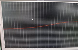
以下是我使用的寄存器设置:
###############################################
# Software Reset
###############################################
#
# Select Page 0
w 30 00 00
#
# Initialize the device through software reset
w 30 01 01
#
###############################################

###############################################
# Clock Settings
# ---------------------------------------------
#The input clock signal : MCLK = 11.2896 MHz,BLCK = 1.4 MHz, WCLK = 44.1 kHz
###############################################
#
# Select Page 0
w 30 00 00
#
# NADC = 1, MADC = 2
w 30 12 81 82
#
###############################################

###############################################
AGC
###############################################
w 30 00 00
w 30 57 7E
w 30 56 A0
w 30 58 64
w 30 59 08
w 30 5A 32
w 30 5B 00
w 30 5C 06
###############################################

###############################################
# Enable Loopback Page 0 register 29
###############################################
#
# Loopback enable for stereo audio data
w 30 1D 30
#
###############################################

###############################################
# Signal Processing Settings
###############################################
#
# Select Page 0
w 30 00 00
#
# Set the ADC Mode to PRB_P1
w 30 3d 01
#
###############################################

###############################################
# Initialize Codec
###############################################
#
# Select Page 1
w 30 00 01
#
# Disable weak AVDD in presence of external
# AVDD supply
w 30 01 08
#
# Enable Master Analog Power Control
w 30 02 00
#
# Select ADC PTM_R4
w 30 3d 00
#
# Set the input powerup time to 3.1ms (for ADC)
w 30 47 32
#
# Set the REF charging time to 40ms
w 30 7b 01
#
###############################################

###############################################
# Recording Setup
###############################################
#
# Select Page 1
w 30 00 01
# MICBIAS
w 30 33 50
# Route IN3L to LEFT_P with 10K input impedance
w 30 34 04
#
w 30 36 04
#
w 30 37 00
#
w 30 39 00
#
w 30 3b 0c
w 30 3c 0c
#
# Select Page 0
w 30 00 00
#
# Power up LADC/RADC
w 30 51 c0
#
# Unmute LADC/RADC
w 30 52 00
#
###############################################

###############################################
# Clock Settings
# ---------------------------------------------
# The input clock signal : MCLK = 11.2896 MHz,BLCK = 1.4 MHz, WCLK = 44.1 kHz: MCLK = 11.2896 MHz,
###############################################
#
# Select Page 0
w 30 00 00
#
# NDAC = 1, MDAC = 2
w 30 0b 81 82
#
###############################################

###############################################
# Signal Processing Settings
###############################################
#
# Select Page 0
# w 30 00 00
#
# Set the DAC Mode to PRB_P8
w 30 3c 08
#
###############################################

###############################################
# Playback Setup
###############################################
#
# Select Page 1
w 30 00 01
#
# De-pop
w 30 14 25
#
# Route LDAC/RDAC to HPL/HPR
w 30 0c 08 01
#
w 30 0e 00 00
#
w 30 09 30
#
# Unmute HPL/HPR driver, 0dB Gain
w 30 10 00 00
w 30 12 00 00
#
# Select Page 0
w 30 00 00
#
# DAC => 0dB
w 30 41 00 00
#
# Power up LDAC/RDAC
w 30 3f d6
#
# Unmute LDAC/RDAC
w 30 40 00
#
###############################################
