请注意,本文内容源自机器翻译,可能存在语法或其它翻译错误,仅供参考。如需获取准确内容,请参阅链接中的英语原文或自行翻译。
器件型号:TLV320AIC3120 您好!
我尝试过来自论坛和互联网的不同示例代码、但 无法从扬声器获得任何输出。
以下是我准备的命令并与数据表相关联、所有 I2C 命令都会正常执行并通过读回来确认写入。
以下是所执行的写入序列。
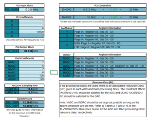
// Clock-gen muxing. PLL_CLKIN=MCLK, CODEC_CLKIN=PLL_CLK 12.288MHZ
// P=1, R=1, J=6, D=10000,
// NDAC=NADC=7, MDAC=MADC=3,
// DOSR=AOSR=384 => 16KHz fs
static const tlv_cmd_t init_cmd[] = {
{0x00, 0x00}, // Page 0
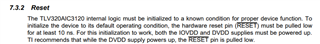
{0x01, 0x01}, // sw reset
// PLL config
{0x04, 0x03}, // Clock-gen Mux. PLL_CLKIN=MCLK, CODEC_CLKIN=PLL_CLK
{0x05, 0x91}, // PLL P+R. PLL power up, P=1, R=1 (P=divider,R=multiplier)
{0x06, 0x06}, // PLL J = 6
{0x07, 0x27}, // PLL D fractional. D-value MSB = 0x27
{0x08, 0x10}, // PLL D fractional. D-value LSB = 0x10
// mode master
{0x1B, 0x0C}, // mode is i2s master, wordlength is 16, BCLK/WCLK out
// divider configs
{0x0B, 0x87}, // NDAC is powered up and set to 7
{0x0C, 0x82}, // MDAC is powered up and set to 2
{0x0D, 0x01}, // DOSR = 384 0x180, DOSR(9:8) = 0x01
{0x0E, 0x80}, // DOSR = 384 0x180, DOSR(7:0) = 0x80
{0x12, 0x00}, // NADC divider is powered down and ADC_DSP_CLK = DAC_DSP_CLK.
{0x13, 0x00}, // MADC divider is powered down and ADC_MOD_CLK = DAC_MOD_CLK.
{0x14, 0x00}, // AOSR = 256 0x100, AOSR(7:0) = 0
//
{0x74, 0x00}, // DAC => volume control thru pin disable
{0x44, 0x00}, // DAC => drc disable, th and hy
{0x41, 0x00}, // DAC => 0 db gain left
//
{0x00, 0x01}, // Page 1
{0x21, 0x4E}, // De-pop, Power on = 800 ms, Step time = 4 ms
{0x1F, 0x84}, // HPL
{0x23, 0x40}, // LDAC routed to HPL
{0x28, 0x0E}, // HPL unmute and gain 1dB
{0x24, 0x00}, // No attenuation on HP
{0x25, 0x00},
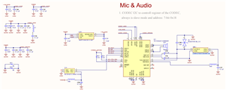
{0x2E, 0x0A}, // MIC BIAS = 2.5v
{0x30, 0x40}, // MICPGA P = MIC M 10K
{0x31, 0x10}, // MICPGA N = MIC N 10K
//
{0x00, 0x00}, // Page 0
{0x3C, 0x0B}, // select DAC DSP mode 11 & enable adaptive filter
//
{0x00, 0x08},
{0x01, 0x04},
//
{0x00, 0x00},
{0x3F, 0x96}, // POWERUP DAC (soft step disable)
{0x40, 0x04}, // Unmute DAC
{0x51, 0x80}, // Powerup ADC channel
{0x52, 0x00}, // Unmute ADC channel
//
{0x00, 0x01},
{0x2A, 0x1C}, // Unmute Class-D left
{0x20, 0xC6}, // Power-up Class-D drivers
};
static const tlv_cmd_t loop_back_cmd[] = {
{0x00, 0x00}, // Page 0
{0x1d, 0x1d}, // b4 = ADC-to-DAC loopback enabled
{0x00, 0x01},
{0x2e, 0x0a}, // MICBIAS = 2.5V
{0x26, 0x4c},
};
static const tlv_cmd_t beep_cmd[] = {
{0x00, 0x00}, // Page 0
{0x40, 0x0C}, // mute DACs
{0x0B, 0x07}, // power down NDAC divider
{0x47, 0x80}, // enable beep generator with left channel volume = 0dB
{0x49, 0x00}, // BeepLen HIGH
{0x4A, 0x7D}, // BeepLen MID
{0x4B, 0xA0}, // BeepLen LOW
{0x4C, 0x59}, // BeepSin MSB
{0x4D, 0x98}, // BeepSin LSB
{0x4E, 0x59}, // BeepCos MSB
{0x4F, 0x98}, // BeepCos LSB
{0x0B, 0x87}, // NDAC is powered up and set to 7
{0x40, 0x04}, // Unmute DAC
};下面是对 UCC28780
 。
。
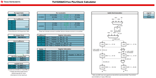
下面是 PLL 计算