This thread has been locked.

If you have a related question, please click the "Ask a related question" button in the top right corner. The newly created question will be automatically linked to this question.

[参考译文] CC2640R2F:双功能使用DIO8作为GPIO,DIO8 MOSI无法打开SPI?

Guru**** 2625255 points

Other Parts Discussed in Thread: CC2640R2F

请注意,本文内容源自机器翻译,可能存在语法或其它翻译错误,仅供参考。如需获取准确内容,请参阅链接中的英语原文或自行翻译。

https://e2e.ti.com/support/wireless-connectivity/bluetooth-group/bluetooth/f/bluetooth-forum/1098146/cc2640r2f-dual-functionality-use-dio8-as-gpio-and-dio8-mosi-not-able-to-open-spi

部件号:CC2640R2F

您好,

我目前正在使用CC2640R2F和NXP NTM88执行TPMS项目。 DIO8具有双重功能,可用作GPIO线路,从 高到低转换。 之后,我将DIO8初始化为SPI MOSI引脚。 打开SPI调用SPI_open()时出现问题,没有句柄。 我正在使用“spimaster”示例程序作为基础。

BoardGpioInitTable[],位于CC2640R2F_LAUNCXL.c.

const PIN_Config BoardGpioInitTable[] = {

    CC2640R2_LAUNCHXL_PIN_RLED | PIN_GPIO_OUTPUT_EN | PIN_GPIO_HIGH | PIN_PUSHPULL | PIN_DRVSTR_MAX,       /* LED initially on */
    CC2640R2_LAUNCHXL_PIN_GLED | PIN_GPIO_OUTPUT_EN | PIN_GPIO_LOW | PIN_PUSHPULL | PIN_DRVSTR_MAX,       /* LED initially off */
    //CC2640R2_LAUNCHXL_PIN_BTN1 | PIN_INPUT_EN | PIN_PULLUP | PIN_IRQ_BOTHEDGES | PIN_HYSTERESIS,          /* Button is active low */
    //CC2640R2_LAUNCHXL_PIN_BTN2 | PIN_INPUT_EN | PIN_PULLUP | PIN_IRQ_BOTHEDGES | PIN_HYSTERESIS,          /* Button is active low */
    CC2640R2_LAUNCHXL_SPI_FLASH_CS | PIN_GPIO_OUTPUT_EN | PIN_GPIO_HIGH | PIN_PUSHPULL | PIN_DRVSTR_MIN,  /* External flash chip select LOW disabled */
    //CC2640R2_LAUNCHXL_SPI0_CSN | PIN_GPIO_OUTPUT_EN | PIN_GPIO_HIGH | PIN_PUSHPULL | PIN_DRVSTR_MIN,      /* NTM88 chip select */
    CC2640R2_LAUNCHXL_UART_RX | PIN_INPUT_EN | PIN_PULLDOWN,                                              /* UART RX via debugger back channel */
    CC2640R2_LAUNCHXL_UART_TX | PIN_GPIO_OUTPUT_EN | PIN_GPIO_LOW | PIN_PUSHPULL,                         /* UART TX via debugger back channel */
    CC2640R2_LAUNCHXL_DIO21 | PIN_INPUT_EN | PIN_PULLUP | PIN_IRQ_NEGEDGE | PIN_HYSTERESIS,               /* Wake Up pin driven by NTM88 */
    CC2640R2_LAUNCHXL_SPI0_MOSI | PIN_GPIO_OUTPUT_EN | PIN_GPIO_HIGH | PIN_PUSHPULL | PIN_DRVSTR_MAX,     /* Configure MOSI first as output for NTM88 KBI input */
    //CC2640R2_LAUNCHXL_SPI0_MOSI | PIN_INPUT_EN | PIN_PULLDOWN,                                            /* SPI master out - slave in */
    CC2640R2_LAUNCHXL_SPI0_MISO | PIN_INPUT_EN | PIN_PULLDOWN,                                            /* SPI master in - slave out */
    CC2640R2_LAUNCHXL_SPI0_CLK | PIN_INPUT_EN | PIN_PULLDOWN,                                             /* SPI clock */

    PIN_TERMINATE
};

NTM88PinTable[]在spimaster.c处

/*
 * Application button pin configuration table:
 *   - Buttons interrupts are configured to trigger on falling edge.
 */
PIN_Config NTM88PinTable[] = {
    Board_PIN_LED0 | PIN_GPIO_OUTPUT_EN | PIN_GPIO_HIGH | PIN_PUSHPULL | PIN_DRVSTR_MAX,     /* LED initially on */
    Board_PIN_LED1 | PIN_GPIO_OUTPUT_EN | PIN_GPIO_LOW | PIN_PUSHPULL | PIN_DRVSTR_MAX,      /* LED initially off */
    //Board_NTM88_SPI_CS | PIN_GPIO_OUTPUT_EN | PIN_GPIO_HIGH | PIN_PUSHPULL | PIN_DRVSTR_MIN, /* NTM88 chip select */
    //Board_NTM88_SCLK | PIN_INPUT_EN | PIN_PULLDOWN,                                          /* SPI clock */
    Board_NTM88_MOSI | PIN_GPIO_OUTPUT_EN | PIN_GPIO_HIGH | PIN_PUSHPULL | PIN_DRVSTR_MAX,   /* Configure MOSI first as output for NTM88 KBI input */
    //Board_NTM88_MISO | PIN_INPUT_EN | PIN_PULLDOWN,                                          /* SPI master MISO */
    Board_WAKE_UP | PIN_INPUT_EN | PIN_PULLUP | PIN_IRQ_POSEDGE | PIN_HYSTERESIS,            /* Wake Up pin driven by NTM88 */
    PIN_TERMINATE
};

在spimaster.c处的masterThread

/*
 *  ======== masterThread ========
 *  Master SPI sends a message to slave while simultaneously receiving a
 *  message from the slave.
 */
void *masterThread(void *arg0)
{

    uint32_t        i;
    bool            transferOK;
    int32_t         status;

    NTM88PinHandle = PIN_open(&NTM88PinState, NTM88PinTable);

    if(!NTM88PinHandle)
    {
       /* Error initializing button pins */
       while(1);
    }

    /* Setup callback for button pins */
    if (PIN_registerIntCb(NTM88PinHandle, &slaveReadyFxn) != 0) {
        /* Error registering button callback function */
        while(1);
    }

    status = sem_init(&masterSem, 0, 0);
    if (status != 0) {
        Display_printf(display, 0, 0, "Error creating masterSem\n");
        while(1);
    }


    uint8_t u8xfer_nb_bytes = 0;

    for (i = 0; i < MAX_LOOP; i++)
    {
        PIN_setOutputValue(NTM88PinHandle, Board_NTM88_MOSI, 1);
        while(PIN_getInputValue(Board_WAKE_UP) == 0) {} // Wait for NTM88 Slave Ready to be high


        PIN_setOutputValue(NTM88PinHandle, Board_NTM88_MOSI, 0); //Set NTM88 KBI pin low
        /*
         * Wait until slave is ready for transfer; slave will pull
         * Board_SPI_SLAVE_READY low.
         */

        sem_wait(&masterSem);

        PIN_setConfig(NTM88PinHandle, PIN_INPUT_EN, CC2640R2_LAUNCHXL_SPI0_MOSI | PIN_INPUT_EN | PIN_PULLDOWN);

        SPI_Init();  // not able to SPI_open hang here ! ! !

        u8xfer_nb_bytes = u8SpiFillTxBuffer();

        /* Initialize master SPI transaction structure */
        transaction.count = u8xfer_nb_bytes;
        transaction.txBuf = (void *) gau8TxData;
        transaction.rxBuf = (void *) gau8RxData;

        /* Toggle user LED, indicating a SPI transfer is in progress */
        PIN_setOutputValue(NTM88PinHandle, Board_PIN_LED1, !PIN_getOutputValue(Board_PIN_LED1));

        /* Perform SPI transfer */
        transferOK = SPI_transfer(masterSpi, &transaction);
        if (transferOK) {
            Display_printf(display, 0, 0, "Master received: ");
        }
        else {
            Display_printf(display, 0, 0, "Unsuccessful master SPI transfer");
        }

        SPI_close(masterSpi);

        PIN_setConfig(NTM88PinHandle, PIN_GPIO_OUTPUT_EN, CC2640R2_LAUNCHXL_SPI0_MOSI | PIN_GPIO_OUTPUT_EN | PIN_GPIO_HIGH | PIN_PUSHPULL | PIN_DRVSTR_MAX);

        u8SpiStoreData();
    }


    Display_printf(display, 0, 0, "\nDone");

    return (NULL);
}

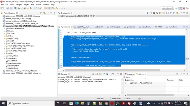
在下面的代码中,我可以看到使用逻辑分析器DIO8 MOSI从高到低的转换,但在SPI_init()中,代码挂起。

我已确定在 NTM88PinTable[]初始化Board_NTM88_MOSI时挂起的原因。 但问题是,如果我这样评论,我就不能将DIO8 MOSI线路的高电平切换为低电平。


-kel

  • 请注意,本文内容源自机器翻译,可能存在语法或其它翻译错误,仅供参考。如需获取准确内容,请参阅链接中的英语原文或自行翻译。

    我看到您在"for (i = 0;i < MAX_LOOP;I++)..."中的SPI_INIT后立即调用SPI_TRANSFER,但我认为调用顺序应该是这样

    SPI_init
    
    SPI_Params_init
    SPI_open
    
    //your loop to call
    SPI_transfer
    
    SPI_close

  • 请注意,本文内容源自机器翻译,可能存在语法或其它翻译错误,仅供参考。如需获取准确内容,请参阅链接中的英语原文或自行翻译。

    只是我在CC2640R2F块的结构图中的一项更正,PTA8就是DIO8。

    我需要使用DIO8双重用途作为GPIO从高转换到低,以通知NTM88 CC2640R2F将执行SPI传输。 之后,我需要通过调用SPI_OPEN()将DIO8配置为SPI MOSI。 问题是未创建句柄

    Yikai,我确实是按照这个顺序调用SPI C函数的。 我正在使用spimaster示例程序作为基础。 这是整个代码。

    /*
     *  ======== spimaster.c ========
     */
    #include <stddef.h>
    #include <stdint.h>
    #include <string.h>
    
    /* POSIX Header files */
    #include <pthread.h>
    #include <semaphore.h>
    #include <unistd.h>
    
    /* Driver Header files */
    /* Driver Header files */
    #include <ti/drivers/PIN.h>
    #include <ti/drivers/SPI.h>
    #include <ti/display/Display.h>
    
    /* Example/Board Header files */
    #include "Board.h"
    
    #define THREADSTACKSIZE (1024)
    
    #define SPI_MSG_LENGTH  (32) //NB_16BIT_XFERS*2 16 x 2 = 32
    #define MASTER_MSG      ("Hello from master, msg#: ")
    
    #define MAX_LOOP        (100)
    
    /*/!\ The same two macros below must be defined in the NTM88 project /!\ */
    #define ADDR_FIRST_DATA_BYTE    0xCF
    #define NB_DATA_BYTES           14
    
    /* Address to write in order to let the NTM88 CPU resume */
    #define ADDR_SPIOPS             0x38
    
    /* To read N data bytes, N+1 transfers are required.
     * In our implementation, one additional transfer is required
     * at the end to clear the SPIOPS register in the NTM88 memory.
     * So in total, we will perform N+2 transfers.
     */
    #define NB_16BIT_XFERS  (NB_DATA_BYTES + 2)


    //Local Function declaration
    static uint8_t u8SpiFillTxBuffer(void);
    static bool bSpiGetParity(uint8_t u8parityByte);
    static void vfnSpiFillBufferRead(uint16_t u16address, uint8_t *i);
    static void vfnSpiFillBufferWrite(uint16_t u16data, uint8_t *i);
    static void vfnSpiFillBufferCmd(uint16_t u16data, uint8_t *i);
    static uint8_t u8SpiGetStatus(uint16_t u16SpiRsp);
    static uint8_t u8SpiGetData(uint16_t u16SpiRsp);
    static uint8_t u8SpiStoreData(void);
    static void SPI_Init(void);
    
    //Local variables
    static Display_Handle display;
    
    static uint8_t gau8TxData[SPI_MSG_LENGTH] = {0};
    static uint8_t gau8RxData[SPI_MSG_LENGTH] = {0};
    
    SPI_Handle      masterSpi;
    SPI_Params      spiParams;
    SPI_Transaction transaction;
    
    typedef struct Send_Data {
        bool isDataToSend;
        uint8_t nb_bytes;
        uint8_t array_data[140];
    } t_Send_Data;
    
    t_Send_Data gSendData = {0, 0, {0}};
    
    /* Semaphore to block master until slave is ready for transfer */
    sem_t masterSem;
    
    /* Pin driver handles */
    static PIN_Handle NTM88PinHandle;
    
    /* Global memory storage for a PIN_Config table */
    static PIN_State NTM88PinState;
    
    /*
     * Application button pin configuration table:
     *   - Buttons interrupts are configured to trigger on falling edge.
     */
    PIN_Config NTM88PinTable[] = {
        Board_PIN_LED0 | PIN_GPIO_OUTPUT_EN | PIN_GPIO_HIGH | PIN_PUSHPULL | PIN_DRVSTR_MAX,     /* LED initially on */
        Board_PIN_LED1 | PIN_GPIO_OUTPUT_EN | PIN_GPIO_LOW | PIN_PUSHPULL | PIN_DRVSTR_MAX,      /* LED initially off */
        //Board_NTM88_SPI_CS | PIN_GPIO_OUTPUT_EN | PIN_GPIO_HIGH | PIN_PUSHPULL | PIN_DRVSTR_MIN, /* NTM88 chip select */
        //Board_NTM88_SCLK | PIN_INPUT_EN | PIN_PULLDOWN,                                          /* SPI clock */
        Board_NTM88_MOSI | PIN_GPIO_OUTPUT_EN | PIN_GPIO_HIGH | PIN_PUSHPULL | PIN_DRVSTR_MAX,   /* Configure MOSI first as output for NTM88 KBI input */
        //Board_NTM88_MISO | PIN_INPUT_EN | PIN_PULLDOWN,                                          /* SPI master MISO */
        Board_WAKE_UP | PIN_INPUT_EN | PIN_PULLUP | PIN_IRQ_POSEDGE | PIN_HYSTERESIS,            /* Wake Up pin driven by NTM88 */
        PIN_TERMINATE
    };
    
    /**********************************************************************************
     * Description: Fills the SPI transmission buffer with commands to read the sensor
     *              data and then let the NTM88 CPU resume.
     * Input: void
     * Output: void
     *********************************************************************************/
    static uint8_t u8SpiFillTxBuffer(void)
    {
        uint8_t i, buffer_index;
        uint16_t u16address;
    
        // We fill the buffer from the beginning
        buffer_index = 0;
    
        /***** READ commands to get the sensor data ******************/
        u16address = ADDR_FIRST_DATA_BYTE;
        for (i=0; i < NB_DATA_BYTES; i++)
        {
            vfnSpiFillBufferRead(u16address++, &buffer_index);
        }
    
        /***** WRITE commands to let the NTM88 resume operations *****/
        vfnSpiFillBufferWrite(ADDR_SPIOPS, &buffer_index);
        vfnSpiFillBufferWrite(0x00, &buffer_index);
    
        // Note that it would be necessary to perform an additional transfer to read the WRITE command status
        return buffer_index;
    }
    
    /**********************************************************************************
     * Description: Calculates and returns the parity of the byte passed as parameter
     * Input: u8parityByte, the byte of which we want to know the parity
     * Output: the parity
     *********************************************************************************/
    static bool bSpiGetParity(uint8_t u8parityByte)
    {
        uint8_t i=0;
        uint8_t u8count=0;
    
        for (i=0; i< 7 ; i++)
        {
            if (u8parityByte%2 == 1) u8count++; //increments count
            u8parityByte /= 2;
    
        }
        return (u8count%2 != 0);
    }
    
    /*****************************************************************************
     * Description: Adds a READ command to the SPI buffer and increments the buffer
     *              index
     * Input: uint16_t address, the address to read
     *        uint8_t* i, the pointer to the index in the buffer at which the command
     *        should be written
     * Output: void
     *****************************************************************************/
    static void vfnSpiFillBufferRead(uint16_t u16address, uint8_t *i)
    {
        vfnSpiFillBufferCmd(u16address, i);
    }
    
    /*****************************************************************************
     * Description: Adds a WRITE command to the SPI buffer and increments the buffer
     *              index
     * Input: uint16_t data, the data to write, which can be the address or the value
     *        to write
     *        uint8_t* i, the pointer to the index in the buffer at which the command
     *        should be written
     * Output: void
     *****************************************************************************/
    static void vfnSpiFillBufferWrite(uint16_t u16data, uint8_t *i)
    {
        u16data += (1<<13);
        vfnSpiFillBufferCmd(u16data, i);
    }
    
    /*****************************************************************************
     * Description: Formats the command, stores it in the SPI buffer and increments
     *              the buffer index
     * Input: uint16_t data, the data to write, which can be the address or the value
     *        to write
     *        uint8_t* i, the pointer to the index in the buffer at which the command
     *        should be written
     * Output: void
     *****************************************************************************/
    static void vfnSpiFillBufferCmd(uint16_t u16data, uint8_t *i)
    {
        /*
         * 16 bits format
         * OP Command for Write ---> 1 / for Read ---> 0
         * OP | A12 A11 A10 A9 A8 A7 A6 A5 A4 A3 A2 A1 A0 | P1 P0
         * x    Address    Address   Address  Address       Parity
         * P1 -> Parity for OP A12 A11 A10 A9 A8 A7
         * P2 -> Parity for A6  A5  A4  A3 A2 A1 A0
         */
    
        uint8_t u8parityByteMSB=0, u8parityByteLSB=0;
        bool bP0=0, bP1=0;
        uint8_t u8parityDuo=0;
        uint16_t u16CommandToTPMS=0;
    
        u8parityByteMSB = (uint8_t)(u16data / 128);
        u8parityByteLSB = (uint8_t)(u16data % 128);
    
        bP1 = bSpiGetParity(u8parityByteMSB);
        bP0 = bSpiGetParity(u8parityByteLSB);
    
        // Combining P1 and P0
        u8parityDuo = 2*bP1 + bP0;
    
        u16CommandToTPMS = (uint16_t)(u16data<<2) + u8parityDuo;
        gau8TxData[(*i)++] = u16CommandToTPMS & 0xFF; // LSByte first
        gau8TxData[(*i)++] = u16CommandToTPMS / 256; // MSByte second
    
        return;
    }
    
    /**********************************************************************************
     * Description: Extracts the 8-bit status from the 16-bit response
     * Input: void
     * Output: void
     *********************************************************************************/
    static uint8_t u8SpiGetStatus(uint16_t u16SpiRsp)
    {
        return (u16SpiRsp>>10)& 0x1F;
    }
    
    /**********************************************************************************
     * Description: Extracts the 8-bit data from the 16-bit response
     * Input: void
     * Output: void
     *********************************************************************************/
    static uint8_t u8SpiGetData(uint16_t u16SpiRsp)
    {
        return (u16SpiRsp>>2)& 0xFF;
    }
    
    /**********************************************************************************
     * Description: Stores the data read via SPI
     * Input: void
     * Output: void
     *********************************************************************************/
    static uint8_t u8SpiStoreData(void)
    {
        uint8_t i;
        uint8_t u8offset_read_data;
        uint16_t u16spi_response;
        uint8_t u8read_status = 0;
    
        /* We discard the response of the first 16-bit xfer since it contains no information,
           so we discard indexes 0 and 1 */
        u8offset_read_data = 2;
    
        for (i=0; i<NB_DATA_BYTES; i++)
        {
            // First, re-assemble the 16-bit response
            u16spi_response = (uint16_t)(gau8RxData[2*i+1+u8offset_read_data]); // MSByte
            u16spi_response <<= 8;
            u16spi_response &= 0xFF00;
            u16spi_response |= gau8RxData[2*i+u8offset_read_data]; // LSByte
            // Then extract the data and status from it
            gSendData.array_data[i] = u8SpiGetData(u16spi_response);
            u8read_status |= u8SpiGetStatus(u16spi_response);
        }
    
        gSendData.nb_bytes = NB_DATA_BYTES;
    
        return u8read_status;
    }
    
    
    /*
     *  ======== slaveReadyFxn ========
     *  Callback function for the GPIO interrupt on Board_SPI_SLAVE_READY.
     */
    void slaveReadyFxn(PIN_Handle handle, PIN_Id pinId)
    {
        sem_post(&masterSem);
    }
    
    static void SPI_Init(void)
    {
        /* Open SPI as master (default) */
        SPI_Params_init(&spiParams);
        spiParams.frameFormat = SPI_POL0_PHA0; /*!< SPI mode Polarity 0 Phase 0 */
        spiParams.bitRate = 10000000;
        spiParams.dataSize = 16;
        masterSpi = SPI_open(Board_SPI_MASTER, &spiParams);
        if (masterSpi == NULL) {
            Display_printf(display, 0, 0, "Error initializing master SPI\n");
            while (1);
        }
        else {
            Display_printf(display, 0, 0, "Master SPI initialized\n");
        }
    }
    
    /*
     *  ======== masterThread ========
     *  Master SPI sends a message to slave while simultaneously receiving a
     *  message from the slave.
     */
    void *masterThread(void *arg0)
    {
    
        uint32_t        i;
        bool            transferOK;
        int32_t         status;
    
        NTM88PinHandle = PIN_open(&NTM88PinState, NTM88PinTable);
    
        if(!NTM88PinHandle)
        {
           /* Error initializing button pins */
           while(1);
        }
    
        /* Setup callback for button pins */
        if (PIN_registerIntCb(NTM88PinHandle, &slaveReadyFxn) != 0) {
            /* Error registering button callback function */
            while(1);
        }
    
        status = sem_init(&masterSem, 0, 0);
        if (status != 0) {
            Display_printf(display, 0, 0, "Error creating masterSem\n");
            while(1);
        }


        uint8_t u8xfer_nb_bytes = 0;
    
        for (i = 0; i < MAX_LOOP; i++)
        {
            PIN_setOutputValue(NTM88PinHandle, Board_NTM88_MOSI, 1);
            while(PIN_getInputValue(Board_WAKE_UP) == 0) {} // Wait for NTM88 Slave Ready to be high
    
    
            PIN_setOutputValue(NTM88PinHandle, Board_NTM88_MOSI, 0); //Set NTM88 KBI pin low
            /*
             * Wait until slave is ready for transfer; slave will pull
             * Board_SPI_SLAVE_READY low.
             */
    
            sem_wait(&masterSem);
    
            PIN_setConfig(NTM88PinHandle, PIN_INPUT_EN, CC2640R2_LAUNCHXL_SPI0_MOSI | PIN_INPUT_EN | PIN_PULLDOWN);
    
            SPI_Init();  // not able to SPI_open hang here ! ! !
    
            u8xfer_nb_bytes = u8SpiFillTxBuffer();
    
            /* Initialize master SPI transaction structure */
            transaction.count = u8xfer_nb_bytes;
            transaction.txBuf = (void *) gau8TxData;
            transaction.rxBuf = (void *) gau8RxData;
    
            /* Toggle user LED, indicating a SPI transfer is in progress */
            PIN_setOutputValue(NTM88PinHandle, Board_PIN_LED1, !PIN_getOutputValue(Board_PIN_LED1));
    
            /* Perform SPI transfer */
            transferOK = SPI_transfer(masterSpi, &transaction);
            if (transferOK) {
                Display_printf(display, 0, 0, "Master received: ");
            }
            else {
                Display_printf(display, 0, 0, "Unsuccessful master SPI transfer");
            }
    
            SPI_close(masterSpi);
    
            PIN_setConfig(NTM88PinHandle, PIN_GPIO_OUTPUT_EN, CC2640R2_LAUNCHXL_SPI0_MOSI | PIN_GPIO_OUTPUT_EN | PIN_GPIO_HIGH | PIN_PUSHPULL | PIN_DRVSTR_MAX);
    
            u8SpiStoreData();
        }
    
    
        Display_printf(display, 0, 0, "\nDone");
    
        return (NULL);
    }
    
    /*
     *  ======== mainThread ========
     */
    void *mainThread(void *arg0)
    {
        pthread_t           thread0;
        pthread_attr_t      attrs;
        struct sched_param  priParam;
        int                 retc;
        int                 detachState;
    
        /* Call driver init functions. */
        Display_init();
        //GPIO_init();
        SPI_init();
    
        /* Configure the LED pins */
        //GPIO_setConfig(Board_GPIO_LED0, GPIO_CFG_OUT_STD | GPIO_CFG_OUT_LOW);
        //GPIO_setConfig(Board_GPIO_LED1, GPIO_CFG_OUT_STD | GPIO_CFG_OUT_LOW);
    
        /* Open the display for output */
        display = Display_open(Display_Type_UART, NULL);
        if (display == NULL) {
            /* Failed to open display driver */
            while (1);
        }
    
        /* Turn on user LED */
        //GPIO_write(Board_GPIO_LED0, Board_GPIO_LED_ON);
    
        Display_printf(display, 0, 0, "Starting the CC2640R2F SPI master");
    
        /* Create application threads */
        pthread_attr_init(&attrs);
    
        detachState = PTHREAD_CREATE_DETACHED;
        /* Set priority and stack size attributes */
        retc = pthread_attr_setdetachstate(&attrs, detachState);
        if (retc != 0) {
            /* pthread_attr_setdetachstate() failed */
            while (1);
        }
    
        retc |= pthread_attr_setstacksize(&attrs, THREADSTACKSIZE);
        if (retc != 0) {
            /* pthread_attr_setstacksize() failed */
            while (1);
        }
    
        /* Create master thread */
        priParam.sched_priority = 1;
        pthread_attr_setschedparam(&attrs, &priParam);
    
        retc = pthread_create(&thread0, &attrs, masterThread, NULL);
        if (retc != 0) {
            /* pthread_create() failed */
            while (1);
        }
    
        return (NULL);
    }

    -kel

  • 请注意,本文内容源自机器翻译,可能存在语法或其它翻译错误,仅供参考。如需获取准确内容,请参阅链接中的英语原文或自行翻译。

    您是否打算在While循环以及SPI_Init和SPI_transfer之间将DIO8作为GPI和MOSI进行操作?

  • 请注意,本文内容源自机器翻译,可能存在语法或其它翻译错误,仅供参考。如需获取准确内容,请参阅链接中的英语原文或自行翻译。
    2640 able-open-open-spi/4068742#4068spi_4068742f]在406.8742万在SPI_和4068SPI_和MOSI_I406.8742万MOSI_I之间进行循环传输时,引用吗?

    这就是我最初所做的。 然后我将其更改为下面的内容。 调用SPI_open()时未创建句柄。

    pin_open()

    PIN_registerIntCb()

    PIN_setOutputValue (NTM88PinHandle,Board_NTM88_MOSI,1);
    while (PIN_getInputValue (Board_WAKE_UP)== 0){}//等待NTM88 Slave Ready高


    PIN_setOutputValue (NTM88PinHandle,Board_NTM88_MOSI,0);  

    PIN_setConfig (NTM88PinHandle,PIN_INPUT_EN,CC2640R2_LAUNCHXL_SPI0_MOSI | PIN_INPUT_EN | PIN_Pulldown);

    SPI_init();

    SPI_Params_init()

    SPI_open()

    SPI_TRANSFOR()

    SPI_CLOSE (关闭)

    PIN_setConfig (NTM88PinHandle,PIN_GPIO输出_EN,CC2640R2_LAUNCHXL_SPI0_MOSI | PIN_GPIO输出_EN | PIN_GPIO高| PIN_PushPull | PIN_DRVSTR_MAX);

    /*
     *  ======== spimaster.c ========
     */
    #include <stddef.h>
    #include <stdint.h>
    #include <string.h>
    
    /* POSIX Header files */
    #include <pthread.h>
    #include <semaphore.h>
    #include <unistd.h>
    
    /* Driver Header files */
    /* Driver Header files */
    #include <ti/drivers/PIN.h>
    #include <ti/drivers/SPI.h>
    #include <ti/display/Display.h>
    
    /* Example/Board Header files */
    #include "Board.h"
    
    #define THREADSTACKSIZE (1024)
    
    #define SPI_MSG_LENGTH  (32) //NB_16BIT_XFERS*2 16 x 2 = 32
    #define MASTER_MSG      ("Hello from master, msg#: ")
    
    #define MAX_LOOP        (100)
    
    /*/!\ The same two macros below must be defined in the NTM88 project /!\ */
    #define ADDR_FIRST_DATA_BYTE    0xCF
    #define NB_DATA_BYTES           14
    
    /* Address to write in order to let the NTM88 CPU resume */
    #define ADDR_SPIOPS             0x38
    
    /* To read N data bytes, N+1 transfers are required.
     * In our implementation, one additional transfer is required
     * at the end to clear the SPIOPS register in the NTM88 memory.
     * So in total, we will perform N+2 transfers.
     */
    #define NB_16BIT_XFERS  (NB_DATA_BYTES + 2)


    //Local Function declaration
    static uint8_t u8SpiFillTxBuffer(void);
    static bool bSpiGetParity(uint8_t u8parityByte);
    static void vfnSpiFillBufferRead(uint16_t u16address, uint8_t *i);
    static void vfnSpiFillBufferWrite(uint16_t u16data, uint8_t *i);
    static void vfnSpiFillBufferCmd(uint16_t u16data, uint8_t *i);
    static uint8_t u8SpiGetStatus(uint16_t u16SpiRsp);
    static uint8_t u8SpiGetData(uint16_t u16SpiRsp);
    static uint8_t u8SpiStoreData(void);
    static void SPI_Init(void);
    
    //Local variables
    static Display_Handle display;
    
    static uint8_t gau8TxData[SPI_MSG_LENGTH] = {0};
    static uint8_t gau8RxData[SPI_MSG_LENGTH] = {0};
    
    SPI_Handle      masterSpi;
    SPI_Params      spiParams;
    SPI_Transaction transaction;
    
    typedef struct Send_Data {
        bool isDataToSend;
        uint8_t nb_bytes;
        uint8_t array_data[140];
    } t_Send_Data;
    
    t_Send_Data gSendData = {0, 0, {0}};
    
    /* Semaphore to block master until slave is ready for transfer */
    sem_t masterSem;
    
    /* Pin driver handles */
    static PIN_Handle NTM88PinHandle;
    
    /* Global memory storage for a PIN_Config table */
    static PIN_State NTM88PinState;
    
    /*
     * Application button pin configuration table:
     *   - Buttons interrupts are configured to trigger on falling edge.
     */
    PIN_Config NTM88PinTable[] = {
        Board_PIN_LED0 | PIN_GPIO_OUTPUT_EN | PIN_GPIO_HIGH | PIN_PUSHPULL | PIN_DRVSTR_MAX,     /* LED initially on */
        Board_PIN_LED1 | PIN_GPIO_OUTPUT_EN | PIN_GPIO_LOW | PIN_PUSHPULL | PIN_DRVSTR_MAX,      /* LED initially off */
        //Board_NTM88_SPI_CS | PIN_GPIO_OUTPUT_EN | PIN_GPIO_HIGH | PIN_PUSHPULL | PIN_DRVSTR_MIN, /* NTM88 chip select */
        //Board_NTM88_SCLK | PIN_INPUT_EN | PIN_PULLDOWN,                                          /* SPI clock */
        Board_NTM88_MOSI | PIN_GPIO_OUTPUT_EN | PIN_GPIO_HIGH | PIN_PUSHPULL | PIN_DRVSTR_MAX,   /* Configure MOSI first as output for NTM88 KBI input */
        //Board_NTM88_MISO | PIN_INPUT_EN | PIN_PULLDOWN,                                          /* SPI master MISO */
        Board_WAKE_UP | PIN_INPUT_EN | PIN_PULLUP | PIN_IRQ_POSEDGE | PIN_HYSTERESIS,            /* Wake Up pin driven by NTM88 */
        PIN_TERMINATE
    };
    
    /**********************************************************************************
     * Description: Fills the SPI transmission buffer with commands to read the sensor
     *              data and then let the NTM88 CPU resume.
     * Input: void
     * Output: void
     *********************************************************************************/
    static uint8_t u8SpiFillTxBuffer(void)
    {
        uint8_t i, buffer_index;
        uint16_t u16address;
    
        // We fill the buffer from the beginning
        buffer_index = 0;
    
        /***** READ commands to get the sensor data ******************/
        u16address = ADDR_FIRST_DATA_BYTE;
        for (i=0; i < NB_DATA_BYTES; i++)
        {
            vfnSpiFillBufferRead(u16address++, &buffer_index);
        }
    
        /***** WRITE commands to let the NTM88 resume operations *****/
        vfnSpiFillBufferWrite(ADDR_SPIOPS, &buffer_index);
        vfnSpiFillBufferWrite(0x00, &buffer_index);
    
        // Note that it would be necessary to perform an additional transfer to read the WRITE command status
        return buffer_index;
    }
    
    /**********************************************************************************
     * Description: Calculates and returns the parity of the byte passed as parameter
     * Input: u8parityByte, the byte of which we want to know the parity
     * Output: the parity
     *********************************************************************************/
    static bool bSpiGetParity(uint8_t u8parityByte)
    {
        uint8_t i=0;
        uint8_t u8count=0;
    
        for (i=0; i< 7 ; i++)
        {
            if (u8parityByte%2 == 1) u8count++; //increments count
            u8parityByte /= 2;
    
        }
        return (u8count%2 != 0);
    }
    
    /*****************************************************************************
     * Description: Adds a READ command to the SPI buffer and increments the buffer
     *              index
     * Input: uint16_t address, the address to read
     *        uint8_t* i, the pointer to the index in the buffer at which the command
     *        should be written
     * Output: void
     *****************************************************************************/
    static void vfnSpiFillBufferRead(uint16_t u16address, uint8_t *i)
    {
        vfnSpiFillBufferCmd(u16address, i);
    }
    
    /*****************************************************************************
     * Description: Adds a WRITE command to the SPI buffer and increments the buffer
     *              index
     * Input: uint16_t data, the data to write, which can be the address or the value
     *        to write
     *        uint8_t* i, the pointer to the index in the buffer at which the command
     *        should be written
     * Output: void
     *****************************************************************************/
    static void vfnSpiFillBufferWrite(uint16_t u16data, uint8_t *i)
    {
        u16data += (1<<13);
        vfnSpiFillBufferCmd(u16data, i);
    }
    
    /*****************************************************************************
     * Description: Formats the command, stores it in the SPI buffer and increments
     *              the buffer index
     * Input: uint16_t data, the data to write, which can be the address or the value
     *        to write
     *        uint8_t* i, the pointer to the index in the buffer at which the command
     *        should be written
     * Output: void
     *****************************************************************************/
    static void vfnSpiFillBufferCmd(uint16_t u16data, uint8_t *i)
    {
        /*
         * 16 bits format
         * OP Command for Write ---> 1 / for Read ---> 0
         * OP | A12 A11 A10 A9 A8 A7 A6 A5 A4 A3 A2 A1 A0 | P1 P0
         * x    Address    Address   Address  Address       Parity
         * P1 -> Parity for OP A12 A11 A10 A9 A8 A7
         * P2 -> Parity for A6  A5  A4  A3 A2 A1 A0
         */
    
        uint8_t u8parityByteMSB=0, u8parityByteLSB=0;
        bool bP0=0, bP1=0;
        uint8_t u8parityDuo=0;
        uint16_t u16CommandToTPMS=0;
    
        u8parityByteMSB = (uint8_t)(u16data / 128);
        u8parityByteLSB = (uint8_t)(u16data % 128);
    
        bP1 = bSpiGetParity(u8parityByteMSB);
        bP0 = bSpiGetParity(u8parityByteLSB);
    
        // Combining P1 and P0
        u8parityDuo = 2*bP1 + bP0;
    
        u16CommandToTPMS = (uint16_t)(u16data<<2) + u8parityDuo;
        gau8TxData[(*i)++] = u16CommandToTPMS & 0xFF; // LSByte first
        gau8TxData[(*i)++] = u16CommandToTPMS / 256; // MSByte second
    
        return;
    }
    
    /**********************************************************************************
     * Description: Extracts the 8-bit status from the 16-bit response
     * Input: void
     * Output: void
     *********************************************************************************/
    static uint8_t u8SpiGetStatus(uint16_t u16SpiRsp)
    {
        return (u16SpiRsp>>10)& 0x1F;
    }
    
    /**********************************************************************************
     * Description: Extracts the 8-bit data from the 16-bit response
     * Input: void
     * Output: void
     *********************************************************************************/
    static uint8_t u8SpiGetData(uint16_t u16SpiRsp)
    {
        return (u16SpiRsp>>2)& 0xFF;
    }
    
    /**********************************************************************************
     * Description: Stores the data read via SPI
     * Input: void
     * Output: void
     *********************************************************************************/
    static uint8_t u8SpiStoreData(void)
    {
        uint8_t i;
        uint8_t u8offset_read_data;
        uint16_t u16spi_response;
        uint8_t u8read_status = 0;
    
        /* We discard the response of the first 16-bit xfer since it contains no information,
           so we discard indexes 0 and 1 */
        u8offset_read_data = 2;
    
        for (i=0; i<NB_DATA_BYTES; i++)
        {
            // First, re-assemble the 16-bit response
            u16spi_response = (uint16_t)(gau8RxData[2*i+1+u8offset_read_data]); // MSByte
            u16spi_response <<= 8;
            u16spi_response &= 0xFF00;
            u16spi_response |= gau8RxData[2*i+u8offset_read_data]; // LSByte
            // Then extract the data and status from it
            gSendData.array_data[i] = u8SpiGetData(u16spi_response);
            u8read_status |= u8SpiGetStatus(u16spi_response);
        }
    
        gSendData.nb_bytes = NB_DATA_BYTES;
    
        return u8read_status;
    }
    
    
    /*
     *  ======== slaveReadyFxn ========
     *  Callback function for the GPIO interrupt on Board_SPI_SLAVE_READY.
     */
    void slaveReadyFxn(PIN_Handle handle, PIN_Id pinId)
    {
        sem_post(&masterSem);
    }
    
    static void SPI_Init(void)
    {
        SPI_init();
        /* Open SPI as master (default) */
        SPI_Params_init(&spiParams);
        spiParams.frameFormat = SPI_POL0_PHA0; /*!< SPI mode Polarity 0 Phase 0 */
        spiParams.bitRate = 10000000;
        spiParams.dataSize = 16;
        masterSpi = SPI_open(Board_SPI_MASTER, &spiParams);
        if (masterSpi == NULL) {
            Display_printf(display, 0, 0, "Error initializing master SPI\n");
            while (1);
        }
        else {
            Display_printf(display, 0, 0, "Master SPI initialized\n");
        }
    }
    
    /*
     *  ======== masterThread ========
     *  Master SPI sends a message to slave while simultaneously receiving a
     *  message from the slave.
     */
    void *masterThread(void *arg0)
    {
    
        uint32_t        i;
        bool            transferOK;
        int32_t         status;
    
        NTM88PinHandle = PIN_open(&NTM88PinState, NTM88PinTable);
    
        if(!NTM88PinHandle)
        {
           /* Error initializing button pins */
           while(1);
        }
    
        /* Setup callback for button pins */
        if (PIN_registerIntCb(NTM88PinHandle, &slaveReadyFxn) != 0) {
            /* Error registering button callback function */
            while(1);
        }
    
        status = sem_init(&masterSem, 0, 0);
        if (status != 0) {
            Display_printf(display, 0, 0, "Error creating masterSem\n");
            while(1);
        }


        uint8_t u8xfer_nb_bytes = 0;
    
        for (i = 0; i < MAX_LOOP; i++)
        {
            PIN_setOutputValue(NTM88PinHandle, Board_NTM88_MOSI, 1);
            while(PIN_getInputValue(Board_WAKE_UP) == 0) {} // Wait for NTM88 Slave Ready to be high
    
    
            PIN_setOutputValue(NTM88PinHandle, Board_NTM88_MOSI, 0); //Set NTM88 KBI pin low
            /*
             * Wait until slave is ready for transfer; slave will pull
             * Board_SPI_SLAVE_READY low.
             */
    
            sem_wait(&masterSem);
    
            PIN_setConfig(NTM88PinHandle, PIN_INPUT_EN, CC2640R2_LAUNCHXL_SPI0_MOSI | PIN_INPUT_EN | PIN_PULLDOWN);
    
            SPI_Init();  // not able to SPI_open hang here ! ! !
    
            u8xfer_nb_bytes = u8SpiFillTxBuffer();
    
            /* Initialize master SPI transaction structure */
            transaction.count = u8xfer_nb_bytes;
            transaction.txBuf = (void *) gau8TxData;
            transaction.rxBuf = (void *) gau8RxData;
    
            /* Toggle user LED, indicating a SPI transfer is in progress */
            PIN_setOutputValue(NTM88PinHandle, Board_PIN_LED1, !PIN_getOutputValue(Board_PIN_LED1));
    
            /* Perform SPI transfer */
            transferOK = SPI_transfer(masterSpi, &transaction);
            if (transferOK) {
                Display_printf(display, 0, 0, "Master received: ");
            }
            else {
                Display_printf(display, 0, 0, "Unsuccessful master SPI transfer");
            }
    
            SPI_close(masterSpi);
    
            PIN_setConfig(NTM88PinHandle, PIN_GPIO_OUTPUT_EN, CC2640R2_LAUNCHXL_SPI0_MOSI | PIN_GPIO_OUTPUT_EN | PIN_GPIO_HIGH | PIN_PUSHPULL | PIN_DRVSTR_MAX);
    
            u8SpiStoreData();
        }
    
    
        Display_printf(display, 0, 0, "\nDone");
    
        return (NULL);
    }
    
    /*
     *  ======== mainThread ========
     */
    void *mainThread(void *arg0)
    {
        pthread_t           thread0;
        pthread_attr_t      attrs;
        struct sched_param  priParam;
        int                 retc;
        int                 detachState;
    
        /* Call driver init functions. */
        Display_init();
    
        /* Open the display for output */
        display = Display_open(Display_Type_UART, NULL);
        if (display == NULL) {
            /* Failed to open display driver */
            while (1);
        }
    
        /* Turn on user LED */
        //GPIO_write(Board_GPIO_LED0, Board_GPIO_LED_ON);
    
        Display_printf(display, 0, 0, "Starting the CC2640R2F SPI master");
    
        /* Create application threads */
        pthread_attr_init(&attrs);
    
        detachState = PTHREAD_CREATE_DETACHED;
        /* Set priority and stack size attributes */
        retc = pthread_attr_setdetachstate(&attrs, detachState);
        if (retc != 0) {
            /* pthread_attr_setdetachstate() failed */
            while (1);
        }
    
        retc |= pthread_attr_setstacksize(&attrs, THREADSTACKSIZE);
        if (retc != 0) {
            /* pthread_attr_setstacksize() failed */
            while (1);
        }
    
        /* Create master thread */
        priParam.sched_priority = 1;
        pthread_attr_setschedparam(&attrs, &priParam);
    
        retc = pthread_create(&thread0, &attrs, masterThread, NULL);
        if (retc != 0) {
            /* pthread_create() failed */
            while (1);
        }
    
        return (NULL);
    }

    -kel

  • 请注意,本文内容源自机器翻译,可能存在语法或其它翻译错误,仅供参考。如需获取准确内容,请参阅链接中的英语原文或自行翻译。

    我只是解决问题。

    我必须首先调用Pin_close(),然后调用SPI_init()。 但是,这 是一种令人厌烦的解决方案。 无论如何,只要我能够继续这样做。

    PIN_CLOSE (NTM88PinHandle);

    SPI_Init();//不能SPI_OPEN在此处挂起! ! !

    -kel

  • 请注意,本文内容源自机器翻译,可能存在语法或其它翻译错误,仅供参考。如需获取准确内容,请参阅链接中的英语原文或自行翻译。

    这是我怀疑的,很好地知道你自己弄清楚了。