Other Parts Discussed in Thread: CC2642R, CC2640R2F
请注意,本文内容源自机器翻译,可能存在语法或其它翻译错误,仅供参考。如需获取准确内容,请参阅链接中的英语原文或自行翻译。
器件型号:CC2640R2F 主题中讨论的其他器件:CC2642R、
大家好、
以下是客户提出的问题、可能需要您的帮助:
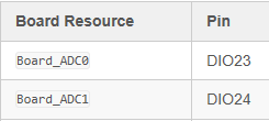
从电路板资源的角度来看、ADC0在 DIO23上输入、ADC1在 DIO24上输入:
Board_init()在进入 main()后首先执行;
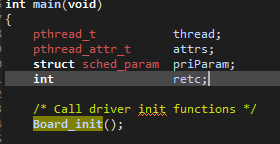
Board_init()也调用 CC2640R2_LAUNCHXL_initGeneral();
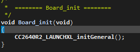
在 CC2640R2_LAUNCHXL_initGeneral()中;执行 Power_init();然后执行 PIN_init();
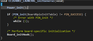
1) Power_init()做什么?初始化电源相关资源?但似乎再次处理时钟。 如果应用不涉及电源管理、是否可以在不修改内容的情况下直接调用它?
 *  ======== Power_init ========
 */
int_fast16_t Power_init()
{
    ClockP_Params clockParams;
    uint32_t ccfgLfClkSrc;
    uint32_t timeout;

    /* if this function has already been called, just return */
    if (PowerCC26XX_module.initialized) {
        return (Power_SOK);
    }

#if defined(DeviceFamily_CC26X0R2)
    /* check to see if the JTAG_PD is on, meaning the emulator was attached during boot and */
    /* that the user is in an active debug session */
    PowerCC26XX_module.emulatorAttached = (HWREG(AON_WUC_BASE + AON_WUC_O_PWRSTAT) & AON_WUC_PWRSTAT_JTAG_PD_ON) == AON_WUC_PWRSTAT_JTAG_PD_ON;
#endif

    /* set module state field 'initialized' to true */
    PowerCC26XX_module.initialized = true;

    /* set the module state enablePolicy field */
    PowerCC26XX_module.enablePolicy = PowerCC26XX_config.enablePolicy;

    /* copy the Power policy function to module state */
    PowerCC26XX_module.policyFxn = PowerCC26XX_config.policyFxn;

    /* construct the Clock object for scheduling of wakeups */
    /* initiated and started by the power policy */
    ClockP_Params_init(&clockParams);
    clockParams.period = 0;
    clockParams.startFlag = false;
    clockParams.arg = 0;
    ClockP_construct(&PowerCC26XX_module.clockObj, &emptyClockFunc,
        0, &clockParams);

    /* construct the Clock object for XOSC_HF switching */
    /* initiated and started by Power module when activating XOSC_HF */
    ClockP_construct(&PowerCC26XX_module.xoscClockObj, &switchXOSCHFclockFunc,
        0, &clockParams);

    /* construct the Clock object for disabling LF clock quailifiers */
    /* one shot, auto start, first expires at 100 msec */
    ClockP_construct(&PowerCC26XX_module.lfClockObj, &lfClockReadyCallback,
        0, &clockParams);

    (*(PowerCC26XX_config.calibrateFxn))(PowerCC26XX_SETUP_CALIBRATE);

    DRIVERLIB_ASSERT_CURR_RELEASE();
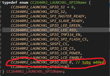
2) PIN_init()中的 BoardGpioInitTable 没有提到 ADC0 (DIO23)和 ADC1 (DIO24),它们的初始化代码在哪里?
const PIN_Config BoardGpioInitTable[] = {

    CC2640R2_LAUNCHXL_PIN_RLED | PIN_GPIO_OUTPUT_EN | PIN_GPIO_LOW | PIN_PUSHPULL | PIN_DRVSTR_MAX,       /* LED initially off */
    CC2640R2_LAUNCHXL_PIN_GLED | PIN_GPIO_OUTPUT_EN | PIN_GPIO_LOW | PIN_PUSHPULL | PIN_DRVSTR_MAX,       /* LED initially off */
    CC2640R2_LAUNCHXL_PIN_BTN1 | PIN_INPUT_EN | PIN_PULLUP | PIN_IRQ_BOTHEDGES | PIN_HYSTERESIS,          /* Button is active low */
    CC2640R2_LAUNCHXL_PIN_BTN2 | PIN_INPUT_EN | PIN_PULLUP | PIN_IRQ_BOTHEDGES | PIN_HYSTERESIS,          /* Button is active low */
    CC2640R2_LAUNCHXL_SPI_FLASH_CS | PIN_GPIO_OUTPUT_EN | PIN_GPIO_HIGH | PIN_PUSHPULL | PIN_DRVSTR_MIN,  /* External flash chip select */
    CC2640R2_LAUNCHXL_UART_RX | PIN_INPUT_EN | PIN_PULLDOWN,                                              /* UART RX via debugger back channel */
    CC2640R2_LAUNCHXL_UART_TX | PIN_GPIO_OUTPUT_EN | PIN_GPIO_LOW | PIN_PUSHPULL,                         /* UART TX via debugger back channel */
    CC2640R2_LAUNCHXL_SPI0_MOSI | PIN_INPUT_EN | PIN_PULLDOWN,                                            /* SPI master out - slave in */
    CC2640R2_LAUNCHXL_SPI0_MISO | PIN_INPUT_EN | PIN_PULLDOWN,                                            /* SPI master in - slave out */
    CC2640R2_LAUNCHXL_SPI0_CLK | PIN_INPUT_EN | PIN_PULLDOWN,                                             /* SPI clock */

    PIN_TERMINATE
};
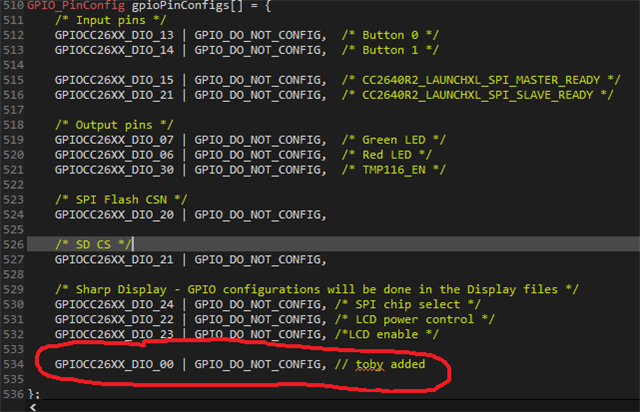
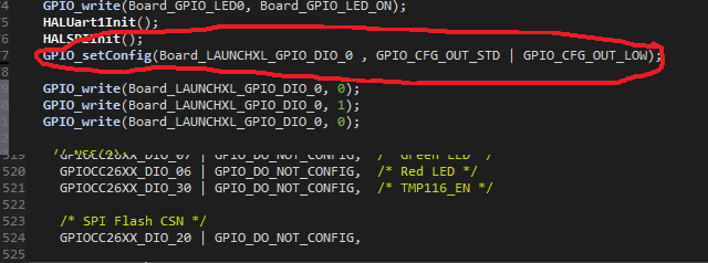
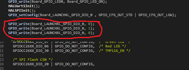
3) 3)此处定义 了 SPI0使用的引脚:
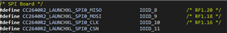
这些引脚在此处初始化:

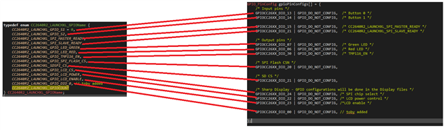
但 IOID_8~IOID_11如何映射到 SPI0外设?
4) 4) 相同的 PIN 可以映射多个功能、例如数字 IO、模拟输入等。是否有任何有关如何映射的文档?
您可以帮助检查此案例吗? 谢谢。
此致、
樱桃