This thread has been locked.

If you have a related question, please click the "Ask a related question" button in the top right corner. The newly created question will be automatically linked to this question.

[参考译文] LAUNCHXL-CC2640R2:附带 Raspberry Pi 的 SPI 4.

Guru**** 2337880 points
Other Parts Discussed in Thread: LAUNCHXL-CC2640R2
请注意,本文内容源自机器翻译,可能存在语法或其它翻译错误,仅供参考。如需获取准确内容,请参阅链接中的英语原文或自行翻译。

https://e2e.ti.com/support/wireless-connectivity/bluetooth-group/bluetooth/f/bluetooth-forum/1447894/launchxl-cc2640r2-spi-with-raspberry-pi-4

器件型号:LAUNCHXL-CC2640R2

工具与软件:

我正在尝试通过 SPI 在 Raspberry Pi 4和 LaunchXL-CC2640R2之间进行通信。  我已经看了 cc2640r2 SDK 驱动程序部分中的 spiMaster 和 spiSlave 示例、这些示例正常运行。  然后、我使用 Raspberry Pi 上的 WiringPi 编写了一个 c 程序、并将其编码成与 spiMaster.c 中的 masterThread 函数完全相同  我打印了值、两个电路板正在通信、但我只是从 cc2640r2收到垃圾、并且运行从程序的 cc2640r2报告未收到充当主系统的 RaspberryPi 提供的任何数据。  
因此、我连接了一个逻辑分析仪并验证了是否存在 Raspberry Pi 上 MOSI 引脚上的字符串"Hello from master、msg#:"。  因此、我不清楚 cc2640r2为何不会报告任何内容。  然后、我看到、Raspberry PI 的 MISO 线路上也有数据返回。  当我转换 ASCII 字母时、虽然它只是垃圾。  我认为这可能是同步问题或位速问题。  或者、可能是电压问题吗?  Pi 上的程序是用于指令   spiMaster.c 中的 masterThread 函数中编码的内容的指令  我正在使用信标以及同样的 SPI_MASTER_READY 和 SPI_SLAVE_READY 引脚。  所有的沟通似乎都很好。 只是数据混乱。  我们非常感谢您提出任何想法并帮助我摆脱困境。   

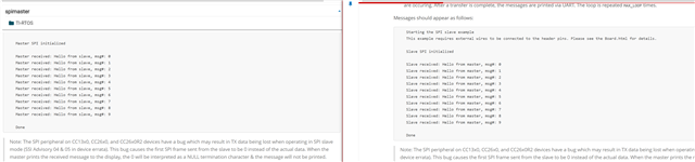
以下是 spiMaster 示例供参考:

dev.ti.com/.../node

这里是 spiSlave 示例:  

https://dev.ti.com/tirex/explore/node?devtools=LAUNCHXL-CC2640R2&node=A__AFb4htsUfPuLkydHKdlbtQ__com.ti.SIMPLELINK_CC2640R2_SDK__krol.2c__LATEST&placeholder=true

以下是我的代码  

#include <unistd.h>
#include <pthread.h>
#include <time.h>
#include <stdio.h>
#include <stdlib.h>
#include <string.h>
#include <errno.h>
#include "lvgl/lvgl.h"
#include "wiringPi.h"
#include "wiringPiSPI.h"
#include <semaphore.h>

#define	SPI_CHAN		0
// #define SPI_SPEED       500000
#define SPI_SPEED   4000000
#define SPI_MASTER_READY 2
#define SPI_SLAVE_READY 3
#define MASTER_MESSAGE ("Hello from master, msg#: ")
// #define MASTER_MESSAGE 0x48
#define SPI_MSG_LENGTH 30
#define MAX_LOOP 10

/* Global Variables */
int fd;
int readValue;
bool transferComplete;
// unsigned char masterTxBuffer[SPI_MSG_LENGTH];
unsigned char* masterTxBuffer;
sem_t masterSem;

/* Functions */
void lv_linux_run_loop(void);
void search_handler(lv_event_t *event);
void setUpSPI(void);

int main(void) {
    lv_init();
    const char *device = getenv("LV_LINUX_FBDEV_DEVICE") ? : "/dev/fb0";
    lv_display_t * display = lv_linux_fbdev_create();
    
    lv_linux_fbdev_set_file(display, device);

    lv_obj_set_style_bg_color(lv_screen_active(), lv_color_hex(0x000000), LV_PART_MAIN);
   
    /* Touchpad Monitor  
       Need to add code to search /proc/bus/input/devices for name of event Name="10-0038 generic ft5x06 (79)"
       for(int i =0; i < ) 
    */ 
    lv_indev_t *touch = lv_evdev_create(LV_INDEV_TYPE_POINTER, "/dev/input/event0");
    lv_indev_set_display(touch, display);
    

    /* LAYOUT */

    lv_obj_t* label;
    lv_obj_t *searchButton = lv_button_create(lv_screen_active());
    lv_obj_align(searchButton, LV_ALIGN_CENTER, 0, 0);
    lv_obj_set_size(searchButton, lv_pct(20), lv_pct(10));
    lv_obj_add_event_cb(searchButton, search_handler, LV_EVENT_ALL, NULL);
    lv_obj_remove_flag(searchButton, LV_OBJ_FLAG_PRESS_LOCK);
    lv_obj_add_flag(searchButton, LV_OBJ_FLAG_CLICKABLE);
    label = lv_label_create(searchButton);
    lv_label_set_text(label, "Search");
    lv_obj_center(label);

    /* STYLE */

    static lv_style_t style;
    lv_style_init(&style);

    /*Set a background color and a radius*/
    lv_style_set_bg_color(&style, lv_color_hex(0x0040DD));
    lv_style_set_radius(&style, 25);
  
    /*Add a shadow*/
    lv_style_set_shadow_width(&style, 25);
    lv_style_set_shadow_spread(&style, 1);
    lv_style_set_shadow_color(&style, lv_color_white());
    lv_style_set_shadow_offset_x(&style, 0);
    lv_style_set_shadow_offset_y(&style, 0);

    lv_obj_add_style(searchButton, &style, 0);

    // SPI setup
    setUpSPI();

    lv_linux_run_loop();

    return 0;
}

void lv_linux_run_loop(void)
{
    uint32_t idle_time;

    /*Handle LVGL tasks*/
    while(1) {
        idle_time = lv_timer_handler(); /*Returns the time to the next timer execution*/
        usleep(idle_time * 1000);
    }
}

void slaveReadyFxn(void) {
    sem_post(&masterSem);
}

void sendMessage(void) {;
    for(int i = 0; i < MAX_LOOP; i++) {

        sem_wait(&masterSem);
        // masterTxBuffer[sizeof(MASTER_MESSAGE) - 1] = (i % 10) + '0';
        // memset((void*) masterTxBuffer, 0, SPI_MSG_LENGTH);
        printf("Sending %s\n", masterTxBuffer);
        transferComplete = wiringPiSPIDataRW(SPI_CHAN, masterTxBuffer, SPI_MSG_LENGTH);
        if(transferComplete) {
            printf("Master received: %s\n", masterTxBuffer);
        } else {
            printf("Unsuccessful master SPI transfer\n");
        }

        usleep(3000000);
    }

    printf("Done\n");
    wiringPiSPIClose(SPI_CHAN);
}

void setUpSPI(void) {
    wiringPiSetup();

    /* Set SPI_MASTER_READY To OUPUT 
       Set SPI_MASETR_READY To LOW  
    */
    pinMode(SPI_MASTER_READY, OUTPUT);
    digitalWrite(SPI_MASTER_READY, LOW);
    
    /* Set SPI_SLAVE_READY To INPUT 
       Set SPI_MASETR_READY To LOW  
    */
    pinMode(SPI_SLAVE_READY, INPUT);

    /*
     * Handshake - Set SPI_MASTER_READY HIGH to indicate master is ready
     * to run.  Wait SPI_SLAVE_READY to be HIGH.
     */
    digitalWrite(SPI_MASTER_READY, HIGH);
    printf("MASTER Ready\nWaiting for SLAVE\n");
    while(digitalRead(SPI_SLAVE_READY) == LOW) {}
    /*
        Handshake complete; now configure interrupt on Board_SPI_SLAVE_READY 
     */
    pullUpDnControl(SPI_SLAVE_READY, PUD_UP);
    wiringPiISR(SPI_SLAVE_READY, INT_EDGE_FALLING, &slaveReadyFxn);

    /*
       Create synchronization semaphore; the master will wait on this semaphore
       until the slave is ready.
    */
    int status = sem_init(&masterSem, 0, 0);
    if(status != 0) {
        printf("Failed to create semphore\n");
        while(1);
    }

    fd = wiringPiSPISetup(SPI_CHAN, SPI_SPEED);
    if(fd < 0) {
        printf("Unable to init SPI\n");
    } else {
        printf("Master SPI initialized\n");
    }

    digitalWrite(SPI_MASTER_READY, LOW);
    // strncpy((char*)masterTxBuffer, MASTER_MESSAGE, SPI_MSG_LENGTH);
    masterTxBuffer = MASTER_MESSAGE;
    sendMessage();
}


运行 SPI 代码的函数是  

setUpSPI
sendMessage
slaveReadyFxn 这是信号量的回调函数。   

这是逻辑分析仪上的数据。   


这是 MOSI 信息转换,也是我看到打印到我的 Raspberry PI 程序的控制台

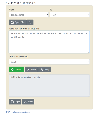
这是 MISO 转换以及我在 code composer cc2640r2 程序的 putty 控制台上看到的内容
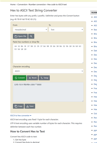


这是打印出来时控制台的样子


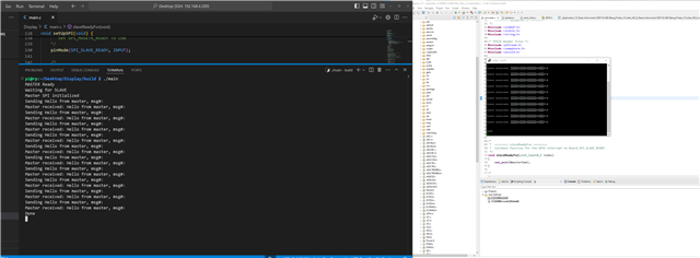
这就是我在两个 cc2640R2板之间获得的示例打印结果


  • 请注意,本文内容源自机器翻译,可能存在语法或其它翻译错误,仅供参考。如需获取准确内容,请参阅链接中的英语原文或自行翻译。

    您好!

    逻辑电平应该正常、RPi 使用的3.3V 电压应该与 CC2640R2兼容。
    您是否能彻底检查万用表上 RPi 的输出高电平以确认?

    此外、您能否确认以下内容?

    1. RPi 与 CC2640R2之间的接线正确、并从 CC2640R2的角度测量 MISO (DIO8)
    2. wiringSpi 中的 SPI 帧格式设置(对于 CC2640R2、为 SPI_POL0_PHA1)

    谢谢!
    Toby

  • 请注意,本文内容源自机器翻译,可能存在语法或其它翻译错误,仅供参考。如需获取准确内容,请参阅链接中的英语原文或自行翻译。

    是的、我可以看到数据正在从 MOSI 发送、但从 Raspberry Pi MOSI 引脚根本没有电压
    1.接线正确,来自 CC2640R2的 MISO 电压只有0.04伏

    2.不确定是否有方法设置 WiringPi 库的组帧。   

    这是 SPI wiringPi 文件的.c 文件

    /*
     * wiringPiSPI.c:
     *	Simplified SPI access routines
     *	Copyright (c) 2012-2015 Gordon Henderson
     ***********************************************************************
     * This file is part of wiringPi:
     *	github.com/.../
     *
     *    wiringPi is free software: you can redistribute it and/or modify
     *    it under the terms of the GNU Lesser General Public License as
     *    published by the Free Software Foundation, either version 3 of the
     *    License, or (at your option) any later version.
     *
     *    wiringPi is distributed in the hope that it will be useful,
     *    but WITHOUT ANY WARRANTY; without even the implied warranty of
     *    MERCHANTABILITY or FITNESS FOR A PARTICULAR PURPOSE.  See the
     *    GNU Lesser General Public License for more details.
     *
     *    You should have received a copy of the GNU Lesser General Public
     *    License along with wiringPi.
     *    If not, see <www.gnu.org/.../>.
     ***********************************************************************
     */
    
    
    #include <stdio.h>
    #include <unistd.h>
    #include <stdint.h>
    #include <stdlib.h>
    #include <fcntl.h>
    #include <errno.h>
    #include <string.h>
    #include <sys/ioctl.h>
    #include <asm/ioctl.h>
    #include <linux/spi/spidev.h>
    #include "wiringPi.h"
    #include "wiringPiSPI.h"
    
    
    // The SPI bus parameters
    //	Variables as they need to be passed as pointers later on
    
    //static const char       *spiDev0  = "/dev/spidev0.0" ;
    //static const char       *spiDev1  = "/dev/spidev0.1" ;
    static const uint8_t     spiBPW   = 8 ;
    static const uint16_t    spiDelay = 0 ;
    //datasheets.raspberrypi.com/.../cm4-datasheet.pdf
    const uint8_t     WPI_MaxSPINumbers   = 7 ;
    const uint8_t     WPI_MaxSPIChannels  = 3 ;
    
    
    static uint32_t    spiSpeeds [7][3] =
    {
     {0, 0, 0},
     {0, 0, 0},
     {0, 0, 0},
     {0, 0, 0},
     {0, 0, 0},
     {0, 0, 0},
     {0, 0, 0},
    };
    
    static int         spiFds [7][3] =
    {
     {-1, -1, -1},
     {-1, -1, -1},
     {-1, -1, -1},
     {-1, -1, -1},
     {-1, -1, -1},
     {-1, -1, -1},
     {-1, -1, -1},
    };
    
    
    int SPICheckLimits(const int number, const int channel) {
      if (channel<0 || channel>=WPI_MaxSPIChannels) {
        fprintf (stderr, "wiringPiSPI: Invalid SPI channel (%d, valid range 0-%d)", channel, WPI_MaxSPIChannels-1);
        return -EINVAL;
      }
      if (number<0 || number>=WPI_MaxSPINumbers) {
        fprintf (stderr, "wiringPiSPI: Invalid SPI number  (%d, valid range 0-%d)", number, WPI_MaxSPINumbers-1);
        return -EINVAL;
      }
    
      return 0;  //sucess
    }
    
    
    #define RETURN_ON_LIMIT_FAIL int ret = SPICheckLimits(number, channel); if(ret!=0) { return ret; };
    
    /*
     * wiringPiSPIGetFd:
     *	Return the file-descriptor for the given channel
     *********************************************************************************
     */
    
    int wiringPiSPIxGetFd(const int number, int channel)
    {
      if (SPICheckLimits(number, channel)!=0) {
        return -1;
      }
      return spiFds[number][channel];
    }
    
    int wiringPiSPIGetFd(int channel) {
      return wiringPiSPIxGetFd(0, channel);
    }
    
    
    /*
     * wiringPiSPIDataRW:
     *	Write and Read a block of data over the SPI bus.
     *	Note the data ia being read into the transmit buffer, so will
     *	overwrite it!
     *	This is also a full-duplex operation.
     *********************************************************************************
     */
    
    int wiringPiSPIxDataRW (const int number, const int channel, unsigned char *data, const int len)
    {
    
      RETURN_ON_LIMIT_FAIL
      if (-1==spiFds[number][channel]) {
        fprintf (stderr, "wiringPiSPI: Invalid SPI number/channel (need wiringPiSPIxSetupMode before read/write)");
        return -EBADF;
      }
    
      struct spi_ioc_transfer spi ;
    // Mentioned in spidev.h but not used in the original kernel documentation
    //	test program )-:
      memset (&spi, 0, sizeof (spi)) ;
    
      spi.tx_buf        = (unsigned long)data ;
      spi.rx_buf        = (unsigned long)data ;
      spi.len           = len ;
      spi.delay_usecs   = spiDelay ;
      spi.speed_hz      = spiSpeeds [number][channel] ;
      spi.bits_per_word = spiBPW ;
    
      return ioctl (spiFds[number][channel], SPI_IOC_MESSAGE(1), &spi) ;
    }
    
    int wiringPiSPIDataRW (int channel, unsigned char *data, int len) {
      return wiringPiSPIxDataRW(0, channel, data, len);
    }
    
    /*
     * wiringPiSPISetupMode:
     *	Open the SPI device, and set it up, with the mode, etc.
     *********************************************************************************
     */
    
    
    int wiringPiSPIxSetupMode(const int number, const int channel, const int speed, const int mode)
    {
      int fd ;
      char spiDev [32] ;
    
      RETURN_ON_LIMIT_FAIL
      if (mode<0 || mode>3) { // Mode is 0, 1, 2 or 3 original
        fprintf (stderr, "wiringPiSPI: Invalid mode (%d, valid range 0-%d)", mode, 3);
        return -EINVAL;
      }
    
      snprintf (spiDev, 31, "/dev/spidev%d.%d", number, channel) ;
      if ((fd = open (spiDev, O_RDWR)) < 0) {
        return wiringPiFailure (WPI_ALMOST, "Unable to open SPI device %s: %s\n", spiDev, strerror (errno)) ;
      }
      spiSpeeds [number][channel] = speed ;
      spiFds    [number][channel] = fd ;
    
    // Set SPI parameters.
    
      if (ioctl (fd, SPI_IOC_WR_MODE, &mode)            < 0)
        return wiringPiFailure (WPI_ALMOST, "SPI mode change failure: %s\n", strerror (errno)) ;
      
      if (ioctl (fd, SPI_IOC_WR_BITS_PER_WORD, &spiBPW) < 0)
        return wiringPiFailure (WPI_ALMOST, "SPI BPW change failure: %s\n", strerror (errno)) ;
    
      if (ioctl (fd, SPI_IOC_WR_MAX_SPEED_HZ, &speed)   < 0)
        return wiringPiFailure (WPI_ALMOST, "SPI speed change failure: %s\n", strerror (errno)) ;
    
      return fd ;
    }
    
    
    int wiringPiSPISetupMode (int channel, int speed, int mode) {
     return wiringPiSPIxSetupMode (0, channel, speed, mode);
    }
    
    
    /*
     * wiringPiSPISetup:
     *	Open the SPI device, and set it up, etc. in the default MODE 0
     *********************************************************************************
     */
    
    int wiringPiSPISetup (int channel, int speed) {
      return wiringPiSPIxSetupMode(0, channel, speed, 0) ;
    }
    
    
    int wiringPiSPIxClose (const int number, const int channel) {
    
      RETURN_ON_LIMIT_FAIL
      if (spiFds[number][channel]>0) {
        ret = close(spiFds[number][channel]);
      }
      spiSpeeds [number][channel] = 0 ;
      spiFds    [number][channel] = -1 ;
      return ret;
    }
    
    int wiringPiSPIClose (const int channel) {
      return wiringPiSPIxClose (0, channel);
    }


  • 请注意,本文内容源自机器翻译,可能存在语法或其它翻译错误,仅供参考。如需获取准确内容,请参阅链接中的英语原文或自行翻译。

    您是否注意到  以下各项的逻辑分析仪屏幕截图之间存在任何差异(每个仅进行一个事务):

    1. CC2640R2更新为 CC2640R2
    2. CC2640R2至 RPi

    关于 WiringPi、似乎并非所有模式都受支持: https://forums.raspberrypi.com/viewtopic.php?t=122918

    您是否考虑过其他 RPi SPI 代码?

    或者、您可以在 CC2640R2侧尝试每种模式以查看是否有更好的结果。

  • 请注意,本文内容源自机器翻译,可能存在语法或其它翻译错误,仅供参考。如需获取准确内容,请参阅链接中的英语原文或自行翻译。

    将模式切换到 帧格式的 SPI_POL1_PHA1来实现了这个诀窍!! 非常感谢您的帮助。  另外、如果有人使用 wiringPi 库  

    wiringPiSPIDataRW()函数指出它将数据从 MISO 写回同一缓冲区。 这在我尝试时并没有发生、因此我只使用了 wiringPi 设置函数初始化 SPI、但随后我复制了库中的函数并将它们放在主文件中。  您可以从 rxBuffer 中获取 MISO 数据。   
    下面是我的代码、如果任何其他人遇到问题并希望获得 spiMaster to spiSlave 模型、其中使用 CC2640R2作为从设备、使用 Raspberry Pi 作为主设备、他们可以进行健全性检查。   

    这是我从 main 调用以设置它的函数

    void setUpSPI(void) {
        wiringPiSetup();
    
        /* Set SPI_MASTER_READY To OUPUT 
           Set SPI_MASETR_READY To LOW  
        */
        pinMode(SPI_MASTER_READY, OUTPUT);
        digitalWrite(SPI_MASTER_READY, LOW);
        
        /* Set SPI_SLAVE_READY To INPUT 
           Set SPI_MASETR_READY To LOW  
        */
        pinMode(SPI_SLAVE_READY, INPUT);
    
        /*
         * Handshake - Set SPI_MASTER_READY HIGH to indicate master is ready
         * to run.  Wait SPI_SLAVE_READY to be HIGH.
         */
        digitalWrite(SPI_MASTER_READY, HIGH);
        printf("MASTER Ready\nWaiting for SLAVE\n");
        while(digitalRead(SPI_SLAVE_READY) == LOW) {}
        /*
            Handshake complete; now configure interrupt on Board_SPI_SLAVE_READY 
         */
        pullUpDnControl(SPI_SLAVE_READY, PUD_UP);
        wiringPiISR(SPI_SLAVE_READY, INT_EDGE_FALLING, &slaveReadyFxn);
    
        /*
           Create synchronization semaphore; the master will wait on this semaphore
           until the slave is ready.
        */
        int status = sem_init(&masterSem, 0, 0);
        if(status != 0) {
            printf("Failed to create semphore\n");
            while(1);
        }
    
        fd = wiringPiSPISetup(SPI_CHAN, SPI_SPEED);
        if(fd < 0) {
            printf("Unable to init SPI\n");
        } else {
            printf("Master SPI initialized\n");
        }
    
        digitalWrite(SPI_MASTER_READY, LOW);
        // strncpy((char*)masterTxBuffer, MASTER_MESSAGE, SPI_MSG_LENGTH);
        masterTxBuffer = MASTER_MESSAGE;
        sendMessage();
    }

    然后发送消息
    void sendMessage(void) {;
        for(int i = 0; i < MAX_LOOP; i++) {
    
            sem_wait(&masterSem);
            transferComplete = spiTransfer(masterTxBuffer, SPI_MSG_LENGTH);
            if(transferComplete) {
                printf("Master received: %s\n", spi.rx_buf);
            } else {
                printf("Unsuccessful master SPI transfer\n");
            }
    
            usleep(3000000);
        }
    
        printf("Done\n");
        wiringPiSPIClose(SPI_CHAN);
    }
    这就是 iringPi 辅助函数中的内容、但出于某种原因、他们不希望为开发者提供对 rxbuffer 的访问权限。  我只是将函数复制到主文件中、它运行得很好。
    int spiTransfer (unsigned char *data, const int len) {
    
      memset (&spi, 0, sizeof (spi)) ;
    
      spi.tx_buf        = (unsigned long)data ;
      spi.rx_buf        = (unsigned long)rx_buf ;
      spi.len           = len ;
      spi.delay_usecs   = spiDelay ;
      spi.speed_hz      = SPI_SPEED ;
      spi.bits_per_word = spiBPW ;
    
      return ioctl (fd, SPI_IOC_MESSAGE(1), &spi) ;
    }
  • 请注意,本文内容源自机器翻译,可能存在语法或其它翻译错误,仅供参考。如需获取准确内容,请参阅链接中的英语原文或自行翻译。

    很高兴听到您的设置现在正在运行、感谢您分享您的解决方案!