


线程中讨论的其他部件:LDC1000EVM, LDC1614, LDC1101, LDC3114
大家好,
直到最近,我还在使用 LDC1000EVM评估模块中的传感器。 我从 EVM上扣下了USB模块,并将不同的终端单独连接到我的微控制器。
下面是我为读取传感器的接近寄存器而编写的代码。 我的方法如下:
*我使用适当的寄存器值设置传感器
*然后,我通过使用无限循环来轮询接近寄存器
// Included Files

#define DLY 21
#include "preprocessor.h"
#include "F28x_Project.h"
#include "spi_globals.h"
#include "spi_defines.h"
#include "function_defs.h"

void scan_test(void);


void main(void)
{
// INITIALISATION
//

// SETUP CLOCK FREQUENCY
    EALLOW;
//        ClkCfgRegs.LOSPCP.bit.LSPCLKDIV = 0b100;
    EDIS;


// SETUP CODE
//

// PRELIMINARY STEPS
       InitSysCtrl();               // Step 1. Initialize System Control:

       InitSpiaGpio();              // Step 2. Initialize GPIO:
//       InitSpibGpio();              // SPIB initialisation

       DINT;                        // Step 3. Clear all interrupts:

       InitPieCtrl();               // Initialize PIE control registers to their default state.


// Disable CPU __interrupts and clear all CPU __interrupt flags:
       IER = 0x0000;
       IFR = 0x0000;

// Initialize the PIE vector table with pointers to the shell Interrupt Service Routines (ISR).
       InitPieVectTable();


// Step 4. Initialize the Device Peripherals:
       spi_fifo_init();     // Initialize the Spi FIFO
       spi_init();          // init SPI

// GPIO initialisation:
#if 0
       EALLOW;
       GpioCtrlRegs.GPBDIR.bit.GPIO61 = 1;              // This is to explicitly control chip select
       EDIS;
#endif


// COMMAND SECTION
//


// WRITE COMMANDS
//
#if 1
       // WRITE COMMANDS
           // 2. rp max
           write_command(ADR.Rp_MAX, 0x0E);
           rxdat = store();                         //read data into rxdat to clear INT_FLAG

           // 3. rp min
           write_command(ADR.Rp_MIN, 0x3A);
           rxdat = store();                         //read data into rxdat to clear INT_FLAG

           // 4. sensor frequency
           write_command(ADR.SEN_FREQ, 0x94);
           rxdat = store();                         //read data into rxdat to clear INT_FLAG

           // 5. ldc config
           write_command(ADR.LDC_CONF, 0x17);
           rxdat = store();                         //read data into rxdat to clear INT_FLAG

           // 6. clk config
           write_command(ADR.CLK_CFG, 0x02);
           rxdat = store();                         //read data into rxdat to clear INT_FLAG

           // 7. comparator threshold high lsb
           write_command(ADR.HI_LSB_CMP_LIM, 0x50);
           rxdat = store();                         //read data into rxdat to clear INT_FLAG

           // 8. comparator threshold high msb
           write_command(ADR.HI_MSB_CMP_LIM, 0x14);
           rxdat = store();                         //read data into rxdat to clear INT_FLAG

           // 9. comparator threshold low lsb
           write_command(ADR.LO_LSB_CMP_LIM, 0xC0);
           rxdat = store();                         //read data into rxdat to clear INT_FLAG

           // 10. comparator threshold low lsb
           write_command(ADR.LO_MSB_CMP_LIM, 0x12);
           rxdat = store();                         //read data into rxdat to clear INT_FLAG

           // 11. intb pin configuration
           write_command(ADR.INTB_CFG, 0x04);
           rxdat = store();                         //read data into rxdat to clear INT_FLAG

           //12. Power config
           write_command(ADR.PWR_CFG, 0x01);
           rxdat = store();                         //read data into rxdat to clear INT_FLAG
#endif

#if 1
       // READ COMMANDS
       //
           read(0x00);                      // Read device id: address 0x00
           device_id = store();             // Write data into variable to clear int_flag

           read(0x01);                      // Read Rp max: address 0x01
           rp_max = store();                // Write data into variable to clear int_flag

           read(0x02);                      // Read Rp_min: address 0x02
           rp_min = store();                // Write data into variable to clear int_flag

           read(0x03);                      // Read Sensor frequency: address 0x03
           sen_freq = store();              // Write data into variable to clear int_flag

           read(0x04);                      // Read LDC configuration: address 0x04
           ldc_cfg = store();               // Write data into variable to clear int_flag

           read(0x05);                      // Read clock configuration: address 0x05
           clk_cfg = store();               // Write data into variable to clear int_flag

           read(0x06);                      // Read comparator threshold high LSB: address 0x06
           lim_hi_lsb = store();            // Write data into variable to clear int_flag

           read(0x07);                      // Read comparator threshold high MSB: address 0x07
           lim_hi_msb = store();            // Write data into variable to clear int_flag

           read(0x08);                      // Read comparator threshold low LSB: address 0x08
           lim_lo_lsb = store();            // Write data into variable to clear int_flag

           read(0x09);                      // Read comparator threshold low MSB: address 0x09
           lim_lo_lsb = store();            // Write data into variable to clear int_flag

           read(0x0A);                      // Read INTB Pin configuration: address 0x0A
           intb_cfg = store();              // Write data into variable to clear int_flag

           read(0x0B);                      // Read Power configuration: address 0x0B
           pwr_cfg = store();               // Write data into variable to clear int_flag

           read(0x20);                      // Read status: address 0x20
           status = store();                // Write data into variable to clear int_flag


           // Test loop
           //
           for(;;)                          // TEST LOOP
           {
               read(0x21);                  // Read lsb proximity data: address 0x21
               proxdat_lsb = store();       // Write data into variable to clear int_flag

               read(0x22);                  // Read msb proximity data: address 0x22
               proxdat_msb = store();       // Write data into variable to clear int_flag

               data =  proxdat_msb<<8 | proxdat_lsb;

               DELAY_US(100);
           }
#endif

}

// FUNCTION DEFINITIONS:
//

void write_command(Uint16 wcom, Uint16 wdat)
{
    SpiaRegs.SPITXBUF = wcom<<8 | wdat;             // Concatenating command field and data field to transmit signal
    while(SpiaRegs.SPISTS.bit.BUFFULL_FLAG !=0){}   // Read only: set to 0 when tx'd data loaded into SPIDAT
    while(SpiaRegs.SPISTS.bit.INT_FLAG !=1){}       // Set to indicate SPI completed tx or rx
}


void read(Uint16 adr)
{
    adr = adr + 0x80;
    SpiaRegs.SPITXBUF = adr<<8 |0x00;                // Read command to transmit
    while(SpiaRegs.SPISTS.bit.BUFFULL_FLAG !=0){}   // Read only: set to 0 when tx'd data loaded into SPIDAT
    while(SpiaRegs.SPISTS.bit.INT_FLAG !=1){}       // Set to indicate SPI completed tx or rx
}

Uint16 store(void)
{
    rxdat = SpiaRegs.SPIRXBUF;                      // Store data in dummy variable rxdat
    return rxdat;                                   // Return value of stored data in variable
                                                    // Now by 'variable = store()' you can read data into variable
                                                    // Used for read commands
}
随附的是我正在使用的传感器的数据表:
e2e.ti.com/.../ldc1000_2D00_q1.pdf
LDC1000EVM模块的行为
在我的LDC1000EVM模块上,使用上述代码读取接近传感器。 接近寄存器中的数据对接近的导体作出响应,值相应增加和减少。
MIKROE LDC1000咔嗒板的行为
损坏以前的传感器后,我更换了MIKROE LDC1000咔嗒板。 运行相同的代码时,我发现以下行为:
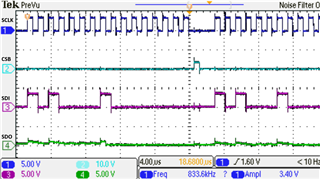
当我最初运行代码时,我可以读取接近寄存器以外的所有寄存器。 接近寄存器始终返回0x00。 注:所有其它寄存器都被正确写入和读取。 这是尝试读取接近寄存器的屏幕截图:
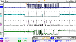
当我重新运行相同的代码时,我会从接近寄存器中读取数据,但是这次数据不会随着设备暴露在导体中而改变。 实际上,寄存器保持在相同的值-此值为0x2165。
我不知道为什么我会遇到这个问题。 以前,通过EVM板芯片,我获得了适当的读数。 我们在覆盆子PI板上运行此程序,我们再次获得了正确的值。 但是,当从TI主板运行该程序时,我得到了本文中概述的问题。
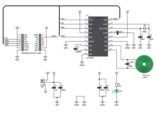
我可以看到两者之间的唯一区别是MIKROE点击板上的一个8 MHz振荡器晶体。 下面是LDC1000 MIKROE点击板的示意图:
另一个要提及的要点:
*在MIKROE触控板上,探测LC储罐线圈,我可以看到将导体靠近传感器的反应。 更改LDC1000传感器上的rp_min和rp_max寄存器也会影响此情况。 当接近寄存器返回零时,会观察到这种现象。
提前感谢
