

I am
currently developing the UART communication on the CM core with the usage of
the uDMA.
- ARM 编译器 版本18.12.5
- F2838x 支持库 v3.04.00.00
I try to
receive data from the RX channel of the UART in a mix between reading out the
FIFO directly and using the uDMA. The reason I do this mix is because i have
different frames with different lenghts. For this purpose, the first 3 bytes (header)
of each frame are read directly from the FIFO with the driverLib. The header describes the information
of the following data. After that I know exactly how much data follow. Now I
pass this task on to the uDMA in order to receive the further data. Here the
udma reports back it has received all the data but it happens too early (not
all data are on the UART already).
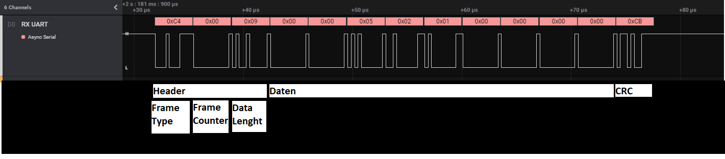
Frame:
A frame
consists of a header, data and one CRC byte. The header contains the type of
frame, a counter of the frame and, most importantly, the length of the
following data.
For
this example i have choose a small frame to represent the problem. In
the image i have a logic analyser recording how the example frames look like.
The header is
processed as follows. As soon as the FIFO is filled to 2/8 (UART_FIFO_RX2_8) an interrupt (UART_INT_RX) signals that the header should
be in the FIFO. They are read out with the usage of driverlib and processed.
This code is shown below.
Now I know
exactly how much data has to be received to collect the full frame. This should be done by the uDMA. The uDMA starts to receive data correctly, but reports back a finish much too
early. Not all data of the frame are on the UART at this time. This is shown in the next recording.

According
to the UDMA_ControlTable, the uDMA is also configured as i expect.

The data are
copyed in my buffer. I have partially filled the buffer with 0xFF before, that
can be ignored.
0xC4,
0x00 and 0x09 are received from the FIFO with the driverLib. After this the uDMA
starts work and collect the following bytes. After the 0x02 is received, the uDMA
sends the interrupt (UART_INT_DMATX). In this moment i have a capture of the memory.

The uDMA
fills the buffer with the wrong data until it reaches the dstEndAdress. What is
the reason for it? Can this happen if the rx FIFO is empty in the moment it
want to read?
The
initialization of the UART and the uDMA.
    void initUart()
    {
        SysCtl_enablePeripheral(SYSCTL_PERIPH_CLK_UART0);

        UART_setConfig(UART0_BASE, CM_CLK_FREQ , 3125000, (UART_CONFIG_WLEN_8 | UART_CONFIG_STOP_ONE | UART_CONFIG_PAR_EVEN));

        UART_enableModule(UART0_BASE);
        UART_enableFIFO(UART0_BASE);

        // Loop Back disabled
        UART_disableLoopback(UART0_BASE);

        UART_registerInterrupt(INT_UART0, &sioRxTxIntHandler);

        UART_setFIFOLevel(UART0_BASE, UART_FIFO_TX1_8, UART_FIFO_RX2_8);
        UART_clearInterruptStatus(UART0_BASE, UART_INT_RX | UART_INT_DMARX | UART_INT_DMATX);

        UART_enableInterrupt(UART0_BASE, UART_INT_RX | UART_INT_DMATX);

    }
void initDma()
{
SysCtl_enablePeripheral(SYSCTL_PERIPH_CLK_UDMA);
// Enable DMA for Tx and Rx events
//
UART_enableDMA(UART0_BASE, UART_DMA_TX | UART_DMA_RX);
//
// Enable UDMA
//
UDMA_enable(UDMA_BASE);
//
// Point at the control table to use for channel control structures.
//
UDMA_setControlBase(UDMA_BASE, ucControlTable);
UDMA_registerInterrupt(UDMA_ERR_INT, &dmaErrorInteruptHandler);
//
// Put the attributes in a known state for the uDMA software channel.
// These should already be disabled by default.
//
UDMA_disableChannelAttribute(UDMA_BASE, UDMA_CHANNEL_UART0_TX, UDMA_CH_ATTR_ALL);
UDMA_disableChannelAttribute(UDMA_BASE, UDMA_CHANNEL_UART0_RX, UDMA_CH_ATTR_ALL);
UDMA_enableChannelAttribute(UDMA_BASE, UDMA_CHANNEL_UART0_RX, UDMA_CH_ATTR_HIGH_PRIORITY | UDMA_CH_ATTR_USEBURST);
UDMA_setChannelControlParams(UDMA_BASE, (UDMA_CHANNEL_UART0_TX | UDMA_PRI_SELECT),
(UDMA_SIZE_8 | UDMA_SRC_INC_8 | UDMA_DST_INC_NONE
| UDMA_ARB_16));
UDMA_setChannelControlParams(UDMA_BASE, (UDMA_CHANNEL_UART0_RX | UDMA_PRI_SELECT),
(UDMA_SIZE_8 | UDMA_SRC_INC_NONE | UDMA_DST_INC_8
| UDMA_ARB_16 | UDMA_NEXT_USEBURST));
}The transfer parameters of the uDMA filled like in code below. I have try the UDMA_MODE_AUTO and the UDMA_MODE_BASIC with the same results.
    void rxConfigDMA(uint8_t* rxBufferDma, uint8_t transferSize)
    {
        UDMA_setChannelTransferParams(UDMA_BASE, (UDMA_CHANNEL_UART0_RX | UDMA_PRI_SELECT),
                                     (void *)(UART0_BASE + UART_O_DR), rxBufferDma, UDMA_MODE_AUTO,
                                     transferSize);
    }
中断处理程序如下所示:
  __attribute__((ramfunc)) __interrupt void sioRxTxIntHandler(void)
    {
        isrStatusMask = UART_getInterruptStatus(UART0_BASE, UART_MASKED_INT);

        // Received Header + Data Byte
        // Interrupt called if 4 Byte in FIFO (3 byte Header + 1 Data byte)
        if ((isrStatusMask & UART_INT_RX) == UART_INT_RX)
        {
            UART_clearInterruptStatus(UART0_BASE, UART_INT_RX);

            while (UART_isDataAvailable(UART0_BASE))
            {
                isrByteRead = UART_readCharNonBlocking(UART0_BASE);

                // reads data until a new frame is detected ore fifo empty
                if (!(stsCtrl.Control.Field.ReceivingFrame))  // only a control flag
                {
                    // DSO2X_FT_CYCLIC_DATA_EXCH == 0xC4
                    if ((isrByteRead == DSO2X_FT_CYCLIC_DATA_EXCH) || (isrByteRead == DSO2X_FT_ACYCLIC) || (isrByteRead == DSO2X_FT_ERROR_FRAME))
                    {
                        // reset my buffer
                        clearSioBuffer(&DSO2X_RxBuf[stsCtrl.Control.Field.RxWrBufIdx]);
                        // now a frame is in receiving mode
                        stsCtrl.Control.Field.ReceivingFrame = 1; // only a flag for control
                    }

	            // add received Byte to buffer
                if (stsCtrl.Control.Field.ReceivingFrame)
                {
                    DSO2X_RxBuf[stsCtrl.Control.Field.RxWrBufIdx].F.raw[DSO2X_RxBuf[stsCtrl.Control.Field.RxWrBufIdx].ByteCount] = isrByteRead;
                    DSO2X_RxBuf[stsCtrl.Control.Field.RxWrBufIdx].ByteCount++;
                }

                // DSO2X_FRAME_HEAD_SIZE = 3
                if (DSO2X_RxBuf[stsCtrl.Control.Field.RxWrBufIdx].ByteCount >= DSO2X_FRAME_HEAD_SIZE)
                {
                    // calculate the lenght that should received by the uDMA       DSO2X_FRAME_HEAD_SIZE = 3     DSO2X_FRAME_BCC_SIZE = 1
                    isrDmaReadLenght = DSO2X_RxBuf[stsCtrl.Control.Field.RxWrBufIdx].F.header.BLen + DSO2X_FRAME_HEAD_SIZE - DSO2X_RxBuf[stsCtrl.Control.Field.RxWrBufIdx].ByteCount + DSO2X_FRAME_BCC_SIZE;
                    if ((isrDmaReadLenght > 0) && ((isrDmaReadLenght + DSO2X_RxBuf[stsCtrl.Control.Field.RxWrBufIdx].ByteCount) < DSO2X_MAX_FRAME_SIZE))
                    {
                        if (!UDMA_isChannelEnabled(UDMA_BASE, UDMA_CHANNEL_UART0_RX))
                        {
                            UART_disableInterrupt(UART0_BASE, UART_INT_RX);
                            UART_enableInterrupt(UART0_BASE, UART_INT_DMARX);
                            UART_enableDMA(UART0_BASE, UART_DMA_RX);
                            rxConfigDMA(DSO2X_RxBuf[stsCtrl.Control.Field.RxWrBufIdx].F.raw + DSO2X_RxBuf[stsCtrl.Control.Field.RxWrBufIdx].ByteCount, isrDmaReadLenght);
                            DSO2X_RxBuf[stsCtrl.Control.Field.RxWrBufIdx].ByteCount += isrDmaReadLenght;
                            UDMA_enableChannel(UDMA_BASE, UDMA_CHANNEL_UART0_RX);
                        }

                        break;
                    }
                    else
                    {
                        stsCtrl.Control.Field.RxWrBufIdx++;
                        stsCtrl.Control.Field.ReceivingFrame = 0;
                    }
                }
            }
        }

        if ((isrStatusMask & UART_INT_DMARX) == UART_INT_DMARX)  // DMA Controller Finished Receiving Frame
        {
            UART_disableDMA(UART0_BASE, UART_DMA_RX);

            // reset interrupt mask
            UART_clearInterruptStatus(UART0_BASE, UART_INT_DMARX);
	        // disable the dma interrupt
            UART_disableInterrupt(UART0_BASE, UART_INT_DMARX);
	        // enable interrupt to receive the next header
            UART_enableInterrupt(UART0_BASE, UART_INT_RX);

	        // here are done some with the received data
	        // …

        }
    }
附加说明
如果我使用 optlevel=off 编译代码、代码会更慢。 这会导致 uDMA 从这里开始的工作时间较晚。 这意味着当完整的帧已经存在时、UDMA 开始从 FIFO 中收集数据。 在本例中、它可以工作、但它不具有可调性、因为我必须快速、并且帧可以比示例中大得多。
