This thread has been locked.

If you have a related question, please click the "Ask a related question" button in the top right corner. The newly created question will be automatically linked to this question.

[参考译文] TMS320F28374S:为了安全完成事务、需要相对较长的延迟的 I2C 事务

Guru**** 1133870 points
Other Parts Discussed in Thread: DAC7578, TCA9555, C2000WARE
请注意,本文内容源自机器翻译,可能存在语法或其它翻译错误,仅供参考。如需获取准确内容,请参阅链接中的英语原文或自行翻译。

https://e2e.ti.com/support/microcontrollers/c2000-microcontrollers-group/c2000/f/c2000-microcontrollers-forum/1019094/tms320f28374s-i2c-transactions-requiring-a-relatively-long-delay-in-order-to-safely-complete-transactions

器件型号:TMS320F28374S
主题中讨论的其他器件:DAC7578TCA9555C2000WARE

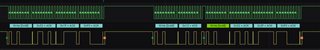
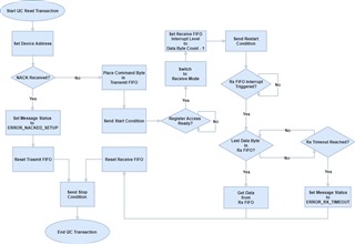
大家好、我正在为我的系统处理 I2C 事务、我注意到为了让我的事务安全完成、我在每个事务之间需要大约75uS 的延迟、以便所有事务都能在停止条件下正常完成。 在大约60us 或更短的延迟时间内、我开始失去总线稳定性、之前事务中的字节出现在下一个事务中、错过了停止条件和/或最终完全锁定总线。 是否有人可能对可能发生的原因有任何见解? 在延迟情况下、一切运行顺利、但如果可能、我想减少这一延迟量。

谢谢!

  • 请注意,本文内容源自机器翻译,可能存在语法或其它翻译错误,仅供参考。如需获取准确内容,请参阅链接中的英语原文或自行翻译。

    尊敬的罗纳尔杜斯、您好!

    您能否提供有关 I2C 实现的更多详细信息? 下面是一些问题:

    1. F2837xS 是主器件吗? 您连接的是哪些 I2C 器件? 什么 I2C 时钟速度?
    2. 您是如何实现该协议的? 即写入/读取序列中的字节数?
      1. 写入/读取序列长度可能长于60us 延迟?
    3. 您能否提供 I2C 代码的一些片段?

    最棒的

    Kevin

  • 请注意,本文内容源自机器翻译,可能存在语法或其它翻译错误,仅供参考。如需获取准确内容,请参阅链接中的英语原文或自行翻译。

    感谢您的回答! 以下是您需要的信息:

    1.  是的、很抱歉 F2837xS 是主器件、I2C 总线上没有其他主器件 我正在连接 TI DAC7578、TI TCA9555 IO 扩展器和 RTCC 模块。 时钟速度为200MHz。

    2. 读取/写入序列

      1. DAC
        1. 写入序列总共为3个数据字节(命令/访问字节和2个 DAC 输入字节)
        2. 读取序列为1字节以请求数据、2字节以读回。  

      2. IO 扩展器
        1. 总共2个数据字节的写入序列
        2. 读取序列为1字节请求、1字节返回请求端口的引脚状态

      3. RTCC
        1. 写序列总共为8个数据字节(1个用于命令/访问、7个用于时间参数)
        2. 读取序列为1个用于请求的数据字节和7个字节的回读

    3. 当然! 下面是我制作的一些 I2C 代码:
      1. /*-------------------*/
        /* I2C API Functions */
        /*-------------------*/
        
        
        /*-----------*/
        /* Variables */
        /*-----------*/
        volatile I2C_MESSAGE_STRUCT writeDAC =
        {
            .messageState = TRANSMITTING,
            .messageStatus = NO_ERROR,
            .slaveChipAddress = DAC1_SLAVE_ADDRESS,
            .dataByteCount = 2,
            .commandByte = WRITE_DAC,
            .dataByteBuffer = { 0x00U, 0x00U, 0,0,0,0,0,0,0,0,0,0,0,0,0,0 }
        };
        
        volatile I2C_MESSAGE_STRUCT readDAC =
        {
            .messageState = RECEIVING,
            .messageStatus = NO_ERROR,
            .slaveChipAddress = DAC1_SLAVE_ADDRESS,
            .dataByteCount = 2,
            .commandByte = READ_DAC,
            .dataByteBuffer = { 0,0,0,0,0,0,0,0,0,0,0,0,0,0,0,0 }
        };
        
        volatile I2C_MESSAGE_STRUCT rtcGetTimeMsg =
        {
            .messageState = RECEIVING,
            .messageStatus = NO_ERROR,
            .slaveChipAddress = RTC_SLAVE_ADDRESS,
            .dataByteCount = 7,
            .commandByte = RTC_SECONDS_INDEX,
            .dataByteBuffer = {0,0,0,0,0,0,0,0,0,0,0,0,0,0,0,0}
        };
        
        // Read the Weekday Register to Get the Oscillator Status
        volatile I2C_MESSAGE_STRUCT rtcGetOscStatusMsg =
        {
            .messageState = RECEIVING,
            .messageStatus = NO_ERROR,
            .slaveChipAddress = RTC_SLAVE_ADDRESS,
            .dataByteCount = 1,
            .commandByte = RTC_WEEKDAY_INDEX,
            .dataByteBuffer = {0,0,0,0,0,0,0,0,0,0,0,0,0,0,0,0}
        };
        
        volatile I2C_MESSAGE_STRUCT writeIOX =
        {
            .messageState = TRANSMITTING,
            .messageStatus = NO_ERROR,
            .slaveChipAddress = IO_EXPANDER_A_SLAVE_ADDRESS,
            .dataByteCount = 1,
            .commandByte = IOX_WRITE_PIN,
            .dataByteBuffer = {0,0,0,0,0,0,0,0,0,0,0,0,0,0,0,0}
        };
        
        volatile I2C_MESSAGE_STRUCT readIOX =
        {
            .messageState = RECEIVING,
            .messageStatus = NO_ERROR,
            .slaveChipAddress = IO_EXPANDER_A_SLAVE_ADDRESS,
            .dataByteCount = 1,
            .commandByte = IOX_READ_PIN,
            .dataByteBuffer = {0,0,0,0,0,0,0,0,0,0,0,0,0,0,0,0}
        };
        
        /*---------------*/
        /* I2C Functions */
        /*---------------*/
        /*---------------------------------------------------------------------------*/
        /** @brief Public I2C Read function
         * Posts the I2C Read Transaction to the I2C Manager's Mailbox
         *
         * @param [I2C_MESSAGE_STRUCT* msg] pointer to I2C message struct
         * @param [const I2C_SETTINGS_STRUCT* settings] pointer to I2C settings struct
         *
         * @returns transaction status - success (true) or failure (false)
         *//*------------------------------------------------------------------------*/
        static bool_dtc I2C_read(const I2C_SETTINGS_STRUCT* settings, volatile I2C_MESSAGE_STRUCT *msg, I2C_DEVICE_ID deviceID)
        {
            bool_dtc transactionStatus = true;
            i2cRead(settings, msg);
            DEVICE_DELAY_US(I2C_BUS_DELAY);
        
            if(NO_ERROR != msg->messageStatus)
            {
                if(WARNING_SPURIOUS_INTERRUPT == msg->messageStatus)
                {
                   ++i2cStatistics[deviceID].statsSpuriuousInterrupts;
                }
                else
                {
                   ++i2cStatistics[deviceID].statsReadsFailure;
                }
                transactionStatus = false;
            }
            else
            {
               ++i2cStatistics[deviceID].statsReadsSuccess;
            }
        
            return transactionStatus;
        }
        
        /*---------------------------------------------------------------------------*/
        /** @brief Public I2C Write function
         * Posts the I2C Write Transaction to the I2C Manager's Mailbox
         *
         * @param [I2C_MESSAGE_STRUCT* msg] pointer to I2C message struct
         * @param [const I2C_SETTINGS_STRUCT* settings] pointer to I2C settings struct
         *
         * @returns transaction status - success (true) or failure (false)
         *//*------------------------------------------------------------------------*/
        static bool_dtc I2C_write(const I2C_SETTINGS_STRUCT* settings, volatile I2C_MESSAGE_STRUCT* msg, I2C_DEVICE_ID deviceID)
        {
            bool_dtc transactionStatus = true;
        
            i2cWrite(settings, msg);
            DEVICE_DELAY_US(I2C_BUS_DELAY);
        
            if(NO_ERROR != msg->messageStatus)
            {
                if(WARNING_SPURIOUS_INTERRUPT == msg->messageStatus)
                {
                    ++i2cStatistics[deviceID].statsSpuriuousInterrupts;
                }
                else
                {
                    ++i2cStatistics[deviceID].statsWriteFailure;
                }
                transactionStatus = false;
            }
            else
            {
                ++i2cStatistics[deviceID].statsWriteSuccess;
            }
        
            return transactionStatus;
        }
        
        /*---------------*/
        /* DAC Functions */
        /*---------------*/
        /*---------------------------------------------------------------------------*/
        /** @brief Write DAC
         *
         * Public DAC Write Function to start an I2C Write Transaction
         *
         * @param [dac] pointer to an instance of DAC_STRUCT
         * @param [deviceID] The I2C Device ID
         *
         * @returns true/false based on transaction success status
         *//*------------------------------------------------------------------------*/
        bool_dtc DAC_write(DAC_STRUCT *dac, I2C_DEVICE_ID deviceID)
        {
            bool_dtc i2cTransactionSuccessful = false;
            DAC_PN partNumber = -1;
        
            switch(deviceID)
            {
                case DAC1:
                    writeDAC.slaveChipAddress = DAC1_SLAVE_ADDRESS;
                    partNumber = DAC_TI_DAC7578;
                    break;
        
                case DAC2:
                    writeDAC.slaveChipAddress = DAC2_SLAVE_ADDRESS;
                    break;
        
                default:
                    break; //Device Not Found
            }
        
            i2cTransactionSuccessful = dac_translateToI2C(dac, &writeDAC, partNumber);
        
            if(i2cTransactionSuccessful)
            {
                writeDAC.commandByte = WRITE_DAC | dac->channel;
                i2cTransactionSuccessful = I2C_write(&i2cASettings, &writeDAC, deviceID);
            }
        
            return i2cTransactionSuccessful;
        }
        
        /*---------------------------------------------------------------------------*/
        /** @brief Read DAC
         *
         * Public DAC Read Function to start an I2C Read Transaction
         *
         * @param [dac] pointer to an instance of DAC_STRUCT
         * @param [deviceID] The I2C Device ID
         *
         * @returns true/false based on transaction success status
         *//*------------------------------------------------------------------------*/
        bool_dtc DAC_read(DAC_STRUCT *dac, I2C_DEVICE_ID deviceID)
        {
            bool_dtc i2cTransactionSuccessful = false;
            DAC_PN partNumber = -1;
        
            switch(deviceID)
            {
                case DAC1:
                    readDAC.slaveChipAddress = DAC1_SLAVE_ADDRESS;
                    partNumber = DAC_TI_DAC7578;
                    break;
        
                case DAC2:
                    readDAC.slaveChipAddress = DAC2_SLAVE_ADDRESS;
                    break;
        
                default:
                    break; //Device Not Found
            }
        
            readDAC.commandByte = READ_DAC | dac->channel;
            i2cTransactionSuccessful = I2C_read(&i2cASettings, &readDAC, deviceID);
        
            if(i2cTransactionSuccessful)
            {
                i2cTransactionSuccessful = dac_translateFromI2C(dac, &readDAC, partNumber);
            }
        
            return i2cTransactionSuccessful;
        }
        
        /*---------------*/
        /* RTC Functions */
        /*---------------*/
        /*---------------------------------------------------------------------------*/
        /** @brief Initializes the RTC
         *  @param [deviceID] The I2C Device ID
         *//*------------------------------------------------------------------------*/
        bool_dtc RTC_init(I2C_DEVICE_ID deviceID)
        {
            bool_dtc i2cTransactionStatus = false;
            RTCTimeFormat defaultDate =
            {
                .year    = 0x21,
                .month   = 0x04,
                .date    = 0x25,
                .weekday = 0x01,
                .hours   = 0x10,
                .minutes = 0x30,
                .seconds = 0x30
            };
        
            i2cTransactionStatus = I2C_read(&i2cASettings, &rtcGetOscStatusMsg, deviceID);
        
            //If the I2C Read was successful and the Oscillator is NOT running
            if(i2cTransactionStatus
                && (RTC_OSCRUN_STATUS != (rtcGetOscStatusMsg.dataByteBuffer[0] & RTC_OSCRUN_STATUS)))
            {
                i2cTransactionStatus = RTC_setTime(&defaultDate, deviceID);
            }
        
            return i2cTransactionStatus;
        }
        
        /*---------------------------------------------------------------------------*/
        /** @brief read time from RTC device
         *
         * Sends the get date command to device, then converts the BCD digits to
         * integers populated into the out pointer structure.
         *
         * @param [timeStruct] pointer to an instance of RTCTimeFormat structure
         * @param [deviceID] The I2C Device ID
         *
         * @returns true/false based on transaction success status
         *//*------------------------------------------------------------------------*/
        bool_dtc RTC_getTime(RTCTimeFormat* timeStruct, I2C_DEVICE_ID deviceID)
        {
            bool_dtc i2cTransactionSuccessful = false;
        
            i2cTransactionSuccessful = I2C_read(&i2cASettings, &rtcGetTimeMsg, deviceID);
        
            if(i2cTransactionSuccessful)
            {
                i2cTransactionSuccessful = rtc_translateFromI2C(timeStruct, &rtcGetTimeMsg);
            }
        
            return i2cTransactionSuccessful;
        }
        
        /*---------------------------------------------------------------------------*/
        /** @brief set time on RTC device
         *
         * Converts the time/date data from decimal to BCD and builds it into the I2C message.
         * Then sends the message to RTC to set the new time/date.
         *
         * @param [timeStruct] pointer to an instance of RTCTimeFormat structure
         * @param [deviceID] The I2C Device ID
         *
         * @returns true/false based on transaction success status
         *//*------------------------------------------------------------------------*/
        bool_dtc RTC_setTime(RTCTimeFormat* timeStruct, I2C_DEVICE_ID deviceID)
        {
            bool_dtc i2cTransactionSuccessful = false;
        
            i2cTransactionSuccessful = rtc_translateToI2C(timeStruct, &rtcSetTimeMsg);
        
            if(i2cTransactionSuccessful)
            {
                // Disable the RTC oscillator
                i2cTransactionSuccessful = I2C_write(&i2cASettings, &rtcStopOscillatorMsg, deviceID);
        
                // Transmit the time structure to the RTC
                if(i2cTransactionSuccessful)
                {
                    i2cTransactionSuccessful = I2C_write(&i2cASettings, &rtcSetTimeMsg, deviceID);
                    Board_deviceDelayUs(I2C_BUS_DELAY); //Extra Delay Required for RTC Set Time
                }
        
                if(i2cTransactionSuccessful)
                {
                    // Enable the RTC oscillator
                    rtcStartOscillatorMsg.dataByteBuffer[RTC_SECONDS_INDEX] |= rtcSetTimeMsg.dataByteBuffer[RTC_SECONDS_INDEX];
                    i2cTransactionSuccessful = I2C_write(&i2cASettings, &rtcStartOscillatorMsg, deviceID);
                }
            }
        
            return i2cTransactionSuccessful;
        }
        
        /*---------------------------------------------------------------------------*/
        /** @brief Writes to an IO Expander on the I2C Bus
         *
         * Writes the Pin Status to the Selected Pins in the IOX_STRUCT
         *
         * @param [*iox] pointer to an instance of IOX_STRUCT
         * @param [deviceID] I2C Device ID
         *
         * @returns true/false based on transaction success status
         *//*------------------------------------------------------------------------*/
        bool_dtc IOX_write(IOX_STRUCT *iox, I2C_DEVICE_ID deviceID)
        {
            bool_dtc i2cTransactionSuccessful = false;
        
            switch(deviceID)
            {
                case IOXA:
                    writeIOX.slaveChipAddress = IO_EXPANDER_A_SLAVE_ADDRESS;
                    break;
        
                case IOXB:
                    writeIOX.slaveChipAddress = IO_EXPANDER_B_SLAVE_ADDRESS;
                    break;
        
                default:
                    break; //Device Not Found
            }
        
            writeIOX.commandByte = IOX_WRITE_PIN;
            i2cTransactionSuccessful = iox_translateToI2C(iox, &writeIOX, currentPinStatusIOX);
        
            if(i2cTransactionSuccessful)
            {
                i2cTransactionSuccessful = I2C_write(&i2cASettings, &writeIOX, deviceID);
            }
        
            return i2cTransactionSuccessful;
        }
        
        /*---------------------------------------------------------------------------*/
        /** @brief Reads from an IO Expander on the I2C Bus
         *
         * Reads the Pin Status from the Selected Pins in the IOX_STRUCT
         *
         * @param [*iox] pointer to an instance of IOX_STRUCT
         * @param [deviceID] I2C Device ID
         *
         * @returns true/false based on transaction success status
         *//*------------------------------------------------------------------------*/
        bool_dtc IOX_read(IOX_STRUCT *iox, I2C_DEVICE_ID deviceID)
        {
            bool_dtc i2cTransactionSuccessful = false;
            iox->pinStatus = IOX_PIN_DONT_CARE;
        
                switch(deviceID)
                {
                    case IOXA:
                        readIOX.slaveChipAddress = IO_EXPANDER_A_SLAVE_ADDRESS;
                        break;
        
                    case IOXB:
                        readIOX.slaveChipAddress = IO_EXPANDER_B_SLAVE_ADDRESS;
                        break;
        
                    default:
                        break; //Device Not Found
                }
        
                readIOX.commandByte = IOX_READ_PIN;
                i2cTransactionSuccessful = iox_translateToI2C(iox, &readIOX, currentPinStatusIOX);
        
                if(i2cTransactionSuccessful)
                {
                    i2cTransactionSuccessful = I2C_read(&i2cASettings, &readIOX, deviceID);
                }
        
                if(i2cTransactionSuccessful)
                {
                    i2cTransactionSuccessful = iox_translateFromI2C(iox, &readIOX);
                }
        
                return i2cTransactionSuccessful;
        }
      2. /*-------------------*/
        /* I2C HAL Functions */
        /*-------------------*/
        
        /*-----------------------------------------------------------------------------
         * Types (typedefs, structs, class declarations)
         *---------------------------------------------------------------------------*/
        /**
         * Dummy message struct to ensure currTxMsgPtr always
         * points to a valid memory location
         */
        volatile static I2C_MESSAGE_STRUCT dummyMsg =
        {
            .messageState = INACTIVE,
            .messageStatus = NO_ERROR,
            .slaveChipAddress = 1,
            .dataByteCount = 16,
            .commandByte = 0x00U,
            .dataByteBuffer = {0,0,0,0,0,0,0,0,0,0,0,0,0,0,0,0}
        };
        
        /*-----------------------------------------------------------------------------
         * Static "private" (file scope) variables
         *---------------------------------------------------------------------------*/
        /**
         * Current message pointers are used by the ISR to track which operation
         * is being executed on the I2C bus.
         * I point both the Tx and Rx Message Pointers to the dummyMsg at initialization
         * so that the pointers aren't pointing to random memory locations.
         */
        static volatile I2C_MESSAGE_STRUCT *currTxMsgPtr = &dummyMsg;
        static volatile I2C_MESSAGE_STRUCT *currRxMsgPtr = &dummyMsg;
        
        /*-----------------------------------------------------------------------------
         * Implementations of static "private" (file scope) functions
         *---------------------------------------------------------------------------*/
        
        /*---------------------------------------------------------------------------*/
        /** @brief Reset the indicated I2C FIFO
         *
         * This function resets the indicated I2C FIFO
         * @param [uint32_dtc base] base address of the I2C module
         * @param [I2C_FIFO_TYPE fifoType] The type of FIFO to reset, either TX or RX
         *//*------------------------------------------------------------------------*/
        static void I2C_resetFIFO(uint32_dtc base)
        {
            I2C_disableFIFO(base);
            I2C_enableFIFO(base);
        }
        
        /*---------------------------------------------------------------------------*/
        /** @brief Function called by the FIFO Interrupts
         *
         * This function handles what to do with the information in the FIFOs
         * @param [I2C_SETTINGS_STRUCT* settings] pointer to I2C settings struct
         *//*------------------------------------------------------------------------*/
        void i2cFIFOInterruptHandler(const I2C_SETTINGS_STRUCT *settings)
        {
            uint32_dtc base = settings->i2cBaseAddr;
        
            uint32_dtc intStatus = I2C_getInterruptStatus(base);
        
            //Interrupt is from the Receive FIFO
            if(I2C_INT_RXFF == (intStatus & I2C_INT_RXFF))
            {
                I2C_sendStopCondition(base);
        
                uint32_dtc byteWaitCounter = 0;
                while((byteWaitCounter < I2C_RX_TIMEOUT)
                        && ((I2C_RxFIFOLevel)currRxMsgPtr->dataByteCount != I2C_getRxFIFOStatus(base)))
                {
                    ++byteWaitCounter;
                }
        
                if(byteWaitCounter != I2C_RX_TIMEOUT)
                {
                    for(int16_dtc i = 0; i < currRxMsgPtr->dataByteCount; ++i)
                    {
                       currRxMsgPtr->dataByteBuffer[i] = I2C_getData(base);
                    }
                }
                else
                {
                    currRxMsgPtr->messageStatus = ERROR_RX_TIMEOUT;
                }
        
                I2C_resetFIFO(base);
                currRxMsgPtr = &dummyMsg;
            }
        
            else //Interrupt is from the Transmit FIFO
            {
                currTxMsgPtr = &dummyMsg;
            }
        
            I2C_clearInterruptStatus(base, (uint32_dtc)(I2C_INT_TXFF | I2C_INT_RXFF));
            I2C_setFIFOInterruptLevel(base, I2C_FIFO_TXEMPTY, I2C_FIFO_RXFULL);
            I2C_disableFIFO(base);
        }
        
        /*------------------------------------------------------------------------------*/
        /** @brief Helper Function called by the I2C Interrupt Handler for NACKs
         *
         * This function handles the NACK interrupt from the I2C Module
         * @param [I2C_SETTINGS_STRUCT* settings] pointer to I2C settings struct
         *//*------------------------------------------------------------------------*/
        static void i2cInterrputHandler_NACK(const I2C_SETTINGS_STRUCT *settings)
        {
            uint32_dtc base = settings->i2cBaseAddr;
        
            //Reset the TX FIFO to clear any data inside of it
            I2C_resetFIFO(base);
            I2C_clearInterruptStatus(base, (uint32_dtc)I2C_INT_TXFF);
        
            //Clear NACK Status and Interrupt
            I2C_clearStatus(base, I2C_STS_NO_ACK);
            I2C_clearInterruptStatus(base, I2C_INT_NO_ACK);
        
            //Report that the Message was Nacked
            if(INACTIVE != currTxMsgPtr->messageState)
            {
                currTxMsgPtr->messageStatus = ERROR_NACKED_SETUP;
                currTxMsgPtr = &dummyMsg;
            }
            else //(INACTIVE == currTxMsgPtr->messageState) thus this is an Rx NACK
            {
                currRxMsgPtr->messageStatus = ERROR_NACKED_SETUP;
                currRxMsgPtr = &dummyMsg;
            }
        
            I2C_sendStopCondition(base);
        }
        
        /*---------------------------------------------------------------------------------*/
        /** @brief Helper Function called by the I2C Interrupt Handler for REG_ACCESS_RDY
         *
         * This function handles the REG_ACCESS_RDY Interrupt from the I2C Module
         * @param [I2C_SETTINGS_STRUCT* settings] pointer to I2C settings struct
         *//*------------------------------------------------------------------------------*/
        static void i2cInterruptHandler_RegAccesRdy(const I2C_SETTINGS_STRUCT *settings)
        {
            if(INACTIVE != currRxMsgPtr->messageState)
            {
                uint32_dtc base =  settings->i2cBaseAddr;
        
                I2C_clearInterruptStatus(base, I2C_INT_REG_ACCESS_RDY);
                I2C_disableFIFO(base);
                I2C_enableFIFO(base);
                I2C_disableInterrupt(base, (uint32_dtc)(I2C_INT_TXFF | I2C_INT_RXFF));
                I2C_clearInterruptStatus(base, (uint32_dtc)(I2C_INT_TXFF | I2C_INT_RXFF));
                I2C_setConfig(base, (uint16_dtc)I2C_MASTER_RECEIVE_MODE);
                I2C_setDataCount(base, currRxMsgPtr->dataByteCount);
                I2C_enableInterrupt(base, (uint32_dtc)I2C_INT_RXFF);
                I2C_setFIFOInterruptLevel(base, I2C_FIFO_TXEMPTY, (I2C_RxFIFOLevel)(currRxMsgPtr->dataByteCount - 1));
                I2C_sendStartCondition(base);
            }
        }
        
        /*------------------------------------------------------------------------------------*/
        /** @brief Helper Function called by the I2C Interrupt Handler for Spurious Interrupts
         *
         * This function handles Spurious Interrupts from the I2C Module
         * @param [I2C_SETTINGS_STRUCT* settings] pointer to I2C settings struct
         *//*--------------------------------------------------------------------------------*/
        static void i2cInterrputHandler_SpuriousInt(const I2C_SETTINGS_STRUCT *settings)
        {
            //Report that the Message was Nacked
            if(INACTIVE != currTxMsgPtr->messageState)
            {
                currTxMsgPtr->messageStatus = WARNING_SPURIOUS_INTERRUPT;
                currTxMsgPtr = &dummyMsg;
            }
            else //(INACTIVE != currRxMsgPtr->messageState)
            {
                currRxMsgPtr->messageStatus = WARNING_SPURIOUS_INTERRUPT;
                currRxMsgPtr = &dummyMsg;
            }
        
            I2C_clearInterruptStatus(settings->i2cBaseAddr, I2C_STR_INTMASK);
        }
        
        /*-----------------------------------------------------------------------------
         * Implementations of "public" API
         *---------------------------------------------------------------------------*/
        /*---------------------------------------------------------------------------*/
        /** @brief Function called by the I2C ISR
         * This function handles the interrupts on the I2C Bus
         *
         * @param [I2C_SETTINGS_STRUCT *setting] - a pointer to the I2C settings
         * for the module that generated the interrupt
         *//*------------------------------------------------------------------------*/
        void i2cInterruptHandler(const I2C_SETTINGS_STRUCT *settings)
        {
            uint32_t base = settings->i2cBaseAddr;
            I2C_InterruptSource intSource = I2C_getInterruptSource(base);
        
            switch (intSource)
            {
                case I2C_INTSRC_NONE:
                case I2C_INTSRC_RX_DATA_RDY:
                case I2C_INTSRC_TX_DATA_RDY:
                    break;
        
                case I2C_INTSRC_NO_ACK:
                    i2cInterrputHandler_NACK(settings);
                    break;
        
                case I2C_INTSRC_REG_ACCESS_RDY:
                    i2cInterruptHandler_RegAccesRdy(settings);
                    break;
        
                case I2C_INTSRC_STOP_CONDITION:
                    I2C_disableInterrupt(base, (uint32_dtc)(I2C_INT_TXFF | I2C_INT_RXFF));
                    I2C_clearInterruptStatus(base, (uint32_dtc)(I2C_INT_TXFF | I2C_INT_RXFF));
                    break;
        
                default:
                    i2cInterrputHandler_SpuriousInt(settings);
            }
        }
        
        
        /*---------------------------------------------------------------------------*/
        /** @brief Send a write message on the I2C bus.
         *
         * Sets slave address and puts address and data bytes on to transmit
         * register.
         * messageStatus field of the struct should be set to MSGSTAT_SEND_WITHSTOP
         *
         * @pre configure I2C_MESSAGE_STRUCT object
         * ***ENSURE THAT MESSAGE STRUCTURE REMAINS IN SCOPE UNTIL WRITE COMPLETES
         * @post check error code
         *
         * @param [I2C_MESSAGE_STRUCT* msg] pointer to I2C message struct
         *
         * @returns transaction status - success (true) or failure (false)
         *//*------------------------------------------------------------------------*/
        void i2cWrite(const I2C_SETTINGS_STRUCT* settings, volatile I2C_MESSAGE_STRUCT* msg)
        {
            uint32_dtc base = settings->i2cBaseAddr;
        
            //Save current message state
            currTxMsgPtr = msg;
        
            I2C_disableFIFO(base);
            I2C_setConfig(base, (uint16_dtc)I2C_MASTER_SEND_MODE);
        
            // Setup slave address
            I2C_setSlaveAddress(base, currTxMsgPtr->slaveChipAddress);
            I2C_enableFIFO(base);
        
            //Set expected byte count on the FIFO
            I2C_setDataCount(base, (currTxMsgPtr->dataByteCount + 1));
        
            //write address buffer one byte at a time onto output FIFO
            I2C_putData(base, currTxMsgPtr->commandByte);
        
            //write data buffer one byte at a time onto output FIFO
            for (int32_dtc i = 0; i < currTxMsgPtr->dataByteCount; ++i)
            {
                I2C_putData(base, currTxMsgPtr->dataByteBuffer[i]);
            }
        
            I2C_sendStartCondition(base);
            I2C_sendStopCondition(base);
        }
        
        /*---------------------------------------------------------------------------*/
        /** @brief Sets up I2C Module to perform a read
         *
         * Sets slave address and writes registers to be read
         * Changes status of I2C_MESSAGE_STRUCT pointer to indicate address setup
         * complete
         *
         * @pre configure I2C_MESSAGE_STRUCT object
         * ***ENSURE THAT MESSAGE STRUCTURE REMAINS IN SCOPE UNTIL READ COMPLETES
         * @post check error code. Should fire ISR after address setup completes
         *
         * @param [I2C_MESSAGE_STRUCT* msg] pointer to I2C message struct
         *
         * @returns transaction status - success (true) or failure (false)
         *//*------------------------------------------------------------------------*/
        void i2cRead(const I2C_SETTINGS_STRUCT* settings, volatile I2C_MESSAGE_STRUCT *msg)
        {
            uint32_dtc base = settings->i2cBaseAddr;
        
            //Save current message state
            currRxMsgPtr = msg;
        
            I2C_disableFIFO(base);
            I2C_setConfig(base, (uint16_dtc)I2C_MASTER_SEND_MODE);
        
            // Setup slave address
            I2C_setSlaveAddress(base, currRxMsgPtr->slaveChipAddress);
            I2C_enableFIFO(base);
        
            //First, the module must setup the register addresses to be read by issuing a write to the slave on the bus
            //Set the number of address registers to be read
            I2C_setDataCount(base, 1);
        
            //Put the addresses onto the transmit FIFO
            I2C_putData(base, currRxMsgPtr->commandByte);
        
            I2C_sendStartCondition(base);
        }
      3. /*----------*/
        /* I2C Main */
        /*----------*/
        
        //Running in a Loop going at 1kHz
        
        void I2CM_i2cTest(void)
        {
            ++dacCount;
            if(150 == dacCount)
            {
                dacCount = 0;
                for(int32_dtc i = 1; i <= 8; ++i)
                {
                    testDAC.percent = 0.125F * i;
                    DAC_write(&testDAC, DAC1);
                    DAC_read(&testDAC, DAC1);
                }
        
                for(int32_dtc i = 7; i >= 0; --i)
                {
                    testDAC.percent = 0.125F * i;
                    DAC_write(&testDAC, DAC1);
                    DAC_read(&testDAC, DAC1);
                }
        
                if(ledsOn)
                {
                    ledsOn = false;
        
                    testIOX0.pinStatus = (IOX_PIN_STATUS)PIN_LOW;
                    IOX_write(&testIOX0, IOXA);
                    testIOX0.pinStatus = IOX_PIN_DONT_CARE;
                    IOX_read(&testIOX0, IOXA);
        
                    testIOX1.pinStatus = (IOX_PIN_STATUS)PIN_LOW;
                    IOX_write(&testIOX1, IOXA);
                    testIOX1.pinStatus = IOX_PIN_DONT_CARE;
                    IOX_read(&testIOX1, IOXA);
                }
                else
                {
                    ledsOn = true;
        
                    testIOX0.pinStatus = (IOX_PIN_STATUS)PIN_HIGH;
                    IOX_write(&testIOX0, IOXA);
                    testIOX0.pinStatus = IOX_PIN_DONT_CARE;
                    IOX_read(&testIOX0, IOXA);
        
                    testIOX1.pinStatus = (IOX_PIN_STATUS)PIN_HIGH;
                    IOX_write(&testIOX1, IOXA);
                    testIOX1.pinStatus = IOX_PIN_DONT_CARE;
                    IOX_read(&testIOX1, IOXA);
        
                }
            }
        
            ++rtcCount;
            if(500 == rtcCount)
            {
                rtcCount = 0;
        
                RTC_init(RTC);
                RTC_getTime(&defaultDate, RTC);
            }
        }

    再次感谢您!

  • 请注意,本文内容源自机器翻译,可能存在语法或其它翻译错误,仅供参考。如需获取准确内容,请参阅链接中的英语原文或自行翻译。

    尊敬的罗纳尔杜斯、您好!

    我将回顾您分享的内容、如果我发现了一些内容、请告知您。

    [引用 userid="480852" URL"~/support/microcontrollers/c2000-microcontrollers-group/c2000/f/c2000-microcontrollers-forum/1019094/tms320f28374s-i2c-transactions-requiring-a-relatively-long-delay-in-order-to-safely-complete-transactions/3767286 #3767286">时钟速度为200MHz。
    [/报价]

    这是器件时钟速度。 请求 I2C (SCL)时钟速度。 通常在软件中配置为100KHz (标准)或400KHz (快速模式)。 您也可以共享 I2C init 函数吗?

    最棒的

    Kevin

  • 请注意,本文内容源自机器翻译,可能存在语法或其它翻译错误,仅供参考。如需获取准确内容,请参阅链接中的英语原文或自行翻译。

    很抱歉。 I2C 模块在快速模式@ 400kHz 下运行。 我附加了下面的 init 函数。 谢谢!  

    /*-----------------------------------------------------------------------------
     * Implementations of "public" API
     *---------------------------------------------------------------------------*/
    /*---------------------------------------------------------------------------*/
    /** @brief Initializes I2C Module
     * CPU core 1 is set as the I2C master.
     *
     * Set up module as I2C master.
     * Set up SDA and SCL and enable their pullups
     * Enable FIFO modes and interrupts
     * Enable module
     *//*------------------------------------------------------------------------*/
    void I2C_initializeI2C(I2C_SETTINGS_STRUCT* settings)
    {
        if (false == settings->isInitialized)
        {
            //Disable HWIs
            Hwi_disablePIEIER(I2C_PIE_INTERRUPT_GROUP, I2CA_INTERRUPT_MASK | I2CA_FIFO_INTERRUPT_MASK);
    
            //Have currTxMsgPtr point to the dummy message struct
            currTxMsgPtr = &dummyMsg;
            currRxMsgPtr = &dummyMsg;
    
            //Disable the module at outset
            I2C_disableModule(settings->i2cBaseAddr);
    
            //Configure the SDAA and SCLA GPIO pins.
            GPIO_setMasterCore(settings->i2cSDAPin, GPIO_CORE_CPU1);
            GPIO_setPinConfig(settings->i2cSDAConfig);
            GPIO_setPadConfig(settings->i2cSDAPin, GPIO_PIN_TYPE_PULLUP);
            GPIO_setQualificationMode(settings->i2cSDAPin, GPIO_QUAL_ASYNC);
    
            GPIO_setMasterCore(settings->i2cSCLPin, GPIO_CORE_CPU1);
            GPIO_setPinConfig(settings->i2cSCLConfig);
            GPIO_setPadConfig(settings->i2cSCLPin, GPIO_PIN_TYPE_PULLUP);
            GPIO_setQualificationMode(settings->i2cSCLPin, GPIO_QUAL_ASYNC);
    
            //Initialize module I2CA as I2C Master
            //Set clock frequency to 400 kHz and duty cycle to 33 percent
            I2C_initMaster(settings->i2cBaseAddr, (uint32_dtc)DEVICE_SYSCLK_FREQ,
                           settings->i2cClockFrequency, settings->i2cClockDutyCycle);
    
            //Set addressing mode
            I2C_setAddressMode(settings->i2cBaseAddr, settings->i2cAddressingMode);
    
            //Set Emulation mode to free-run. SCL will run according to transmission even if emulation is suspended
            I2C_setEmulationMode(settings->i2cBaseAddr, I2C_EMULATION_FREE_RUN);
    
            //Set bits per data byte transmitted over the I2C bus.
            //For all transactions, this should be set to 8 to utilize the full data byte
            I2C_setBitCount(settings->i2cBaseAddr, I2C_BITCOUNT_8);
    
            //Enable FIFO mode operation and clear all possible I2C device interrupts
            I2C_enableFIFO(settings->i2cBaseAddr);
            I2C_setFIFOInterruptLevel(settings->i2cBaseAddr, I2C_FIFO_TXEMPTY, I2C_FIFO_RXFULL);
            I2C_clearInterruptStatus(settings->i2cBaseAddr, (uint32_dtc)(I2C_STR_INTMASK | I2C_INT_TXFF | I2C_INT_RXFF));
    
            //Enable I2C Module Interrupts upon Access-Ready and Stop Condition Detect
            I2C_enableInterrupt(settings->i2cBaseAddr, (I2C_INT_STOP_CONDITION | I2C_INT_REG_ACCESS_RDY | I2C_INT_NO_ACK));
    
            //Enable module
            I2C_enableModule(settings->i2cBaseAddr);
    
            //Enable PIE Interrupts for PIE group 8 for I2C
            DINT;
            if(I2CA_BASE == settings->i2cBaseAddr)
            {
                Hwi_enablePIEIER(I2C_PIE_INTERRUPT_GROUP, I2CA_INTERRUPT_MASK | I2CA_FIFO_INTERRUPT_MASK);
            }
            else
            {
                Hwi_enablePIEIER(I2C_PIE_INTERRUPT_GROUP, I2CB_INTERRUPT_MASK | I2CB_FIFO_INTERRUPT_MASK);
            }
            EINT;
    
            //Set isInitialized to true to ensure initialization happens only once
            settings->isInitialized = true;
        }
    }

  • 请注意,本文内容源自机器翻译,可能存在语法或其它翻译错误,仅供参考。如需获取准确内容,请参阅链接中的英语原文或自行翻译。

    尊敬的罗纳尔杜斯、您好!

    我相信您会遇到一些问题、因为您列出的大多数通信长度都超过60us、即使在400KHz 时也是如此。

    [引用 userid="480852" URL"~/support/microcontrollers/c2000-microcontrollers-group/c2000/f/c2000-microcontrollers-forum/1019094/tms320f28374s-i2c-transactions-requiring-a-relatively-long-delay-in-order-to-safely-complete-transactions/3767286 #3767286"]DAC
    1. 写入序列总共为3个数据字节(命令/访问字节和2个 DAC 输入字节)
    [/报价]

    对于上面的示例、您正在写入从器件地址+ 3个数据字节。 在400KHz 时、从开始到停止条件的通信需要~90us、并且包含 Nack/ACK 位。 在开始新的通信序列之前、您应该添加一个用于检查总线状态的函数、如下所示:

    uint16_t checkBusStatus(uint32_t base)
    {
    
        if(I2C_isBusBusy(base))
        {
            return ERROR_BUS_BUSY;
        }
    
        if(I2C_getStopConditionStatus(base))
        {
            return ERROR_STOP_NOT_READY;
        }
    
        return SUCCESS;
    }

    我建议查看我们在 C2000WARE 中发布的一些较新的 I2C 示例、以进一步了解如何编写 I2C 代码。 请参阅以下目录:

    • C:\ti\c2000Ware_3_04_00_00\driverlib\f2837xs\examples\cpu1\i2c\ccs
      • I2C_ex4_EEPROM_POLLING
      • I2C_ex6_EEPROM_INTERRUPT

    最棒的

    Kevin

  • 请注意,本文内容源自机器翻译,可能存在语法或其它翻译错误,仅供参考。如需获取准确内容,请参阅链接中的英语原文或自行翻译。

    大家好、Kevin、

    感谢您提供的信息! 当我执行 I2C_write()事务时,在 while 循环中执行类似的检查对我有效,但在 I2C_read()事务上不起作用。 这是我做的、我是否错过了什么?

    /*---------------------------------------------------------------------------*/
    /** @brief Check Bus Status
     * Checks to See if an I2C Transaction is still in progress
     *
     * @param [const I2C_SETTINGS_STRUCT* settings] pointer to I2C settings struct
     *
     * @returns isBusFree - Bus is Free (true) / Bus is Not Free (false)
     *//*------------------------------------------------------------------------*/
    static bool_dtc isBusFree(const I2C_SETTINGS_STRUCT *settings)
    {
        uint32_dtc base = settings->i2cBaseAddr;
        bool_dtc isBusFree = true;
    
        if(I2C_isBusBusy(base))
        {
            isBusFree = false;
        }
    
        if(I2C_getStopConditionStatus(base))
        {
            isBusFree = false;
        }
    
        return isBusFree;
    }
    
    /*---------------------------------------------------------------------------*/
    /** @brief I2C Read function
     * Posts the I2C Read Transaction to the I2C Manager's Mailbox
     *
     * @param [I2C_MESSAGE_STRUCT* msg] pointer to I2C message struct
     * @param [const I2C_SETTINGS_STRUCT* settings] pointer to I2C settings struct
     *
     * @returns transaction status - success (true) or failure (false)
     *//*------------------------------------------------------------------------*/
    static bool_dtc I2C_read(const I2C_SETTINGS_STRUCT* settings, volatile I2C_MESSAGE_STRUCT *msg, I2C_DEVICE_ID deviceID)
    {
        bool_dtc transactionStatus = true;
    
        i2cRead(settings, msg);
    
        while(!isBusFree(settings))
        {
            //Wait for Transaction to Finish
        }
    
    
        if(NO_ERROR != msg->messageStatus)
        {
            if(WARNING_SPURIOUS_INTERRUPT == msg->messageStatus)
            {
               ++i2cStatistics[deviceID].statsSpuriuousInterrupts;
            }
            else
            {
               ++i2cStatistics[deviceID].statsReadsFailure;
            }
            transactionStatus = false;
        }
        else
        {
           ++i2cStatistics[deviceID].statsReadsSuccess;
        }
    
        return transactionStatus;
    }

    再次感谢您的帮助!

  • 请注意,本文内容源自机器翻译,可能存在语法或其它翻译错误,仅供参考。如需获取准确内容,请参阅链接中的英语原文或自行翻译。

    尊敬的罗纳尔杜斯、您好!

    对于读取案例、您的代码是否卡在 while (!isBusFree (settings))循环中? 如果是、它是因为总线忙还是停止条件而卡住?

    使用逻辑分析仪(理想情况下)或示波器探测 I2C 总线信号有助于进一步调试问题。

    最棒的

    Kevin

  • 请注意,本文内容源自机器翻译,可能存在语法或其它翻译错误,仅供参考。如需获取准确内容,请参阅链接中的英语原文或自行翻译。

    大家好、Kevin、

    感谢您的回复! 因此、看起来发生的情况是、在读取事务上、循环在总线空闲之前或在达到停止条件之前结束。 很抱歉、我没有提到我有一个查看总线的逻辑分析仪、我可以向您展示所发生的情况:

      
    在该图中、我将写入 DAC、然后从中读取。 我有读取事务延迟、事务按预期完成。 这种通用的读/写模式继续存在。

    在该图中、我正在执行相同的写入/读取模式、但我使用了 while Loop 方法、您会看到我提供了在 DAC 上执行读取事务的命令、但我跳过了下一次写入事务。  

    就好像 REG_ACCESS_RDY HWI 会触发从发送切换到接收 while 循环中断一样。 我是否做了错误的事情?

    再次感谢 Kevin、您给予了很多帮助!

  • 请注意,本文内容源自机器翻译,可能存在语法或其它翻译错误,仅供参考。如需获取准确内容,请参阅链接中的英语原文或自行翻译。

    尊敬的罗纳尔杜斯、您好!

    这些波形的唯一区别是、您将'I2C_READ'函数中的'while (!isBusFree (settings))'循环更改为延迟? 或者、您是否不仅仅改变了这种情况?

    我不太清楚'bool_DTC I2C_read'函数和状态机是如何工作的。 在下面的代码中、您只向 DAC 器件发送命令字节、之后当随后的读取请求发生(即起始地址+从地址+读取位设置)时、该字节不会被清除。

        i2cRead(settings, msg);
    
        while(!isBusFree(settings))
        {
            //Wait for Transaction to Finish
        }

    我想这是在 ISR 中处理的。 您能否在 ISR 顶部设置断点并检查触发的中断源。

    最棒的

    Kevin

  • 请注意,本文内容源自机器翻译,可能存在语法或其它翻译错误,仅供参考。如需获取准确内容,请参阅链接中的英语原文或自行翻译。

    尊敬的 Kevin:  

    再次感谢您的回答!  没有、我唯一切换掉的代码是我 用 while 循环替换了'device_delay_US (I2C_bus_delay)'。 这是我处理 I2C 读取事务的当前流程。


    当我在 I2C HAL 层内完成'i2cRead ()'调用后有延迟时、接收到的中断源为'I2C_INTSRC_REG_ACCESS_RDY'。 问题是、当我使用 while 环路版本时、我没有获得该中断

  • 请注意,本文内容源自机器翻译,可能存在语法或其它翻译错误,仅供参考。如需获取准确内容,请参阅链接中的英语原文或自行翻译。

    尊敬的罗纳尔杜斯、您好!

    [引用 userid="480852" URL"~/support/microcontrollers/c2000-microcontrollers-group/c2000/f/c2000-microcontrollers-forum/1019094/tms320f28374s-i2c-transactions-requiring-a-relatively-long-delay-in-order-to-safely-complete-transactions/3779677 #3779677"]I2C HAL 层内的"i2cRead ()"调用结束后、我在延迟后收到的中断源是"I2C_INTSRC_REG_ACCESS_RDY。" 问题是、当我使用 while 循环版本时、我没有获得该中断

    您是否获得了不同的中断? 还是根本没有中断? 似乎正在输入写入序列、触发写入序列代码的是什么?

    我不知道为什么您会看到 while 循环的不同行为。 它应该保持在 while 环路中、直到生成停止条件并且可以开始新的通信。

    最棒的

    Kevin