主题中讨论的其他器件:C2000WARE、、 TMDSCNCD28388D、 TMS320F28379D
作为 SDK 的一部分、TI 提供了一个 USB 闪存编程器- C:\ti\c2000\C2000Ware_4_03_00_00\utilities\flash_programmers\usb_flash_programmer。
器件上的这个 USB 配置为器件模式、在该模式下、USB 主机是器件所连接的计算机。
我们希望能够通过插入 USB 闪存 驱动器(笔式驱动器)来执行固件更新。 为此、我认为需要自定义引导加载程序和自定义闪存内核。
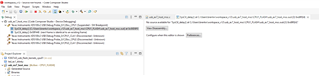
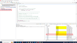
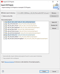
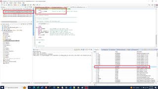
对于自定义引导加载程序、我使用 USB_EX7_HOST_Rev.c 工程开始 、该工程位于- C:\ti\c2000\C2000Ware_4_03_00_00\driverlib\f2837msc\examples\cpu1\usb、并合并了在- C:\ti\c2000\C2000Ware_4_03_00_00\libraries\boot_rom\f2837
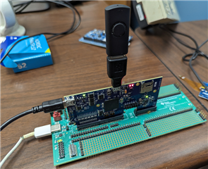
这样、我能够从闪存运行此应用。 我有一个 USB 闪存驱动器(笔式驱动器)、 上面有一个 led_ex1_blinky.dat 文件。 当我插入闪存驱动器时、从闪存运行的自定义引导加载程序 将读取 led_ex1_blinky.dat 文件并将其写入 RAM。 完成对 RAM 的写入后, 它将跳至 RAM 中的新 main()并开始正确执行(即 LED 开始闪烁)。 所以 、我认为我的自定义引导加载程序可以正常工作。
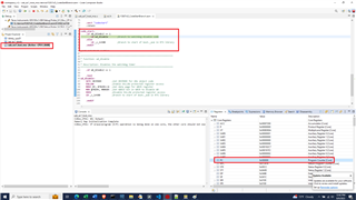
对于自定义闪存内核、我从以下 USB 闪存内核开始- C:\ti\c2000\C2000Ware_4_03_00_00\device_support\f2837xd\examples\dual\F2837xD_USB_flash_kernels\cpu01。 我修改了包含 USB_EX7_host_msc.c 功能的文件。
接下来、我可以从 RAM 运行该应用。 我有一个 USB 闪存驱动器(笔式驱动器) 、 上面有一个 led_ex1_blinky.dat 文件。 当我插入闪存驱动器时、从 RAM 运行的自定义闪存内核会读取 led_ex1_blinky.dat 文件并将其写入闪存。 完成对闪存的写入后 ,它将跳转到闪存中的新 main()并开始正确执行(即 LED 开始闪烁)。 所以 、我认为我的自定义闪存内核正在工作。
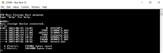
我遇到的问题是、当我尝试将两者合并时。 我首先从在闪存之外运行的自定义闪存引导加载程序开始。 我在 USB 闪存驱动器上有两个.dat 文件。 新的定制闪存内核和 led_ex1_blinky.dat。 此过程应模仿 USB 闪存编程器。
1)定制闪存引导加载程序在定制闪存内核.dat 文件中读取并将其写入 RAM
2)完成自定义闪存内核到 RAM 的写入后,它应该跳到 RAM 中的新的 main()并开始执行
3) 3)在执行自定义闪存内核期间、它应该在 led_ex1_blinky.dat 中读取并开始将其写入闪存
4)完成自定义闪存内核将 led_ex1_blinky.dat 映像写入闪存后,应跳转到闪存中的新 main()并开始执行
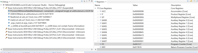
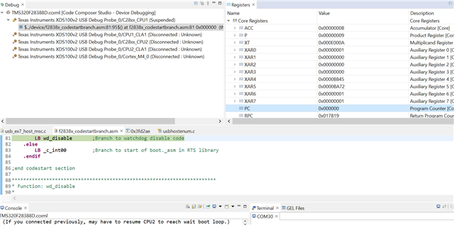
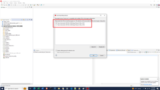
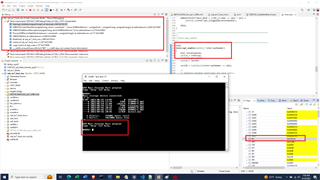
我看到了步骤1)和2)。 在新编程到 RAM 闪存内核开始执行后、即使已插接 USB、它也会等待 USB 枚举。 我不想拔下 USB 驱动器并将其重新插入以对 LED_ex1_blinky.dat 进行编程。
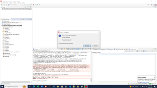
我的确尝试拔下 USB 驱动器并将其插回、此时它看起来已被检测到、但在 device.c 中出现故障-
void __error__(const char *filename, uint32_t line)
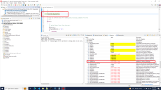
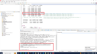
注意-在 RAM 中调试自定义闪存内核相当困难、因为此时全部是汇编语言(即、没有符号)。 通过此错误函数、我可以看到发生 assert 的文件:
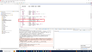
C:\ti\c2000\C2000Ware_4_03_00_00\libraries\communications\usc\f2837xd\source\host\usbhostenum.c。 具体而言、第5013行-
//*****************************************************************************
//
//! This function completes a control transaction to a device.
//!
//! \param ui32Index is the controller index to use for this transfer.
//! \param psSetupPacket is the setup request to be sent.
//! \param psDevice is the device instance pointer for this request.
//! \param pui8Data is the data to send for OUT requests or the receive buffer
//! for IN requests.
//! \param ui32Size is the size of the buffer in \e pui8Data.
//! \param ui32MaxPacketSize is the maximum packet size for the device for this
//! request.
//!
//! This function handles the state changes necessary to send a control
//! transaction to a device. This function should not be called from within
//! an interrupt callback as it is a blocking function.
//!
//! \return The number of bytes of data that were sent or received as a result
//! of this request.
//
//*****************************************************************************
uint32_t
USBHCDControlTransfer(uint32_t ui32Index, tUSBRequest *psSetupPacket,
tUSBHostDevice *psDevice, uint8_t *pui8Data,
uint32_t ui32Size, uint32_t ui32MaxPacketSize)
{
uint32_t ui32Remaining;
uint32_t ui32DataSize;
//
// Debug sanity check.
//
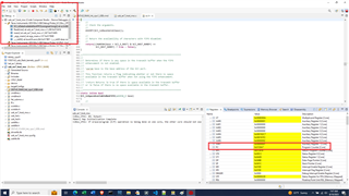
ASSERT(g_sUSBHEP0State.iState == eEP0StateIdle);
同样、由于我没有任何符号、因此只需汇编代码、就会使调试变得非常困难。
在自定义引导加载程序中、我尝试调用
SysCtl_resetPeripheral(SYSCTL_PERIPH_RES_USBA);
在自定义引导加载程序中 ,在跳转到闪存内核 main()以重置 USB 之前,自定义闪存内核会调用以下命令来初始化器件(包括 USB)注意,这主要来自 usb_ex7_host_msc.c:
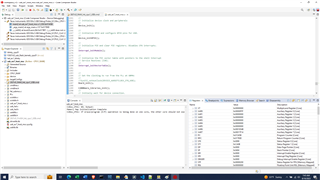
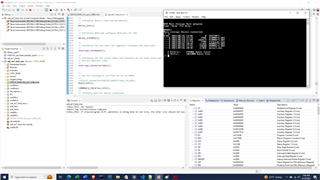
uint32_t main(void)
{
//
// Step 1. Initialize System Control:
// Enable Peripheral Clocks
// This example function is found in the F2837xD_SysCtrl.c file.
//
    InitSysCtrl(); //PLL activates
//
// Step 2. Initialize GPIO:
// This example function is found in the F2837xD_Gpio.c file and
// illustrates how to set the GPIO to it's default state.
//
    InitGpio();

//
// Step 3. Clear all interrupts and initialize PIE vector table:
// Disable CPU interrupts
//
    DINT;

//
// Initialize the PIE control registers to their default state.
// The default state is all PIE interrupts disabled and flags
// are cleared.
// This function is found in the F2837xD_PieCtrl.c file.
//
    InitPieCtrl();

//
// Disable CPU interrupts and clear all CPU interrupt flags:
//
    IER = 0x0000;
    IFR = 0x0000;

//
// Initialize the PIE vector table with pointers to the shell Interrupt
// Service Routines (ISR).
// This will populate the entire table, even if the interrupt
// is not used in this example.  This is useful for debug purposes.
// The shell ISR routines are found in F2837xD_DefaultIsr.c.
// This function is found in F2837xD_PieVect.c.
//
    InitPieVectTable();
    InitFlash();

//
// Gain pump semaphore
//

    SeizeFlashPump();

    Init_Flash_Sectors();

    Board_init();

    C2000Ware_libraries_init();

    EINT;
    ERTM;

    Interrupt_enableMaster();

    UsbHost_Initialize();
其中 Usb Host_Initialize () 是(基本上来自 usb_ex7_host_msc.c 中的 main ())
void UsbHost_Initialize()
{
    g_UsbRxBuffer = &g_cTmpBuf[0];
    startAddress = g_UsbRxBuffer;

    // initially wait for device connection.
    g_eState = STATE_NO_DEVICE;
    g_eUIState = STATE_NO_DEVICE;

    // configure the required pins for USB operation.
    USBGPIOEnable();

    // register the interrupt handler for USB Interrupts.
    //Interrupt_register(INT_USBA, INT_myUSB0_ISR);

    // Initialize the USB stack mode and pass in a mode callback.
    //USBStackModeSet(0, eUSBModeForceHost, ModeCallback);

    // Register the host class drivers.
    USBHCDRegisterDrivers(0, g_ppHostClassDrivers, NUM_CLASS_DRIVERS);

    // Open an instance of the mass storage class driver.
    g_psMSCInstance = USBHMSCDriveOpen(0, (tUSBHMSCCallback)MSCCallback);

    // initialize the power configuration. This sets the power enable signal
    // to be active high and does not enable the power fault.
    //USBHCDPowerConfigInit(0, USBHCD_VBUS_AUTO_HIGH | USBHCD_VBUS_FILTER);

    // initialize the USB controller for OTG operation with a 2ms polling
    // rate.
    //USBHCDInit(0,g_pHCDPool, HCD_MEMORY_SIZE);

    // initialize the file system.
    f_mount(0, &g_sFatFs);
}
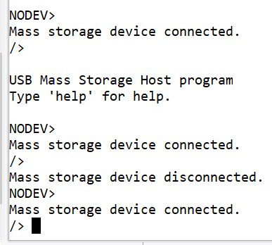
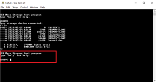
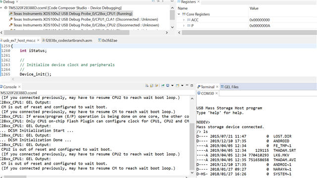
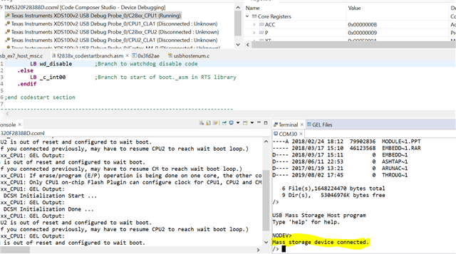
我有点卡在这一点上。 如果我从闪存运行自定义引导加载程序并将 led_ex1_blinky.dat 加载到 RAM 中、则是可行的。 如果我从 RAM 中运行自定义闪存内核并将 led_ex1_blinky.dat 加载到闪存中、则会起作用。 问题在于自定义引导加载程序何时加载自定义闪存内核。 在自定义闪存内核开始运行时、USB 未处于良好状态。 它不会枚举 USB (请参阅连接的 USB 闪存驱动器)、如果我将其拔下并重新插入、则会出现错误。
关键在于、在自定义引导加载程序对 USB 进行编程之后、运行闪存内核时它未处于良好状态(已初始化/已配置)。
当我离开自定义引导加载程序、转而在自定义闪存内核中初始化 USB 时、对 USB 进行复位/初始化/配置有什么想法吗?
我可以尝试或查看哪些内容?
感谢您的帮助。
布伦特