This thread has been locked.

If you have a related question, please click the "Ask a related question" button in the top right corner. The newly created question will be automatically linked to this question.

[参考译文] TMDSCNCD28379D:通过 USB 闪存驱动器(笔式驱动器)进行 USB 固件更新

Guru**** 665180 points
Other Parts Discussed in Thread: C2000WARE, TMDSCNCD28379D, TMDSCNCD28388D, TMS320F28379D
请注意,本文内容源自机器翻译,可能存在语法或其它翻译错误,仅供参考。如需获取准确内容,请参阅链接中的英语原文或自行翻译。

https://e2e.ti.com/support/microcontrollers/c2000-microcontrollers-group/c2000/f/c2000-microcontrollers-forum/1246300/tmdscncd28379d-usb-firmware-update-with-usb-flash-drive-pen-drive

器件型号:TMDSCNCD28379D
主题中讨论的其他器件:C2000WARE、、 TMDSCNCD28388DTMS320F28379D

作为 SDK 的一部分、TI 提供了一个 USB 闪存编程器- C:\ti\c2000\C2000Ware_4_03_00_00\utilities\flash_programmers\usb_flash_programmer。  

器件上的这个 USB 配置为器件模式、在该模式下、USB 主机是器件所连接的计算机。

我们希望能够通过插入 USB 闪存 驱动器(笔式驱动器)来执行固件更新。 为此、我认为需要自定义引导加载程序和自定义闪存内核。

对于自定义引导加载程序、我使用 USB_EX7_HOST_Rev.c 工程开始 、该工程位于- C:\ti\c2000\C2000Ware_4_03_00_00\driverlib\f2837msc\examples\cpu1\usb、并合并了在- C:\ti\c2000\C2000Ware_4_03_00_00\libraries\boot_rom\f2837

这样、我能够从闪存运行此应用。 我有一个 USB 闪存驱动器(笔式驱动器)、 上面有一个 led_ex1_blinky.dat 文件。 当我插入闪存驱动器时、从闪存运行的自定义引导加载程序  将读取 led_ex1_blinky.dat 文件并将其写入 RAM。 完成对 RAM 的写入后, 它将跳至 RAM 中的新 main()并开始正确执行(即 LED 开始闪烁)。 所以 、我认为我的自定义引导加载程序可以正常工作。

对于自定义闪存内核、我从以下 USB 闪存内核开始- C:\ti\c2000\C2000Ware_4_03_00_00\device_support\f2837xd\examples\dual\F2837xD_USB_flash_kernels\cpu01。 我修改了包含 USB_EX7_host_msc.c 功能的文件。   

接下来、我可以从 RAM 运行该应用。 我有一个 USB 闪存驱动器(笔式驱动器) 、  上面有一个 led_ex1_blinky.dat 文件。 当我插入闪存驱动器时、从 RAM 运行的自定义闪存内核会读取  led_ex1_blinky.dat 文件并将其写入闪存。 完成对闪存的写入后 ,它将跳转到闪存中的新 main()并开始正确执行(即 LED 开始闪烁)。 所以 、我认为我的自定义闪存内核正在工作。

我遇到的问题是、当我尝试将两者合并时。 我首先从在闪存之外运行的自定义闪存引导加载程序开始。 我在 USB 闪存驱动器上有两个.dat 文件。 新的定制闪存内核和  led_ex1_blinky.dat。 此过程应模仿 USB 闪存编程器。  

1)定制闪存引导加载程序在定制闪存内核.dat 文件中读取并将其写入 RAM

2)完成自定义闪存内核到 RAM 的写入后,它应该跳到 RAM 中的新的 main()并开始执行

3) 3)在执行自定义闪存内核期间、它应该在 led_ex1_blinky.dat 中读取并开始将其写入闪存

4)完成自定义闪存内核将 led_ex1_blinky.dat 映像写入闪存后,应跳转到闪存中的新 main()并开始执行

我看到了步骤1)和2)。 在新编程到 RAM 闪存内核开始执行后、即使已插接 USB、它也会等待 USB 枚举。 我不想拔下 USB 驱动器并将其重新插入以对 LED_ex1_blinky.dat 进行编程。  

我的确尝试拔下 USB 驱动器并将其插回、此时它看起来已被检测到、但在 device.c 中出现故障-  

void __error__(const char *filename, uint32_t line)

注意-在 RAM 中调试自定义闪存内核相当困难、因为此时全部是汇编语言(即、没有符号)。 通过此错误函数、我可以看到发生 assert 的文件:

C:\ti\c2000\C2000Ware_4_03_00_00\libraries\communications\usc\f2837xd\source\host\usbhostenum.c。 具体而言、第5013行-

//*****************************************************************************
//
//! This function completes a control transaction to a device.
//!
//! \param ui32Index is the controller index to use for this transfer.
//! \param psSetupPacket is the setup request to be sent.
//! \param psDevice is the device instance pointer for this request.
//! \param pui8Data is the data to send for OUT requests or the receive buffer
//! for IN requests.
//! \param ui32Size is the size of the buffer in \e pui8Data.
//! \param ui32MaxPacketSize is the maximum packet size for the device for this
//! request.
//!
//! This function handles the state changes necessary to send a control
//! transaction to a device.  This function should not be called from within
//! an interrupt callback as it is a blocking function.
//!
//! \return The number of bytes of data that were sent or received as a result
//! of this request.
//
//*****************************************************************************
uint32_t
USBHCDControlTransfer(uint32_t ui32Index, tUSBRequest *psSetupPacket,
                      tUSBHostDevice *psDevice, uint8_t *pui8Data,
                      uint32_t ui32Size, uint32_t ui32MaxPacketSize)
{
    uint32_t ui32Remaining;
    uint32_t ui32DataSize;

    //
    // Debug sanity check.
    //
    ASSERT(g_sUSBHEP0State.iState == eEP0StateIdle);

同样、由于我没有任何符号、因此只需汇编代码、就会使调试变得非常困难。

在自定义引导加载程序中、我尝试调用  

SysCtl_resetPeripheral(SYSCTL_PERIPH_RES_USBA); 

在自定义引导加载程序中 ,在跳转到闪存内核 main()以重置 USB 之前,自定义闪存内核会调用以下命令来初始化器件(包括 USB)注意,这主要来自  usb_ex7_host_msc.c

uint32_t main(void)
{
//
// Step 1. Initialize System Control:
// Enable Peripheral Clocks
// This example function is found in the F2837xD_SysCtrl.c file.
//
    InitSysCtrl(); //PLL activates
//
// Step 2. Initialize GPIO:
// This example function is found in the F2837xD_Gpio.c file and
// illustrates how to set the GPIO to it's default state.
//
    InitGpio();

//
// Step 3. Clear all interrupts and initialize PIE vector table:
// Disable CPU interrupts
//
    DINT;

//
// Initialize the PIE control registers to their default state.
// The default state is all PIE interrupts disabled and flags
// are cleared.
// This function is found in the F2837xD_PieCtrl.c file.
//
    InitPieCtrl();

//
// Disable CPU interrupts and clear all CPU interrupt flags:
//
    IER = 0x0000;
    IFR = 0x0000;

//
// Initialize the PIE vector table with pointers to the shell Interrupt
// Service Routines (ISR).
// This will populate the entire table, even if the interrupt
// is not used in this example.  This is useful for debug purposes.
// The shell ISR routines are found in F2837xD_DefaultIsr.c.
// This function is found in F2837xD_PieVect.c.
//
    InitPieVectTable();
    InitFlash();

//
// Gain pump semaphore
//

    SeizeFlashPump();

    Init_Flash_Sectors();

    Board_init();

    C2000Ware_libraries_init();

    EINT;
    ERTM;

    Interrupt_enableMaster();

    UsbHost_Initialize();

其中  Usb Host_Initialize () 是(基本上来自 usb_ex7_host_msc.c 中的 main ())

void UsbHost_Initialize()
{
    g_UsbRxBuffer = &g_cTmpBuf[0];
    startAddress = g_UsbRxBuffer;

    // initially wait for device connection.
    g_eState = STATE_NO_DEVICE;
    g_eUIState = STATE_NO_DEVICE;

    // configure the required pins for USB operation.
    USBGPIOEnable();

    // register the interrupt handler for USB Interrupts.
    //Interrupt_register(INT_USBA, INT_myUSB0_ISR);

    // Initialize the USB stack mode and pass in a mode callback.
    //USBStackModeSet(0, eUSBModeForceHost, ModeCallback);

    // Register the host class drivers.
    USBHCDRegisterDrivers(0, g_ppHostClassDrivers, NUM_CLASS_DRIVERS);

    // Open an instance of the mass storage class driver.
    g_psMSCInstance = USBHMSCDriveOpen(0, (tUSBHMSCCallback)MSCCallback);

    // initialize the power configuration. This sets the power enable signal
    // to be active high and does not enable the power fault.
    //USBHCDPowerConfigInit(0, USBHCD_VBUS_AUTO_HIGH | USBHCD_VBUS_FILTER);

    // initialize the USB controller for OTG operation with a 2ms polling
    // rate.
    //USBHCDInit(0,g_pHCDPool, HCD_MEMORY_SIZE);

    // initialize the file system.
    f_mount(0, &g_sFatFs);
}

我有点卡在这一点上。 如果我从闪存运行自定义引导加载程序并将  led_ex1_blinky.dat 加载到 RAM 中、则是可行的。 如果我从 RAM 中运行自定义闪存内核并将 led_ex1_blinky.dat 加载到闪存中、则会起作用。 问题在于自定义引导加载程序何时加载自定义闪存内核。 在自定义闪存内核开始运行时、USB 未处于良好状态。 它不会枚举 USB (请参阅连接的 USB 闪存驱动器)、如果我将其拔下并重新插入、则会出现错误。

关键在于、在自定义引导加载程序对 USB 进行编程之后、运行闪存内核时它未处于良好状态(已初始化/已配置)。

当我离开自定义引导加载程序、转而在自定义闪存内核中初始化 USB 时、对 USB 进行复位/初始化/配置有什么想法吗?

我可以尝试或查看哪些内容?

感谢您的帮助。

布伦特

  • 请注意,本文内容源自机器翻译,可能存在语法或其它翻译错误,仅供参考。如需获取准确内容,请参阅链接中的英语原文或自行翻译。

    Brent、

    如果在 自定义闪存引导加载程序 执行期间已检测到 USB、您需要再次枚举它吗?

    定制闪存引导加载程序是否等待再次枚举/检测 USB?

    此致

    西达尔特

  • 请注意,本文内容源自机器翻译,可能存在语法或其它翻译错误,仅供参考。如需获取准确内容,请参阅链接中的英语原文或自行翻译。

    尊敬的 Siddharth:

    感谢您的答复。 我想我想知道如何实现这一点吗?

    同样、对于自定义引导加载程序、我从  usb_ex7_host_msc.c 开始、加入了一些 USB 引导 ROM 代码- C:\ti\c2000\C2000Ware_4_03_00_00\libraries\boot_rom\f2837xd\revB\rom_source

    #include "board.h"
    #include "c2000ware_libraries.h"
    #include "usb_host.h"
    #include "c1_bootrom.h"
    
    //******************************************************************************
    //
    // This is the main loop that runs the application.
    //
    //******************************************************************************
    uint32_t main(void)
    {
        // initialize device clock and peripherals
        Device_init();
    
        // initialize GPIO and configure GPIO pins for USB.
        Device_initGPIO();
    
        // initialize PIE and clear PIE registers. Disables CPU interrupts.
        Interrupt_initModule();
    
        // initialize the PIE vector table with pointers to the shell Interrupt
        // Service Routines (ISR).
        Interrupt_initVectorTable();
    
        Board_init();
    
        C2000Ware_libraries_init();
    
        // enable Global Interrupt (INTM) and realtime interrupt (DBGM)
        EINT;
        ERTM;
    
        // enable interrupts
        Interrupt_enableMaster();
    
        UsbHost_Initialize();
    
        while(UsbHost_CheckForFlashDrive() == false)
        {
            SysCtl_delay(SysCtl_getClock(20000000U)/30);
        }
    
        numBytes = Cmd_Read_Firmware_Data(false);
    	
        uint32_t EntryAddr = USB_Boot(USB_BOOT);
        
    	UsbHost_CloseFile();
    
        return entryAddr;
    }


    这是我修改过的 USB_Boot ()。 您可以看到、它在结束时会执行以下操作(原始 代码的一部分):

    //从总线断开,禁用 USB 中断,并且
    //重置 USB 模块。 但首先、等待电池组上的任何
    //传输至完成。

    那么、 我不确定它如何保持枚举状态? 我的确尝试注释了该部分代码、但没有产生任何差异。

    Uint32 USB_Boot(Uint16 bootMode)
    {
        uint32_t disconnectDelay;
        entryAddr = FLASH_ENTRY_POINT;
    
    
        //Assign the USB data reader function to the global
        //function pointer for loading data.
        GetWordData = &USB_GetWordData;
    
        //The first data word should be a valid key. If it's not,
        //bypass the bootloader.
        if (USB_GetWordData() != 0x08AA)
            return FLASH_ENTRY_POINT;
    
        //Use the shared utility functions to load the data.
        ReadReservedFn();
        entryAddr = GetLongData();
        CopyData();
    	
        //Disconnect from the bus, disable USB interrupts, and
        //reset the USB module. But first, wait for any ongoing
        //transfers to complete.
        for (disconnectDelay = 0; disconnectDelay < 10000; disconnectDelay++) {;}
        USBREG8(USB_O_POWER) &= ~USB_POWER_SOFTCONN;
        EALLOW;
        PieCtrlRegs.PIEIER9.bit.INTx15 = 0;
        IER &= ~M_INT9;
        DevCfgRegs.SOFTPRES11.bit.USB_A = 1;
        DevCfgRegs.SOFTPRES11.bit.USB_A = 0;
        EDIS;
    
        //Bypass and disable the main and aux PLLs
        EALLOW;
        ClkCfgRegs.SYSPLLCTL1.bit.PLLCLKEN = 0;
        ClkCfgRegs.SYSPLLMULT.bit.IMULT = 0;
        ClkCfgRegs.SYSPLLCTL1.bit.PLLEN = 0;
        ClkCfgRegs.AUXPLLCTL1.bit.PLLCLKEN = 0;
        ClkCfgRegs.AUXPLLMULT.bit.IMULT = 0;
        ClkCfgRegs.AUXPLLCTL1.bit.PLLEN = 0;
        EDIS;
    
        return entryAddr;
    }

    下面是我的定制闪存内核代码。 回调  无效 MSCCallback (() 设置枚举状态并将其存储在  g_estate 中。 此回调在 Usb Host_Initialize ()中设置(此函数也将 g_estate 设置为默认状态)。

    g_psMSCInstance = USBHMSCDriveOpen(0, (tUSBHMSCCallback)MSCCallback);

    //*****************************************************************************
    //
    // USB Configurations
    //
    //*****************************************************************************
    //
    // Define to pass to SysCtl_setAuxClock(). Will configure the clock as follows:
    // AUXPLLCLK =
    //       20MHz (XTAL_OSC) * 12 (IMULT) / (4 (SYSDIV) )
    //
    #define DEVICE_AUXSETCLOCK_CFG_USB   (SYSCTL_OSCSRC_XTAL | SYSCTL_PLL_ENABLE |\
                                          SYSCTL_IMULT(12) | SYSCTL_SYSDIV(4))
    #define myUSB0_BASE USB0_BASE
    
    // Interrupt Settings for INT_myUSB0
    #define INT_myUSB0 INT_USBA
    #define INT_myUSB0_INTERRUPT_ACK_GROUP INTERRUPT_ACK_GROUP9
    extern __interrupt void INT_myUSB0_ISR(void);
    
    #define DEVICE_OSCSRC_FREQ          20000000U
    #define DEVICE_SYSCLK_FREQ          ((DEVICE_OSCSRC_FREQ * 20 * 1) / 2)
    #define DEVICE_GPIO_PIN_LED1        31U  // GPIO number for LD2
    #define DEVICE_DELAY_US(x) SysCtl_delay(((((long double)(x)) / (1000000.0L /  \
                                  (long double)DEVICE_SYSCLK_FREQ)) - 9.0L) / 5.0L)
    
    uint8_t g_pui8HCDPool[myUSB0_LIB_HCD_MEMORY_SIZE];
    
    
    // definitions
    bool flashDriveConnected = false;
    bool readFileContents = false;
    bool firstTime = false;
    
    volatile tState g_eState;
    volatile tState g_eUIState;
    extern char * g_UsbRxBuffer;
    char * startAddress;
    
    int numBytes;
    FRESULT fresult;
    
    int Cmd_Read_Firmware_Data(bool);
    
    //******************************************************************************
    //
    // The current USB operating mode - Host, Device or unknown.
    //
    //******************************************************************************
    tUSBMode g_eCurrentUSBMode;
    
    
    //******************************************************************************
    //
    // This buffer holds the full path to the current working directory.  Initially
    // it is root ("/").
    //
    //******************************************************************************
    static char g_cCwdBuf[PATH_BUF_SIZE] = "/";
    
    
    //******************************************************************************
    //
    // A temporary data buffer used when manipulating file paths, or reading data
    // from the memory card.
    //
    //******************************************************************************
    static char g_cTmpBuf[CMD_BUF_SIZE];
    
    
    //******************************************************************************
    //
    // The memory pool to provide to the Host controller driver.
    //
    //******************************************************************************
    //uint8_t g_pHCDPool[HCD_MEMORY_SIZE];
    
    
    //******************************************************************************
    //
    // The instance data for the MSC driver.
    //
    //******************************************************************************
    tUSBHMSCInstance *g_psMSCInstance = 0;
    
    
    //******************************************************************************
    //
    // Declare the USB Events driver interface.
    //
    //******************************************************************************
    DECLARE_EVENT_DRIVER(g_sUSBEventDriver, 0, 0, USBHCDEvents);
    
    
    //******************************************************************************
    //
    // The global that holds all of the host drivers in use in the application.
    // In this case, only the MSC class is loaded.
    //
    //******************************************************************************
    static tUSBHostClassDriver const * const g_ppHostClassDrivers[] =
    {
        &g_sUSBHostMSCClassDriver,
        &g_sUSBEventDriver
    };
    
    
    //******************************************************************************
    //
    // A table that holds a mapping between the numerical FRESULT code and
    // it's name as a string.  This is used for looking up error codes for
    // printing to the console.
    //
    //******************************************************************************
    tFresultString g_sFresultStrings[] =
    {
        FRESULT_ENTRY(FR_OK),
        FRESULT_ENTRY(FR_NOT_READY),
        FRESULT_ENTRY(FR_NO_FILE),
        FRESULT_ENTRY(FR_NO_PATH),
        FRESULT_ENTRY(FR_INVALID_NAME),
        FRESULT_ENTRY(FR_INVALID_DRIVE),
        FRESULT_ENTRY(FR_DENIED),
        FRESULT_ENTRY(FR_EXIST),
        FRESULT_ENTRY(FR_RW_ERROR),
        FRESULT_ENTRY(FR_WRITE_PROTECTED),
        FRESULT_ENTRY(FR_NOT_ENABLED),
        FRESULT_ENTRY(FR_NO_FILESYSTEM),
        FRESULT_ENTRY(FR_INVALID_OBJECT),
        FRESULT_ENTRY(FR_MKFS_ABORTED)
    };
    
    
    //******************************************************************************
    //
    // USB Mode callback
    //
    // \param ulIndex is the zero-based index of the USB controller making the
    //        callback.
    // \param eMode indicates the new operating mode.
    //
    // This function is called by the USB library whenever an OTG mode change
    // occurs and, if a connection has been made, informs us of whether we are to
    // operate as a host or device.
    //
    // \return None.
    //
    //******************************************************************************
    void ModeCallback(uint32_t ui32Index, tUSBMode eMode)
    {
        //
        // Save the new mode.
        //
    
        g_eCurrentUSBMode = eMode;
    }
    
    
    int Cmd_Read_Firmware_Data(bool opened)
    {
        unsigned short usBytesRead;
    
        if (!opened)
        {
            //
            // Do not attempt to do anything if there is not a drive attached.
            //
            if(g_eState != STATE_DEVICE_READY)
            {
              return(FR_NOT_READY);
            }
    
            strcpy(g_cTmpBuf, "/firmware.dat");
    
            //
            // Open the file for reading.
            //
            fresult = f_open(&g_sFileObject, g_cTmpBuf, FA_READ);
    
            //
            // If there was some problem opening the file, then return an error.
            //
            if(fresult != FR_OK)
            {
              return(fresult);
            }
        }
    
        //
        // Read a block of data from the file.  Read as much as can fit in the
        // temporary buffer
        //
        fresult = f_read(&g_sFileObject, g_cTmpBuf, sizeof(g_cTmpBuf),
                         &usBytesRead);
    
        //
        // If there was an error reading, then print a newline and return the
        // error to the user.
        //
        if(fresult != FR_OK)
        {
            return(fresult);
        }
    	
        //
        // Return number of bytes read
        //
        return(usBytesRead);
    }
    
    
    //******************************************************************************
    //
    // This is the callback from the MSC driver.
    //
    // \param ui32Instance is the driver instance which is needed when communicating
    // with the driver.
    // \param ui32Event is one of the events defined by the driver.
    // \param pvData is a pointer to data passed into the initial call to register
    // the callback.
    //
    // This function handles callback events from the MSC driver.  The only events
    // currently handled are the MSC_EVENT_OPEN and MSC_EVENT_CLOSE.  This allows
    // the main routine to know when an MSC device has been detected and
    // enumerated and when an MSC device has been removed from the system.
    //
    // \return Returns \e true on success or \e false on failure.
    //
    //******************************************************************************
    void MSCCallback(tUSBHMSCInstance *psMSCInstance, uint32_t ui32Event,
                void *pvEventData)
    {
        //
        // Determine the event.
        //
        switch(ui32Event)
        {
            //
            // Called when the device driver has successfully enumerated an MSC
            // device.
            //
            case MSC_EVENT_OPEN:
            {
                //
                // Proceed to the enumeration state.
                //
                g_eState = STATE_DEVICE_ENUM;
                break;
            }
    
            //
            // Called when the device driver has been unloaded due to error or
            // the device is no longer present.
            //
            case MSC_EVENT_CLOSE:
            {
                //
                // Go back to the "no device" state and wait for a new connection.
                //
                g_eState = STATE_NO_DEVICE;
    
                break;
            }
    
            default:
            {
                break;
            }
        }
    }
    
    
    //******************************************************************************
    //
    // This is the generic callback from host stack.
    //
    // \param pvData is actually a pointer to a tEventInfo structure.
    //
    // This function will be called to inform the application when a USB event has
    // occurred that is outside those related to the mass storage device.  At this
    // point this is used to detect unsupported devices being inserted and removed.
    // It is also used to inform the application when a power fault has occurred.
    // This function is required when the g_USBGenericEventDriver is included in
    // the host controller driver array that is passed in to the
    // USBHCDRegisterDrivers() function.
    //
    // \return None.
    //
    //******************************************************************************
    void USBHCDEvents(void *pvData)
    {
        tEventInfo *pEventInfo;
    
        //
        // Cast this pointer to its actual type.
        //
        pEventInfo = (tEventInfo *)pvData;
    
        switch(pEventInfo->ui32Event)
        {
            //
            // New keyboard detected.
            //
            case USB_EVENT_UNKNOWN_CONNECTED:
            {
                //
                // An unknown device was detected.
                //
                g_eState = STATE_UNKNOWN_DEVICE;
    
                break;
            }
    
            //
            // Keyboard has been unplugged.
            //
            case USB_EVENT_DISCONNECTED:
            {
                //
                // Unknown device has been removed.
                //
                g_eState = STATE_NO_DEVICE;
    
                break;
            }
    
            case USB_EVENT_POWER_FAULT:
            {
                //
                // No power means no device is present.
                //
                g_eState = STATE_POWER_FAULT;
    
                break;
            }
    
            default:
            {
                break;
            }
        }
    }
    
    
    //******************************************************************************
    //
    // This function reads text from a file. The USB host main function is called
    // throughout this process to keep USB alive and well.
    //
    //******************************************************************************
    void TryToMountUsbDrive(void)
    {
       tState eStateCopy;
    
       // See if a mass storage device has been enumerated.
       if(g_eState == STATE_DEVICE_ENUM)
       {
           // Take it easy on the Mass storage device if it is slow to
           // start up after connecting.
           if(USBHMSCDriveReady(g_psMSCInstance) != 0)
           {
               // Wait about 100ms before attempting to check if the
               // device is ready again.
               SysCtl_delay(SysCtl_getClock(DEVICE_OSCSRC_FREQ)/30);
    
               //break;
           }
    
           // Reset the working directory to the root.
           g_cCwdBuf[0] = '/';
           g_cCwdBuf[1] = '\0';
    
           // Attempt to open the directory.  Some drives take longer to
           // start up than others, and this may fail (even though the USB
           // device has enumerated) if it is still initializing.
           f_mount(0, &g_sFatFs);
           if(f_opendir(&g_sDirObject, g_cCwdBuf) == FR_OK)
           {
               //
               // The drive is fully ready, so move to that state.
               //
               g_eState = STATE_DEVICE_READY;
           }
       }
    
       // See if the state has changed.  We make a copy of g_eUIState to
       // prevent a compiler warning about undefined order of volatile
       // accesses.
       eStateCopy = g_eUIState;
       if(g_eState != eStateCopy)
       {
           //
           // Determine the new state.
           //
           switch(g_eState)
           {
               //
               // A previously connected device has been disconnected.
               //
               case STATE_NO_DEVICE:
               {
                   flashDriveConnected = false;
                   readFileContents = false;
                   firstTime = false;
                   GPIO_writePin(DEVICE_GPIO_PIN_LED2, 1);
                   break;
               }
    
               // A mass storage device is being enumerated.
               case STATE_DEVICE_ENUM:
               {
                   break;
               }
    
               // A mass storage device has been enumerated and initialized.
               case STATE_DEVICE_READY:
               {
                   if (firstTime == false)
                   {
                       firstTime = true;
                       flashDriveConnected = true;
                       GPIO_writePin(DEVICE_GPIO_PIN_LED2, 0);
                       // Save the current state.
                       g_eUIState = g_eState;
                       return;
                   }
    
                   break;
               }
    
               // An unknown device has been connected.
               case STATE_UNKNOWN_DEVICE:
               {
                   break;
               }
    
               // A power fault has occurred.
    
               case STATE_POWER_FAULT:
               {
                   break;
               }
           }
    
           // Save the current state.
           g_eUIState = g_eState;
       }
    
       // Run the main routine of the Host controller driver.
       USBHCDMain();
    }
    
    
    void UsbHost_Initialize()
    {
        g_UsbRxBuffer = &g_cTmpBuf[0];
        startAddress = g_UsbRxBuffer;
    
        // initially wait for device connection.
        g_eState = STATE_NO_DEVICE;
        g_eUIState = STATE_NO_DEVICE;
    
        // configure the required pins for USB operation.
        USBGPIOEnable();
    
        // register the interrupt handler for USB Interrupts.
        //Interrupt_register(INT_USBA, INT_myUSB0_ISR);
    
        // Initialize the USB stack mode and pass in a mode callback.
        //USBStackModeSet(0, eUSBModeForceHost, ModeCallback);
    
        // Register the host class drivers.
        USBHCDRegisterDrivers(0, g_ppHostClassDrivers, NUM_CLASS_DRIVERS);
    
        // Open an instance of the mass storage class driver.
        g_psMSCInstance = USBHMSCDriveOpen(0, (tUSBHMSCCallback)MSCCallback);
    
        // initialize the power configuration. This sets the power enable signal
        // to be active high and does not enable the power fault.
        //USBHCDPowerConfigInit(0, USBHCD_VBUS_AUTO_HIGH | USBHCD_VBUS_FILTER);
    
        // initialize the USB controller for OTG operation with a 2ms polling
        // rate.
        //USBHCDInit(0,g_pHCDPool, HCD_MEMORY_SIZE);
    
        // initialize the file system.
        f_mount(0, &g_sFatFs);
    }
    
    void UsbHost_CloseFile()
    {
        f_close(&g_sFileObject);
    }
    
    
    bool UsbHost_CheckForFlashDrive()
    {
        TryToMountUsbDrive();
    
        if (flashDriveConnected == true && readFileContents == false)
        {
           readFileContents = true;
           return true;
        }
    
        return false;
    }
    
    
    //******************************************************************************
    //
    //! Host interrupt service routine wrapper to make ISR compatible with
    //! C2000 PIE controller.
    //
    //******************************************************************************
    __interrupt void
    INT_myUSB0_ISR(void)
    {
        USB0HostIntHandler();
        Interrupt_clearACKGroup(INTERRUPT_ACK_GROUP9);
    }
    
    
    //*****************************************************************************
    //
    // PINMUX Configurations
    //
    //*****************************************************************************
    void PinMux_init()
    {
        //
        // PinMux for modules assigned to CPU1
        //
    
        // USB pinmux
        GPIO_setAnalogMode(42, GPIO_ANALOG_ENABLED);
        GPIO_setAnalogMode(43, GPIO_ANALOG_ENABLED);
    
    }
    
    //*****************************************************************************
    //
    // INTERRUPT Configurations
    //
    //*****************************************************************************
    void INTERRUPT_init(){
    
        // Interrupt Settings for INT_myUSB0
        Interrupt_register(INT_myUSB0, &INT_myUSB0_ISR);
        Interrupt_enable(INT_myUSB0);
    }
    //*****************************************************************************
    //
    // USB Configurations
    //
    //*****************************************************************************
    void USB_init(){
        //
        // Set the clocking to run from the PLL at 60MHz
        //
        SysCtl_setAuxClock(DEVICE_AUXSETCLOCK_CFG_USB);
    }
    
    void USBLib_init(){
        //
        // Initialize the USB stack mode and pass in a mode callback.
        //
        USBStackModeSet(0, eUSBModeForceHost, ModeCallback);
        //
        // Initialize the power configuration.
        //
        USBHCDPowerConfigInit(0,USBHCD_VBUS_AUTO_HIGH | USBHCD_VBUS_FILTER);
        //
        // Initialize the USB controller for OTG operation with a 2ms polling
        // rate.
        //
        USBHCDInit(0,g_pui8HCDPool, myUSB0_LIB_HCD_MEMORY_SIZE);
    }
    
    void C2000Ware_libraries_init()
    {
        USBLib_init();
    }
    
    
    //*****************************************************************************
    //
    // Board Configurations
    // Initializes the rest of the modules.
    // Call this function in your application if you wish to do all module
    // initialization.
    // If you wish to not use some of the initializations, instead of the
    // Board_init use the individual Module_inits
    //
    //*****************************************************************************
    void Board_init()
    {
        EALLOW;
    
        PinMux_init();
        USB_init();
        INTERRUPT_init();
    
        EDIS;
    }
    
    extern Device_initGPIO();
    
    //
    // Main
    //
    uint32_t main(void)
    {
    //
    // Step 1. Initialize System Control:
    // Enable Peripheral Clocks
    // This example function is found in the F2837xD_SysCtrl.c file.
    //
        InitSysCtrl(); //PLL activates
    	
    //
    // Step 2. Initialize GPIO:
    // This example function is found in the F2837xD_Gpio.c file and
    // illustrates how to set the GPIO to it's default state.
    //
        InitGpio();
    
    //
    // Step 3. Clear all interrupts and initialize PIE vector table:
    // Disable CPU interrupts
    //
        DINT;
    
    //
    // Initialize the PIE control registers to their default state.
    // The default state is all PIE interrupts disabled and flags
    // are cleared.
    // This function is found in the F2837xD_PieCtrl.c file.
    //
        InitPieCtrl();
    
    //
    // Disable CPU interrupts and clear all CPU interrupt flags:
    //
        IER = 0x0000;
        IFR = 0x0000;
    
    //
    // Initialize the PIE vector table with pointers to the shell Interrupt
    // Service Routines (ISR).
    // This will populate the entire table, even if the interrupt
    // is not used in this example.  This is useful for debug purposes.
    // The shell ISR routines are found in F2837xD_DefaultIsr.c.
    // This function is found in F2837xD_PieVect.c.
    //
        InitPieVectTable();
        InitFlash();
    
    //
    // Gain pump semaphore
    //
        SeizeFlashPump();
    
        Init_Flash_Sectors();
    
        Board_init();
    
        C2000Ware_libraries_init();
    
    //
    // Enable Global Interrupt (INTM) and realtime interrupt (DBGM)
    //
        EINT;
        ERTM;
    
        Interrupt_enableMaster();
    	
    	UsbHost_Initialize();
    
        while(UsbHost_CheckForFlashDrive() == false)
        {
            SysCtl_delay(SysCtl_getClock(20000000U)/30);
        }
    
    //
    // Loads CPU01 application into FLASH
    //
        numBytes = Cmd_Read_Firmware_Data(false);
        uint32_t EntryAddr = USB_Boot(USB_BOOT);
        UsbHost_CloseFile();
    
    //
    // Leave control over flash pump
    //
        ReleaseFlashPump();
    
        return EntryAddr;
    }
    
    //
    // Init_Flash_Sectors - Initialize flash API and active flash bank sectors
    //
    void Init_Flash_Sectors(void)
    {
        EALLOW;
        Flash0EccRegs.ECC_ENABLE.bit.ENABLE = 0x0;
        Fapi_StatusType oReturnCheck;
    
        oReturnCheck = Fapi_initializeAPI(F021_CPU0_BASE_ADDRESS, 150);
    
        if(oReturnCheck != Fapi_Status_Success)
        {
            Example_Error(oReturnCheck);
        }
    
        oReturnCheck = Fapi_setActiveFlashBank(Fapi_FlashBank0);
    
        if(oReturnCheck != Fapi_Status_Success)
        {
            Example_Error(oReturnCheck);
        }
    
        Flash0EccRegs.ECC_ENABLE.bit.ENABLE = 0xA;
        EDIS;
    }
    
    //
    // assignSharedRAMstoCPU2 - Assign shared RAM to CPU2 control
    //
    
    //
    // Example_Error - For this example, if an error is found just stop here
    //
    #ifdef __TI_COMPILER_VERSION__
        #if __TI_COMPILER_VERSION__ >= 15009000
            #pragma CODE_SECTION(Example_Error,".TI.ramfunc");
        #else
            #pragma CODE_SECTION(Example_Error,"ramfuncs");
        #endif
    #endif
    void Example_Error(Fapi_StatusType status)
    {
        //
        // Error code will be in the status parameter
        //
        __asm("    ESTOP0");
    }

    当自定义引导加载程序跳转到自定义闪存内核代码并开始执行时、 USB 未正确初始化、否则它会枚举并开始在 LED 闪烁.dat 文件中读取数据。

    在查看我的自定义闪存内核代码时、您是否看到我在从自定义引导加载程序跳转到闪存内核后在初始化中没有执行或操作错误?

    同样、如果我使用在闪存之外运行的客户引导加载程序、让它在 RAM 中对 LED 闪烁程序进行编程、然后跳转到该程序即可。 这意味着自定义引导加载程序使用 LED 闪烁.dat 文件对 RAM 进行编程、并跳转到 LED 闪烁程序正确执行的位置并开始使 LED 闪烁。

    但在自定义引导加载程序将自定义闪存内核编程到 RAM 并开始执行后- USB 未处于良好状态。 在自定义引导加载程序对自定义闪存内核进行编程并跳转到此模式后、闪存内核代码仍位于 while 循环中:

        while(UsbHost_CheckForFlashDrive() == false)
        {
            SysCtl_delay(SysCtl_getClock(20000000U)/30);
        }
    

    如果我拔下并重新插回 USB 闪存驱动器、这就是我得到枚举错误的时候。 所以、我不知道如何在闪存内核代码中正确地初始化 USB?

    我想在将自定义闪存内核编程到 RAM 后、不必拔下 USB 闪存驱动器。 不确定怎么做?

    我有一段时间一直在研究这个。 非常感谢您提供任何帮助或建议。

    谢谢。

    布伦特

  • 请注意,本文内容源自机器翻译,可能存在语法或其它翻译错误,仅供参考。如需获取准确内容,请参阅链接中的英语原文或自行翻译。

    以便提供更多信息。 我从闪存运行自定义引导加载程序、而没有下载、编程和执行自定义闪存内核。 我下载、编程并执行 USB_EX7_HOST_msc 应用程序、以查看是否可以正常工作(闪烁 LED 程序可以正常工作)。

    结果是、我得到相同的误差。

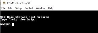
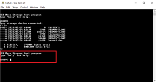
    自定义 USB 主机引导加载程序能够读取  usb_ex7_host_msc.dat 文件并将其写入 RAM、 USB_EX7_HOST_msc 应用程序将开始执行该文件。  usb_ex7_host_msc 将按预期在终端窗口中显示以下内容:

    在这一点上、它将调用 读数线()

    while(1)
    {
    //
    // Get a line of text from the user.
    //
       ReadLine(); <== NEVER RETURNS FROM

    在 ReadLine()中,  g_遗产 从不更改为  状态设备枚举 。 这将发生在回调函数中、  MSCCallback() 但绝不会这样。

    如果我拔下插入的 USB 闪存驱动器再插回、就 会得到上面描述的枚举错误。

    底线是 USB_EX7_HOST_msc 应用程序(以及我的自定义闪存内核)未 正确初始化 USB。

    我开始了解 USB 闪存内核如何初始化 USB。 请注意、它用于 USB 设备模式、而不是主机模式、这是我所需要的。

    查看 SDK 中 USB 闪存内核的代码- C:\ti\c2000\C2000Ware_4_03_00_00\device_support\f2837xd\examples\dual\F2837xD_USB_flash_kernels\cpu01

    在  F2837xD_USB_FLASH_kernels_cpu01.c -  USB_Boot () 被调用。


    uint32_t EntryAddr = USB_Boot(USB_BOOT);

    USB_引导( )它呼叫  USB_Init () 执行以下操作来配置 USB 器件  模式:

    //
    // USB_Init -  Jump starts some vital set-up for USB protocol.
    //
    void USB_Init()
    {
        //
        //enable USB controller clock
        //initialize three layers of interrupt enables
        //peripheral interrupt, PIE interrupt, EINT/DINT
        //
        EALLOW;
        //ClkCfgRegs.CLKSRCCTL1.bit.OSCCLKSRCSEL = 0x0;    //Use INTOSC2 (~10 MHz)
                                                           //as the main PLL
                                                           //clock source
        ClkCfgRegs.SYSPLLMULT.all = 12;                    //Set IMULT to 12,
                                                           //clear FMULT
        ClkCfgRegs.SYSPLLCTL1.bit.PLLEN = 1;               //Enable the main PLL
        ClkCfgRegs.SYSCLKDIVSEL.bit.PLLSYSCLKDIV = 0;      //Set PLLSYSCLKDIV to 1
        while (ClkCfgRegs.SYSPLLSTS.bit.LOCKS != 1) {;}    //Wait for the PLL to
                                                           //lock
        ClkCfgRegs.SYSPLLCTL1.bit.PLLCLKEN = 1;            //Turn off the main
                                                           //PLL bypass
    
        //ClkCfgRegs.CLKSRCCTL2.bit.AUXOSCCLKSRCSEL = 0x1; //Use XTAL (20 MHz) as
                                                           //the aux PLL clock
                                                           //source
        ClkCfgRegs.AUXPLLMULT.all = 6;                     //Set IMULT to 6, clear
                                                           //FMULT - 120MHz
        ClkCfgRegs.AUXPLLCTL1.bit.PLLEN = 1;               //Enable the aux PLL
        ClkCfgRegs.AUXCLKDIVSEL.bit.AUXPLLDIV = 2/2;       //Set AUXPLLDIV to 2
        while (ClkCfgRegs.AUXPLLSTS.bit.LOCKS != 1) {;}    //Wait for the PLL
                                                           //to lock
        ClkCfgRegs.AUXPLLCTL1.bit.PLLCLKEN = 1;            //Turn off aux PLL
                                                           //bypass
        DevCfgRegs.DC12.bit.USB_A = 1;     //feature enabled: device only
        CpuSysRegs.PCLKCR11.bit.USB_A = 1; //module clock turned on
    
        //
        //Connect the PHY to the GPIO pins by setting the GPBAMSEL
        //bits for GPIOs 42 and 43. VBUS and ID are now de-spec'd
        //due to the lack of a 5V fail-safe ESD structure, so
        //GPIOs 46 and 47 are not muxed out.
        //
        GpioCtrlRegs.GPBAMSEL.bit.GPIO42 = 1;
        GpioCtrlRegs.GPBAMSEL.bit.GPIO43 = 1;
    
        IER = 0x0000;
        IFR = 0x0000;
        //c1brom_enable_pie_in_boot(0);
        PieVectTable.USBA_INT = &UsbIntHandler;
        PieCtrlRegs.PIECTRL.bit.ENPIE = 1;  //enable the PIE block
        PieCtrlRegs.PIEIER9.bit.INTx15 = 1; //enable USBA interrupt(CPU1 only)
        EDIS;
        IER |= M_INT9;
        EINT;
    
        //
        //Reset the USB driver's global variables
        //
        ResetUsbDriver();
    
        //
        //Force USB device mode by setting DEVMODOTG and DEVMOD
        //
        USBREG32(USB_O_GPCS) = 0x3;
    
        //
        //Clear active interrupts
        //
        USBREG16(USB_O_TXIS);
        USBREG16(USB_O_RXIS);
        USBREG8(USB_O_IS);
    
        //
        //Set up endpoint 1 for bulk transfers with a 64-byte FIFO
        //
        USBREG8(USB_O_EPIDX) = 1;
        USBREG8(USB_O_RXFIFOSZ) = 0x03;
        USBREG16(USB_O_RXFIFOADD) = 0x100;
        USBREG8(USB_O_RXCSRH1) = 0x40;
    
        //
        //Enable USB interrupts for EP0 transmit/receive, EP1 receive,
        //disconnection, and reset
        //
        USBREG16(USB_O_TXIE) = 0x0001;
        USBREG16(USB_O_RXIE) = 0x0002;
        USBREG8(USB_O_IE) = (USB_IE_DISCON | USB_IE_RESET);
    
        //
        //Attach the USB PHY to the bus
        //
        USBREG8(USB_O_POWER) |= USB_POWER_SOFTCONN;
    }

     usb_ex7_host_msc 应用程序将执行以下操作来初始化 USB 主机  模式:

    void USB_init(){
        //
        // Set the clocking to run from the PLL at 60MHz
        //
        SysCtl_setAuxClock(DEVICE_AUXSETCLOCK_CFG_USB);
    }
    
    
    //*****************************************************************************
    //
    // PINMUX Configurations
    //
    //*****************************************************************************
    void PinMux_init()
    {
    	//
    	// PinMux for modules assigned to CPU1
    	//
    	
    	// USB pinmux
    	GPIO_setAnalogMode(42, GPIO_ANALOG_ENABLED);
    	GPIO_setAnalogMode(43, GPIO_ANALOG_ENABLED);
    
    }
    
    
    void Board_init()
    {
    	EALLOW;
    
    	PinMux_init();
    	USB_init();
    	INTERRUPT_init();
    
    	EDIS;
    }
    
    
    uint8_t g_pui8HCDPool[myUSB0_LIB_HCD_MEMORY_SIZE];
    void USBLib_init(){
        //
        // Initialize the USB stack mode and pass in a mode callback.
        //
        USBStackModeSet(0, eUSBModeForceHost, ModeCallback);
        //
        // Initialize the power configuration.
        //
        USBHCDPowerConfigInit(0,USBHCD_VBUS_AUTO_HIGH | USBHCD_VBUS_FILTER);
        //
        // Initialize the USB controller for OTG operation with a 2ms polling
        // rate.
        //
        USBHCDInit(0,g_pui8HCDPool, myUSB0_LIB_HCD_MEMORY_SIZE);
    }
    
    
    void C2000Ware_libraries_init()
    {
        USBLib_init();
    }
    
    
    //******************************************************************************
    //
    //! Enables USB related GPIOs to perform their USB function.
    //
    //******************************************************************************
    void USBGPIOEnable(void)
    {
        //
        // Set the USB DM and DP.
        //
        GPIO_setMasterCore(42, GPIO_CORE_CPU1);
        GPIO_setAnalogMode(42, GPIO_ANALOG_ENABLED);
        GPIO_setMasterCore(43, GPIO_CORE_CPU1);
        GPIO_setAnalogMode(43, GPIO_ANALOG_ENABLED);
    
        //
        // Set the direction for VBUS.
        //
        GPIO_setMasterCore(46, GPIO_CORE_CPU1);
        GPIO_setDirectionMode(46, GPIO_DIR_MODE_IN);
    
        //
        // Set the direction for ID.
        //
        GPIO_setMasterCore(47, GPIO_CORE_CPU1);
        GPIO_setDirectionMode(47, GPIO_DIR_MODE_IN);
    
        GPIO_setMasterCore(120, GPIO_CORE_CPU1);
        GPIO_setDirectionMode(120, GPIO_DIR_MODE_IN);
    
        GPIO_setMasterCore(121, GPIO_CORE_CPU1);
    	GPIO_setDirectionMode(121, GPIO_DIR_MODE_OUT);
    	GPIO_writePin(121, 1);
    }
    
    
    int main(void)
    {
        int iStatus;
    
        //
        // Initialize device clock and peripherals
        //
        Device_init();
    
        //
        // Initialize GPIO and configure GPIO pins for USB.
        //
        Device_initGPIO();
    
        //
        // Initialize PIE and clear PIE registers. Disables CPU interrupts.
        //
        Interrupt_initModule();
    
        //
        // Initialize the PIE vector table with pointers to the shell Interrupt
        // Service Routines (ISR).
        //
        Interrupt_initVectorTable();
    
    
        //
        // Set the clocking to run from the PLL at 60MHz
        //
        //SysCtl_setAuxClock(DEVICE_AUXSETCLOCK_CFG_USB);
        Board_init();
    
        C2000Ware_libraries_init();
        //
        // Initially wait for device connection.
        //
        g_eState = STATE_NO_DEVICE;
        g_eUIState = STATE_NO_DEVICE;
    
        //
        // Enable Global Interrupt (INTM) and realtime interrupt (DBGM)
        //
        EINT;
        ERTM;
    
        //
        // Configure the required pins for USB operation.
        //
        USBGPIOEnable();
    
        //
        // Register the interrupt handler for USB Interrupts.
        //
        //Interrupt_register(INT_USBA, INT_myUSB0_ISR);
    
        //
        // Configure SCIA for debug output.
        //
        ConfigureSCI();
    
        SCIprintf("\n\nUSB Mass Storage Host program\n");
        SCIprintf("Type \'help\' for help.\n\n");
    
        //
        // Enable Interrupts
        //
        Interrupt_enableMaster();
    
        //
        // Initialize the USB stack mode and pass in a mode callback.
        //
        //USBStackModeSet(0, eUSBModeForceHost, ModeCallback);
    
        //
        // Register the host class drivers.
        //
        USBHCDRegisterDrivers(0, g_ppHostClassDrivers, NUM_CLASS_DRIVERS);
    
        //
        // Open an instance of the mass storage class driver.
        //
        g_psMSCInstance = USBHMSCDriveOpen(0, (tUSBHMSCCallback)MSCCallback);
    
    
        //
        // Initialize the power configuration. This sets the power enable signal
        // to be active high and does not enable the power fault.
        //
        //USBHCDPowerConfigInit(0, USBHCD_VBUS_AUTO_HIGH | USBHCD_VBUS_FILTER);
    
        //
        // Initialize the USB controller for OTG operation with a 2ms polling
        // rate.
        //
        //USBHCDInit(0,g_pHCDPool, HCD_MEMORY_SIZE);
    
        //
        // Initialize the file system.
        //
        f_mount(0, &g_sFatFs);
    

    也就是说、当自定义引导加载程序将执行移交给   在 RAM 中运行的 USB_EX7_HOST_msc 应用程序时、USB 闪存驱动器仍处于插入状态、但该应用程序从未被枚举。 如果我拔下 USB 闪存驱动器并重新将其插入进行枚举、 则会出现前面所述的错误。

    有人能提供一些见解吗、在主机模式下的 USB 的初始化/配置中、我需要做哪些不同的事情?  

    谢谢。

    布伦特

  • 请注意,本文内容源自机器翻译,可能存在语法或其它翻译错误,仅供参考。如需获取准确内容,请参阅链接中的英语原文或自行翻译。

    Brent、  

    将咨询引导 ROM 专家以了解他们是否对此有任何建议。  

    我们会在几天后回复您。

    此致

    西达尔特

  • 请注意,本文内容源自机器翻译,可能存在语法或其它翻译错误,仅供参考。如需获取准确内容,请参阅链接中的英语原文或自行翻译。

    尊敬的 Siddharth:

    我刚刚对此进行了跟进-关于需要如何为  usb_ex7_host_msc 应用程序更改 USB 初始化?

    步骤如下:

    1. 自定义引导加载程序在闪存之外运行
    2. 插入 USB 闪存驱动器(笔式驱动器)
    3. 自定义引导加载  程序从 USB 闪存驱动器(笔式驱动器)读取 USB_EX7_HOST_msc 应用程序中的数据
    4. 自定义引导加载程序将 USB_EX7_HOST_msc 应用程序写入 RAM
    5. 客户引导加载程序跳转到 RAM 中的 USB_EX7_HOST_msc 应用程序
    6. USB_EX7_HOST_msc 应用程序 开始执行
    7. USB 未在 USB_EX7_HOST_msc 应用程序中正确初始化
    8. 如果仍插入的 USB 闪存驱动器(画笔驱动器)未枚举(请注意、在 USB_EX7_HOST_msc 应用程序的 main ()中、它会设置 g_Estate = State_no_device;g_eUState = State_no_device;)。 如果我拔下并重新插入 USB 闪存驱动器、枚举会失败、如上所述。

    感谢您的帮助。

    布伦特

  • 请注意,本文内容源自机器翻译,可能存在语法或其它翻译错误,仅供参考。如需获取准确内容,请参阅链接中的英语原文或自行翻译。

    Brent、  

    我已经厌倦了从 RAM 运行"usb_ex7_host_msc"应用程序了、它可以检测到连接到它的闪存驱动器。  

    它在两种情况下都有效-当闪存驱动器已连接时、以及在代码开始执行后连接闪存驱动器时。  

    我也尝试了插拔闪存驱动器,它能够检测到的变化。  

    您能否尝试仅 从 RAM 运行 USB_EX7_HOST_msc 应用程序?

    此致

    西达尔特

  • 请注意,本文内容源自机器翻译,可能存在语法或其它翻译错误,仅供参考。如需获取准确内容,请参阅链接中的英语原文或自行翻译。

    尊敬的 Siddharth

    感谢您的答复。

    我可能没有正确解释我的问题。 我可以 在 CC 中启动 USB_EX7_HOST_msc 应用程序、并从 RAM 和闪存中运行该应用程序。 这不是我的问题。 我的问题是另一个用例。

    具体而言、 我们希望使用 USB 闪存驱动器(笔式驱动器)执行 USB 闪存编程。 此设备使用 USB 主机 测试模式。

    目前的闪存编程器使用 USB 器件 测试模式。 其工作原理如下:

    1. 处理器 在 ROM (USB 器件模式)中运行 USB 引导加载程序。
    2. 用户将 USB 连接到计算机并 进行枚举。
    3. 用户可以从命令行使用闪存内核和将编程到闪存的应用程序的参数运行 usb_flash_programr.exe。
    4. USB 引导加载程序会读取闪存内核并将其写入 RAM。
    5. 在 USB 引导加载程序完成将其写入 RAM 后、它将跳转到 RAM 中的闪存内核、然后开始执行。
    6. 在器件模式下使用 USB 的闪存内核读取应用程序并将应用程序写入闪存。
    7. 将应用程序写入闪存后、它将跳转至闪存并开始执行程序。

    为了在 USB 主机模式下使用 USB 闪存驱动器开始执行此过程、我创建了一个自定义引导加载程序。  对于自定义引导加载程序、我使用 USB_EX7_HOST_Revproject 启动、 该工程位于- C:\ti\cc2000\C2000Ware_4_03_00_00\driverlib\f2837xd\examples\cpu1\usb、并加入了在- C:\ti\c2000\c2000\C2000Ware_4_03_00_00\libraries\boot_rom\f2837xd\rom\f2837xd\

    此自定义引导加载程序在闪存外运行,并将从插入的 USB 闪存驱动器(笔式驱动器)中读取.dat 文件。 自定义引导加载程序会将.dat 文件写入 RAM。 一旦完成将.dat 文件写入 RAM 后、它将跳转至 RAM 并开始执行.at 程序。

    我已经对此进行了测试、其中.dat 文件是 LED 闪烁程序。 自定义引导加载程序将成功读取 LED Blink .dat 程序、将其写入 RAM、跳转到 RAM、并开始在 RAM 中执行 LED 闪烁程序。

    下一步是根据 usb_ex7_host_msc 项目创建自定义闪存内核、该项目将从 USB 闪存驱动器(Pen 驱动器)中读取 LED 闪烁.dat 文件、然后将.dat 文件写入闪存。 完成后、自定义闪存内核将跳转至闪存、并开始执行 LED 闪烁应用。

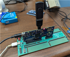
    第一步、我在主机模式下使用 USB 的自定义引导加载程序、并尝试 从 USB 闪存驱动器(笔式驱动器)中读取 USB_EX7_HOST_msc .dat 文件。 自定义 引导加载程序将读取 usb_ex7_host_msc .dat 文件并将.dat 文件写入 RAM。 完成后、它将跳转到 RAM 并开始执行。 注:USB 闪存驱动器(笔式驱动器)仍已插入。  RAM 中的 USB_EX7_HOST_msc 现在开始执行。

    已插入的 USB 闪存驱动器(笔式驱动器)不会重新进行枚举。 如果我拔下 USB 闪存驱动器(笔式驱动器)并将其重新插入、则会出现上述枚举错误。

    问题在于 USB_EX7_HOST_msc 项目初始化 USB 的当前方式在此用例中无法正常工作。 我需要修改、因为 USB_EX7_host_msc 项目 在主机模式下初始化 USB 的当前方式无法正常工作。

    明白了吗?

    对 USB_EX7_HOST_msc  项目中需要更改的内容有什么想法吗?

    感谢您的帮助。

    布伦特
  • 请注意,本文内容源自机器翻译,可能存在语法或其它翻译错误,仅供参考。如需获取准确内容,请参阅链接中的英语原文或自行翻译。

    Brent、

    我了解了用例。 如果  usb_ex7_host_msc 可以从 RAM 中工作、自定义引导加载程序复制后也可以工作。 您能否确保 已正确加载 USB_EX7_HOST_msc 的.dat 文件?  也许你可以使用 CCS 的内存浏览器来载入这个文件、看看它是否起作用。  

    另外、你可以通过检查 USBDEVCTL 寄存器来检查 USB 的模式?

    此致

    西达尔特  

  • 请注意,本文内容源自机器翻译,可能存在语法或其它翻译错误,仅供参考。如需获取准确内容,请参阅链接中的英语原文或自行翻译。

    尊敬的 Siddharth:

    自定义引导加载程序只使用 C:\ti\c2000\c2000\C2000Ware_4_03_00_00\libraries\boot_rom\f2837xd\revB\ROM_SOURCES USB_Boot ()。 我已经能够使用自定义引导加载程序、通过 LED Blink 程序等其他应用程序成功对 RAM 进行编程、没有任何问题。  

    在 CC 中、当 CC 将 USB_EX7_HOST_msc 应用程序加载到 RAM 中时、我对、text 段执行了内存转储;当自定义引导加载程序将 USB_EX7_HOST_msc 应用程序加载到 RAM 中时、我对.text 段执行了内存文本转储。

    它们是相同的。 这告诉我使用 C:\ti\c2000\C2000Ware_4_03_00_00\libraries\boot_rom\f2837xd\revB\ROM_SOURCES USB_Boot ()的自定义引导加载程序正在正确地对 RAM 进行编程。 我还使用 LED 闪烁程序重复了此过程。

    应用程序 usb_ex7_host_msc 应用程序.text 段从 0000c000开始、长度为00005f7c。 以下是存储器映射:

    ******************************************************************************
                 TMS320C2000 Linker PC v22.6.0                     
    ******************************************************************************
    >> Linked Wed Jul 19 10:25:37 2023
    
    OUTPUT FILE NAME:   <usb_ex7_host_msc.out>
    ENTRY POINT SYMBOL: "code_start"  address: 00000000
    
    
    MEMORY CONFIGURATION
    
             name            origin    length      used     unused   attr    fill
    ----------------------  --------  ---------  --------  --------  ----  --------
    PAGE 0:
      BEGIN                 00000000   00000002  00000002  00000000  RWIX
      RAMM0                 00000123   000002dd  00000090  0000024d  RWIX
      RAMLS0                00008000   00000800  00000000  00000800  RWIX
      RAMLS1                00008800   00000800  00000000  00000800  RWIX
      RAMLS2                00009000   00000800  00000000  00000800  RWIX
      RAMLS3                00009800   00000800  00000000  00000800  RWIX
      RAMLS4                0000a000   00000800  00000000  00000800  RWIX
      RAMD0                 0000b000   00000800  00000000  00000800  RWIX
      RAMGS0to7_combined    0000c000   00008000  00007644  000009bc  RWIX
      RESET                 003fffc0   00000002  00000000  00000002  RWIX
    
    PAGE 1:
      BOOT_RSVD             00000002   00000121  00000000  00000121  RWIX
      RAMM1                 00000400   000003f8  000003f8  00000000  RWIX
      RAMLS5                0000a800   00000800  00000000  00000800  RWIX
      RAMD1                 0000b800   00000800  00000000  00000800  RWIX
      RAMGS15_RSVD          0001bff8   00000008  00000000  00000008  RWIX
    
    
    SECTION ALLOCATION MAP
    
     output                                  attributes/
    section   page    origin      length       input sections
    --------  ----  ----------  ----------   ----------------
    codestart 
    *          0    00000000    00000002     
                      00000000    00000002     F2837xD_CodeStartBranch.obj (codestart)
    
    .cinit     0    00000128    0000008c     
                      00000128    00000078     (.cinit..data.load) [load image, compression = lzss]
                      000001a0    00000006     (__TI_handler_table)
                      000001a6    00000004     (.cinit..bss.load) [load image, compression = zero_init]
                      000001aa    00000002     --HOLE-- [fill = 0]
                      000001ac    00000008     (__TI_cinit_table)
    
    .text      0    0000c000    00005f7c     
      

    我已附加了两个存储器转储。

    e2e.ti.com/.../usb_5F00_ex7_5F00_host_5F00_msc_5F00_orig.dat

    e2e.ti.com/.../usb_5F00_ex7_5F00_host_5F00_msc_5F00_mine.dat

    您让我查看寄存器 USBDEVCTL。  我无法在 CC 中读取此寄存器与其他 USB 寄存器。 尝试将 USB 寄存器导出到文件时出现以下错误。 是否有其他方法可以获取此信息?

    C28xx_CPU1: Unable to save register UsbaRegs_USB_EPIDX_TEST: Memory map prevented reading 0x04000E@Program
    C28xx_CPU1: Unable to save register UsbaRegs_USBDEVCTL: Memory map prevented reading 0x040060@Program
    C28xx_CPU1: Unable to save register UsbaRegs_USB_TXFIFOSZ_RXFIFSZ: Memory map prevented reading 0x040062@Program
    C28xx_CPU1: Unable to save register UsbaRegs_USB_CONTIM_VPLEN: Memory map prevented reading 0x04007A@Program
    C28xx_CPU1: Unable to save register UsbaRegs_USBFSEOF: Memory map prevented reading 0x04007C@Program
    C28xx_CPU1: Unable to save register UsbaRegs_USBLSEOF: Memory map prevented reading 0x04007E@Program
    C28xx_CPU1: Unable to save register UsbaRegs_USBTXFUNCADDR0: Memory map prevented reading 0x040080@Program
    C28xx_CPU1: Unable to save register UsbaRegs_USB_TXHUBADDR0_TXHUBPORT0: Memory map prevented reading 0x040082@Program
    C28xx_CPU1: Unable to save register UsbaRegs_USBTXFUNCADDR1: Memory map prevented reading 0x040088@Program
    C28xx_CPU1: Unable to save register UsbaRegs_USB_TXHUBADDR1_TXHUBPORT1: Memory map prevented reading 0x04008A@Program
    C28xx_CPU1: Unable to save register UsbaRegs_USBRXFUNCADDR1: Memory map prevented reading 0x04008C@Program
    C28xx_CPU1: Unable to save register UsbaRegs_USB_RXHUBADDR1_RXHUBPORT1: Memory map prevented reading 0x04008E@Program
    C28xx_CPU1: Unable to save register UsbaRegs_USBTXFUNCADDR2: Memory map prevented reading 0x040090@Program
    C28xx_CPU1: Unable to save register UsbaRegs_USB_TXHUBADDR2_TXHUBPORT2: Memory map prevented reading 0x040092@Program
    C28xx_CPU1: Unable to save register UsbaRegs_USBRXFUNCADDR2: Memory map prevented reading 0x040094@Program
    C28xx_CPU1: Unable to save register UsbaRegs_USB_RXHUBADDR2_RXHUBPORT2: Memory map prevented reading 0x040096@Program
    C28xx_CPU1: Unable to save register UsbaRegs_USBTXFUNCADDR3: Memory map prevented reading 0x040098@Program
    C28xx_CPU1: Unable to save register UsbaRegs_USB_TXHUBADDR3_TXHUBPORT3: Memory map prevented reading 0x04009A@Program
    C28xx_CPU1: Unable to save register UsbaRegs_USBRXFUNCADDR3: Memory map prevented reading 0x04009C@Program
    C28xx_CPU1: Unable to save register UsbaRegs_USB_RXHUBADDR3_RXHUBPORT3: Memory map prevented reading 0x04009E@Program
    C28xx_CPU1: Unable to save register UsbaRegs_USB_CSRL0_CSRH0: Memory map prevented reading 0x040102@Program
    C28xx_CPU1: Unable to save register UsbaRegs_USBCOUNT0: Memory map prevented reading 0x040106@Program
    C28xx_CPU1: Unable to save register UsbaRegs_USB_TYPE0_NAKLMT: Memory map prevented reading 0x040108@Program
    C28xx_CPU1: Unable to save register UsbaRegs_USB_TXCSRL1_TXCSRH1: Memory map prevented reading 0x040112@Program
    C28xx_CPU1: Unable to save register UsbaRegs_USB_RXCSRL1_RXCSRH1: Memory map prevented reading 0x040116@Program
    C28xx_CPU1: Unable to save register UsbaRegs_USB_TXTYPE1_TXINTERVAL1: Memory map prevented reading 0x04011A@Program
    C28xx_CPU1: Unable to save register UsbaRegs_USB_RXTYPE1_RXINTERVAL1: Memory map prevented reading 0x04011C@Program
    C28xx_CPU1: Unable to save register UsbaRegs_USB_TXCSRL2_TXCSRH2: Memory map prevented reading 0x040122@Program
    C28xx_CPU1: Unable to save register UsbaRegs_USB_RXCSRL2_RXCSRH2: Memory map prevented reading 0x040126@Program
    C28xx_CPU1: Unable to save register UsbaRegs_USB_TXTYPE2_TXINTERVAL2: Memory map prevented reading 0x04012A@Program
    C28xx_CPU1: Unable to save register UsbaRegs_USB_RXTYPE2_RXINTERVAL2: Memory map prevented reading 0x04012C@Program
    C28xx_CPU1: Unable to save register UsbaRegs_USB_TXCSRL3_TXCSRH3: Memory map prevented reading 0x040132@Program
    C28xx_CPU1: Unable to save register UsbaRegs_USB_RXCSRL3_RXCSRH3: Memory map prevented reading 0x040136@Program
    C28xx_CPU1: Unable to save register UsbaRegs_USB_TXTYPE3_TXINTERVAL3: Memory map prevented reading 0x04013A@Program
    C28xx_CPU1: Unable to save register UsbaRegs_USB_RXTYPE3_RXINTERVAL3: Memory map prevented reading 0x04013C@Program

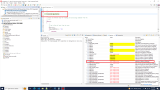
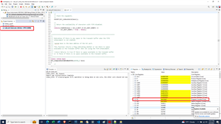
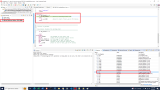
    以下是我在 CC 中看到的内容:

    我在 USB 被初始化后导出了 USB 寄存器。 出现此情况后、CC 会将 USB_EX7_HOST_msc 应用程序下载到 RAM 中。 我设置了一个断点 ,您可以在上面的图片中看到它调用 fmount()之前的断点。 另一个 USB 寄存器导出是在自定义引导加载程序将 USB_EX7_HOST_msc 应用程序编程到 RAM 中后完成的、该应用程序会跳转至该位置并开始执行。 我暂停执行并执行导出。

    e2e.ti.com/.../usb_5F00_ex7_5F00_host_5F00_msc.txt

    e2e.ti.com/.../usb_5F00_ex7_5F00_host_5F00_msc_5F00_written_5F00_into_5F00_ram_5F00_custom_5F00_bootloader.txt

     与使用自定义引导加载程序相比、在 CC 中下载和运行 USB_EX7_HOST_msc 应用程序存在差异。 自定义引导加载程序已将 USB 初始化/配置为主机模式、并且正在使用 USB 主机模式通过 USB_EX7_HOST_msc 应用程序对 RAM 进行编程 、然后再跳转到 USB_EX7_HOST_msc 应用程序并运行。  

    在这两种情况下、启动条件略有不同、在我看来、 USB_EX7_HOST_msc 应用程序在本例中似乎未正确地初始化/配置 USB 主机。

    您还提到了 使用 CC 的内存浏览器加载.dat 文件。 我了解如何进行导出、但不导入.dat 文件。 您能向我指出相关文档吗?

    希望这能提供一些见解。

    感谢您的帮助。

    布伦特

  • 请注意,本文内容源自机器翻译,可能存在语法或其它翻译错误,仅供参考。如需获取准确内容,请参阅链接中的英语原文或自行翻译。

    Brent、  

    USB Boot 将配置为设备模式、 USB_EX7_host_msc 将以主机模式运行。   USB_EX7_HOST_msc 无法处理 从设备模式切换到主机模式的这种用例。  还有一个示例(USB_EX8_dual_detect)、其从器件切换到主机模式。   在执行任何其他 USB 功能之前、您能否尝试在 usb_ex7_host_msc 中添加以下代码以重置 USB

    //
    //从总线断开,禁用 USB 中断,并且
    //重置 USB 模块。 但首先、等待电池组上的任何
    //传输至完成。
    //
    HWREGB (USB0_BASE + USB_O_POWER)&=~USB_POWER_SOFTCONN;

    //
    //禁用 USB 中断
    //
    interrupt_disable ((uint32_t) INT_USBA);

    //
    //重置 USB
    //
    SYSCTL_resetPeripheral (SYSCTL_Periph_RES_USBA);

    //
    //将 USB PHY 连接到总线
    //
    HWREGB (USB0_BASE + USB_O_POWER)|= USB_POWER_SOFTCONN;

    此致

    西达尔特

  • 请注意,本文内容源自机器翻译,可能存在语法或其它翻译错误,仅供参考。如需获取准确内容,请参阅链接中的英语原文或自行翻译。

    尊敬的  Siddharth:

    感谢您的答复。

    在自定义引导加载程序中,我从 USB_EX7_HOST_msc 应用程序开始,并添加了 USB_Boot ()代码。

    我注释掉了 USB_Boot ()中的 USB 初始化()调用,如下所示。

    我这样做是因为自定义引导加载程序(USB_EX7_HOST_msc 应用程序)在调用 USB_Boot ()时已配置为 USB 主机模式。 我想将其保持在 USB 主机模式、因为 USB_Boot ()正在 USB_EX7_HOST_msc 应用程序中读取 、以及使用 USB 主机模式写入 RAM。 我不想 为 USB 设备模式对其进行初始化。  

    所以, 我认为这不是问题所在。

    Uint32 USB_Boot(Uint16 bootMode)
    {
        uint32_t disconnectDelay;
        entryAddr = FLASH_ENTRY_POINT;
    
        //If the USB module is not enabled, bypass the bootloader
        //BAW if (DevCfgRegs.DC12.bit.USB_A == 0)
        //BAW    return FLASH_ENTRY_POINT;
    
        //Assign the USB data reader function to the global
        //function pointer for loading data.
        GetWordData = &USB_GetWordData;
    
        //Set up the USB to receive data
        // USB_Boot_Init();
        // UsbHost_Initialize();
    
        //BAW
        /*
        EntryAddr = TI_OTP_C1BROM_ESCAPE_POINT_13;
        if((EntryAddr != 0xFFFFFFFF) &&
                (EntryAddr != 0x00000000))
        {
            //if OTP is programmed, then call OTP function
            ((void (*)(void))EntryAddr)();
        }
        */
    
        //The first data word should be a valid key. If it's not,
        //bypass the bootloader.
        if (USB_GetWordData() != 0x08AA)
            return FLASH_ENTRY_POINT;
    
        //Use the shared utility functions to load the data.
        ReadReservedFn();
        entryAddr = GetLongData();
        CopyData();
    
        // BAW
        /*
        EntryAddr = TI_OTP_C1BROM_ESCAPE_POINT_13;
        if((EntryAddr != 0xFFFFFFFF) &&
                (EntryAddr != 0x00000000))
        {
            // if OTP is programmed, then call OTP function
            ((void (*)(void))EntryAddr)();
        }
        */
    
    #if 0
        //Disconnect from the bus, disable USB interrupts, and
        //reset the USB module. But first, wait for any ongoing
        //transfers to complete.
        for (disconnectDelay = 0; disconnectDelay < 10000; disconnectDelay++) {;}
        USBREG8(USB_O_POWER) &= ~USB_POWER_SOFTCONN;
        EALLOW;
        PieCtrlRegs.PIEIER9.bit.INTx15 = 0;
        IER &= ~M_INT9;
        DevCfgRegs.SOFTPRES11.bit.USB_A = 1;
        DevCfgRegs.SOFTPRES11.bit.USB_A = 0;
        EDIS;
    
        //Bypass and disable the main and aux PLLs
        EALLOW;
        ClkCfgRegs.SYSPLLCTL1.bit.PLLCLKEN = 0;
        ClkCfgRegs.SYSPLLMULT.bit.IMULT = 0;
        ClkCfgRegs.SYSPLLCTL1.bit.PLLEN = 0;
        ClkCfgRegs.AUXPLLCTL1.bit.PLLCLKEN = 0;
        ClkCfgRegs.AUXPLLMULT.bit.IMULT = 0;
        ClkCfgRegs.AUXPLLCTL1.bit.PLLEN = 0;
        EDIS;
    #endif
        // BAW
        /*
        EntryAddr = TI_OTP_C1BROM_ESCAPE_POINT_13;
        if((EntryAddr != 0xFFFFFFFF) &&
                (EntryAddr != 0x00000000))
        {
            // if OTP is programmed, then call OTP function
            ((void (*)(void))EntryAddr)();
        }
        */
    
    
        return entryAddr;
    }

    在自定义引导加载程序(USB_EX7_HOST_msc 应用程序)完成将 USB_EX7_HOST_msc 应用程序写入 RAM 后、我可以尝试添加上述代码 先前的 要跳转到 USB_EX7_HOST_msc 应用程序。

    "那你打算怎么办?"

    谢谢。

    布伦特

  • 请注意,本文内容源自机器翻译,可能存在语法或其它翻译错误,仅供参考。如需获取准确内容,请参阅链接中的英语原文或自行翻译。

    Brent、  

    您是在自定义引导加载程序中将其初始化为主机模式、还是在 usb_ex7_host_msc 应用程序中完成

    您可以尝试在  usb_ex7_host_msc 应用程序开始时添加上述代码。在开始运行 usb_ex7_host_msc 应用程序之前,该代码会确保 USB 已重置并且所有中断都已禁用。

    此致

    西达尔特

  • 请注意,本文内容源自机器翻译,可能存在语法或其它翻译错误,仅供参考。如需获取准确内容,请参阅链接中的英语原文或自行翻译。

    尊敬的  Siddharth:

    是的、 我要在自定义引导加载程序中针对主机模式初始化 USB。 同样、 自定义引导加载程序只是 USB_EX7_HOST_msc 应用程序、我在其中添加了 USB 引导代码。  自定义引导加载程序的 USB 初始化方式与 USB_EX7_HOST_msc 应用程序完全相同。

    自定义引导加载程序完成后、将 USB_EX7_HOST_msc 应用程序写入 RAM (自定义引导加载程序会通过 USB 主机(USB 闪存驱动器)读取该  应用程序)、它会跳转到 RAM 位置并开始执行 USB_EX7_HOST_msc 应用程序。  usb_ex7_host_msc 应用程序正在运行其 USB 主机初始化代码、但此时 USB 无法正常工作。

    我将尝试添加您在自定义引导加载程序完成后提供的代码  、将 USB_EX7_HOST_msc 应用程序写入到 RAM  、然后再跳转到 USB_EX7_HOST_msc 应用程序、在该应用程序中将进行 USB 主机初始化。

    布伦特

  • 请注意,本文内容源自机器翻译,可能存在语法或其它翻译错误,仅供参考。如需获取准确内容,请参阅链接中的英语原文或自行翻译。

    尊敬的  Siddharth:

    是的、 我要在自定义引导加载程序中针对主机模式初始化 USB。 同样、 自定义引导加载程序只是 USB_EX7_HOST_msc 应用程序、我在其中添加了 USB 引导代码。  自定义引导加载程序的 USB 初始化方式与 USB_EX7_HOST_msc 应用程序完全相同。

    自定义引导加载程序完成后、将 USB_EX7_HOST_msc 应用程序写入 RAM (自定义引导加载程序会通过 USB 主机(USB 闪存驱动器)读取该  应用程序)、它会跳转到 RAM 位置并开始执行 USB_EX7_HOST_msc 应用程序。  usb_ex7_host_msc 应用程序正在运行其 USB 主机初始化代码、但此时 USB 无法正常工作。

    我将尝试添加您在自定义引导加载程序完成后提供的代码  、将 USB_EX7_HOST_msc 应用程序写入到 RAM  、然后再跳转到 USB_EX7_HOST_msc 应用程序、在该应用程序中将进行 USB 主机初始化。

    我注意到在代码中显示的值高于 USB0_BASE。 您是指  

    #define USB0_BASE_ADDR  0x00040000 //在 USB_Regs.h 中找到 Soprano?

    布伦特

  • 请注意,本文内容源自机器翻译,可能存在语法或其它翻译错误,仅供参考。如需获取准确内容,请参阅链接中的英语原文或自行翻译。

    尊敬的 Siddharth:

    很遗憾、 我尝试了您上面提供的代码、但得到了相同的结果。

    我始终保持 USB 闪存驱动器(笔式驱动器)处于插入状态。

    1. 在 CC 中、从闪存运行客户引导加载程序。
    2. 自定义引导加载程序- USB 主机模式- 从 USB 闪存驱动器(笔式驱动器)读取 USB_EX7_HOST_msc 应用程序并将其编程到 RAM 中。
    3. 在跳至 RAM 并开始运行  usb_ex7_host_msc 应用程序后,将 USB 初始化为主机模式,并调用 ReadLine(),而它从此处返回。

     while(1)
        {
            //
            // Get a line of text from the user.
            //
            ReadLine();


       4.  ReadLine()中的 g_estate 从 State_no_device (值0)更改为 State_device_enum

       5.拔下 USB 闪存驱动器(笔式驱动器)并将其重新插入、CC 在以下位置停止:

    在映射文件0xd8F0中:

    0000d4e7 00000418 device.obj (.text)
    0000d8ff 00000376 usblib_eabi.lib:usbhostenum.obj (.text:USBHostIntHandlerInternal)

    我还附加了 USB 寄存器的5个捕获。 某些寄存器无法读取。 是否可以获取这些寄存器的内容?

    custom_bootloader_before_reset.txt - T 在调用您提供的代码之前、它是自定义引导加载程序中的 USB 寄存器。 它通过 USB_EX7_HOST_msc 应用程序对 RAM 进行了编程。

    custom_bootloader_after_reset.txt -这 是自定义引导加载程序应用程序中的 USB 寄存器、位于您提供的代码之后、跳转到 USB_EX7_host_msc 应用程序之前。

    usb_ex7_host_msc_fmount.txt - 这 是 usb_ex7_host_msc  应用程序中 f_mount ()处的 USB 寄存器。  

    usb_ex7_host_msc_after_fmount.txt -  这是 usb_ex7_host_msc 应用程序中的 USB 寄存器、在 f_mount ()后运行时将其暂停。 此时它卡在 ReadLine()中,没有枚举。

    usb_ex7_host_msc_unplug_plugin.txt - 这是 usb_ex7_host_msc 应用程序中的 USB 寄存器  在我拔下 USB 闪存驱动器并将其重新插入后。

    e2e.ti.com/.../custom_5F00_bootloader_5F00_before_5F00_reset.txt

    e2e.ti.com/.../custom_5F00_bootloader_5F00_after_5F00_reset.txt

    e2e.ti.com/.../usb_5F00_ex7_5F00_host_5F00_msc_5F00_fmount.txt

    e2e.ti.com/.../usb_5F00_ex7_5F00_host_5F00_msc_5F00_after_5F00_fmount.txt

    e2e.ti.com/.../usb_5F00_ex7_5F00_host_5F00_msc_5F00_unplug_5F00_plugin.txt

  • 请注意,本文内容源自机器翻译,可能存在语法或其它翻译错误,仅供参考。如需获取准确内容,请参阅链接中的英语原文或自行翻译。

    以便提供更多信息。

    由于 CC 寄存器视图不会显示某些 USB 寄存器、因此 我转至存储器窗口中的基址(0x40000)。   前面我们想知道 USBDEVCTL 的值(偏移量0x60)。  

    我   在 RAM 的 CC 中运行了 USB_EX7_HOST_msc 应用程序。 我在 f_mount()设置了一个断点。 该寄存器的值为0x5D。

    然后、我运行自定义引导加载程序、将 USB_EX7_HOST_msc 应用程序加载 到 RAM 中。 我在 f_mount()设置了一个断点。  USBDEVCTL 的值 也是0x5D。

    是否有其他需要值的寄存器?

    感谢您的帮助。

    布伦特

  • 请注意,本文内容源自机器翻译,可能存在语法或其它翻译错误,仅供参考。如需获取准确内容,请参阅链接中的英语原文或自行翻译。

    Brent、

    USBDEVCTL 的值0x5D 表示它处于主机模式。  要从  State_no_device 移至 State_device_enum,必须检测已连接的设备。 当 USB 信号发生变化并触发一个中断时、就会发生这种情况。   

    如果我 从 RAM 运行 usb_ex7_host_msc、然后连接/断开大容量存储设备、就可以检测到它、没有任何问题。  我不知道为什么在这种情况下无法检测到器件。   我们将看看您共享的寄存器转储、看看我是否找到了什么。

    此致

    西达尔特

  • 请注意,本文内容源自机器翻译,可能存在语法或其它翻译错误,仅供参考。如需获取准确内容,请参阅链接中的英语原文或自行翻译。

    谢谢 Siddharth

    如果有寄存器 、您希望该值不出现在寄存器转储中、而是出现在存储器视图中、请告知我。

    布伦特

  • 请注意,本文内容源自机器翻译,可能存在语法或其它翻译错误,仅供参考。如需获取准确内容,请参阅链接中的英语原文或自行翻译。

    Brent、  

    当然可以、我们将进行探讨、并为您提供解决此问题的任何建议。

    此致

    西达尔特

  • 请注意,本文内容源自机器翻译,可能存在语法或其它翻译错误,仅供参考。如需获取准确内容,请参阅链接中的英语原文或自行翻译。

    尊敬的  Siddharth:

    我想为您提供所有 USB 寄存器、 因此我进行了存储器转储。

    使用 SDK 中的原始 usb_ex7_host_msc 应用程序在 CC 中运行 时、我会在 RAM 耗尽时将断点设置为 f_mount ()。 我在从0x40000一直至0x40454的这个断点执行了内存转储 。

    当自定义引导加载程序将 USB_EX7_HOST_msc 应用程序.dat 文件从 USB 闪存驱动器(笔式驱动器)加载到 RAM 中、跳转到 RAM 并点击 f_mount ()处的断点时、我也执行了同样的操作。

    随附的电子表格向您显示了 USB 寄存器的内容、如果这些内容有差异、 我 以黄色突出显示了这些行。

    有一个列显示了使用偏移量相对于基本 USB 寄存器位置的情况。 例如、 在电子表格的偏移量列中、0x60对应 USBDEVCTL 寄存器。

    希望这对您有所帮助。

    布伦特

    e2e.ti.com/.../4212.USB_5F00_Registers.xlsx

  • 请注意,本文内容源自机器翻译,可能存在语法或其它翻译错误,仅供参考。如需获取准确内容,请参阅链接中的英语原文或自行翻译。

    Brent、

    我 从 RAM 运行 USB_EX7_HOST_msc 应用程序、其上连接了闪存驱动器。 它能够检测到它并正常工作。  然后我重置 PC 再次从主函数运行,这次它检测到它是未知的设备。  但是、如果我进行 CPU 重置、然后重新运行程序、则没有问题。  我仍然需要进一步调试 CPU 复位实际执行的操作以及是否可以在软件中进行仿真。 会让您持续关注。

    此致

    西达尔特

  • 请注意,本文内容源自机器翻译,可能存在语法或其它翻译错误,仅供参考。如需获取准确内容,请参阅链接中的英语原文或自行翻译。

    感谢您对此进行研究。

  • 请注意,本文内容源自机器翻译,可能存在语法或其它翻译错误,仅供参考。如需获取准确内容,请参阅链接中的英语原文或自行翻译。

    Brent、  

    我还没有弄清楚如何模拟一个 CPU 重置,不能花时间在这方面今天。  

    以便让您知道我是否搞清楚一些东西。

    此致

    西达尔特

  • 请注意,本文内容源自机器翻译,可能存在语法或其它翻译错误,仅供参考。如需获取准确内容,请参阅链接中的英语原文或自行翻译。

    尊敬的  Siddharth:

    只是对此进行跟进。 有任何进展吗?

    谢谢。

    布伦特

  • 请注意,本文内容源自机器翻译,可能存在语法或其它翻译错误,仅供参考。如需获取准确内容,请参阅链接中的英语原文或自行翻译。

    尊敬的  Siddharth:

    您对 USB_EX7_HOST_msc 应用程序代码有什么想法或要取得什么进展、才能让您的测试用例正常工作?

    我可以对 LED 闪烁应用程序和其他应用程序执行相同的测试。 特别是:

    1. 从 CC 运行闪烁 LED 应用程序
    2. 暂停应用程序
    3. 将 PC 重置为闪烁 LED 应用的 main
    4. 选择恢复

    工作原理。 这说明 USB_EX7_HOST_msc 应用程序 初始化代码中有一些内容不正确。

    感谢您的帮助。

    布伦特

  • 请注意,本文内容源自机器翻译,可能存在语法或其它翻译错误,仅供参考。如需获取准确内容,请参阅链接中的英语原文或自行翻译。

    Brent、

     从代码开始或代码入口点重新运行 usb_ex7_host_msc 示例对我来说是有效的。 以下是我在演示结束时

    1.将 USB_EX7_HOST_msc 加载到 RAM  

    2.运行它,检测大容量存储设备

    3.暂停

    4.将 PC 设置为 CODE_START 或入口点

    5.重新运行代码

    6.它能够检测已经连接的 USB 大容量存储。  

    如果将 PC 设置为 main 而不是 code_start,则它不起作用。

    请尝试告诉我这是否有效。

    此致

    西达尔特  

  • 请注意,本文内容源自机器翻译,可能存在语法或其它翻译错误,仅供参考。如需获取准确内容,请参阅链接中的英语原文或自行翻译。

    尊敬的  Siddharth:

    它并不能完全起作用。 我跟随你的脚步。

    1.将 USB_EX7_HOST_msc 加载到 RAM  

    2.运行它,它检测大容量存储设备。 我还运行 ls 命令。

    3.暂停-当我暂停时、您可以看到应用程序正在 RAM 中运行

    4.将 PC 设置为 CODE_START 或入口点。  

    5.重新运行代码

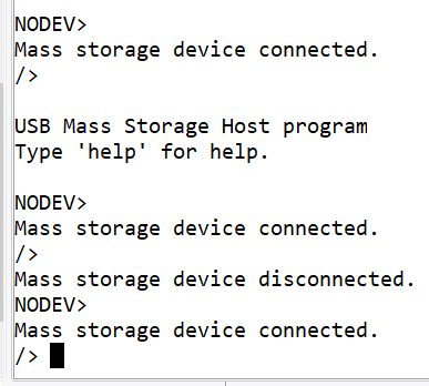
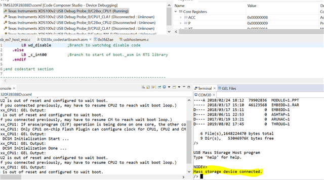
    您可以看到它未显示-"已连接大容量存储设备。" 因此、我无法再键入命令。

    然后尝试拔下 USB 闪存驱动器并将其插入设备时出现错误。

    //*****************************************************************************
    //
    // Error handling function to be called when an ASSERT is violated
    //
    //*****************************************************************************
    void __error__(const char *filename, uint32_t line)
    {
        //
        // An ASSERT condition was evaluated as false. You can use the filename and
        // line parameters to determine what went wrong.
        //
        ESTOP0;
    }


    此文件来自 usb_ex7_host_msc 示例中的.map 文件。 我相信根据您的说法、 在我暂停应用程序之后、在我再次启动之前、我应该为 PC 输入0x0000?

    codestart 
    *          0    00000000    00000002     
                      00000000    00000002     F2837xD_CodeStartBranch.obj (codestart)

    这是 运行 RAM 的 SDK 中提供的 USB_EX7_HOST_msc 示例。

    对它为什么不起作用有什么想法吗?

    感谢您的帮助。

    布伦特

  • 请注意,本文内容源自机器翻译,可能存在语法或其它翻译错误,仅供参考。如需获取准确内容,请参阅链接中的英语原文或自行翻译。

    Brent、  

    这对我来说是可行的,这些是我所做的步骤。   这与您所做的步骤完全相同、因此不能确定会出现什么问题。

    是的,入口点是正确的, PC 应该有0x000后暂停.

    1. 将 USB_EX7_HOST_msc 加载到 RAM  

    2.运行它,它检测大容量存储设备。 我还运行 ls 命令。

    3. 暂停  

    4. 将 PC 设置为 CODE_START 或入口点

    5.重新运行代码

    此致

    西达尔特

  • 请注意,本文内容源自机器翻译,可能存在语法或其它翻译错误,仅供参考。如需获取准确内容,请参阅链接中的英语原文或自行翻译。

    尊敬的  Siddharth:

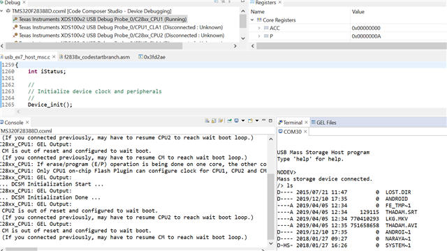
    这真的很令人困惑。  下面我详细说明了我们的不同之处。 我确实注意到、您在控制台上有打印输出、而我没有打印输出??? 修改 应用程序的方式。

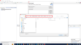
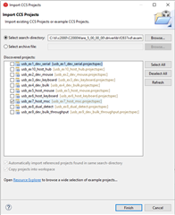
    1)在 CC I 中、从以下位置导入 MSC 项目  C:\ti\c2000\C2000Ware_5_00_00\driverlib\f2837xd\examples\cpu1\usb

    2) 2)选择 CPU1

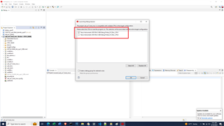
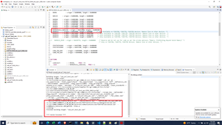
    3) 3)尝试编译应用以使其在 RAM 之外运行。 注意:从 TI SDK 导入工程后不会立即生成。 链接器命令文件未为应用程序分配足够的存储器空间。

    您也看到这个了吗?


    4) 4)修改链接器命令文件、以便创建应用程序。 如何修改链接器命令文件以使其成功构建?


    5) 5)将应用程序下载到 RAM 中

    6) 6)运行应用程序。 您可以看到它已连接/安装到 USB 设备上。 我可以执行"ls"命令。 一切都很好。

    7)我暂停申请。


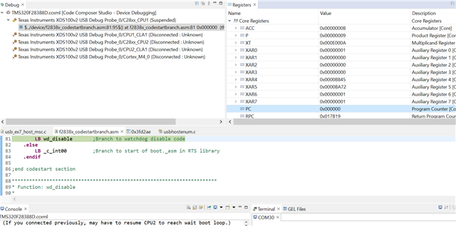
    8) 8)我将 PC 设置为0x0000。

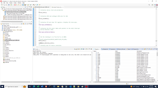
    9) 9)我选择"继续"。 如下所示、USB 从未连接/安装过。 我无法再在终端窗口中键入任何内容。 我暂停应用程序、以显示调用堆栈和当前 PC。

    我使用具有集线站的 F2837x controlCARD。

    您的台阶与我的台阶有什么不同? 我使用的是 C2000Ware 5.00且 CC 版本:12.3.0.00005。

    感谢您的帮助、

    布伦特

  • 请注意,本文内容源自机器翻译,可能存在语法或其它翻译错误,仅供参考。如需获取准确内容,请参阅链接中的英语原文或自行翻译。

    Brent、  

    我 之前使用的是 TMDSCNCD28388D 控制卡、但我也验证了 TMDSCNCD28379D 控制卡上的相同示例。   

    我已经从 C:\ti\c2000\C2000Ware_5_00_00\driverlib\f2837xd\examples\CPU1\usb 导入了相同的示例、并看到了编译错误、我已经通过更新链接器命令文件来修复了该错误  

     .数据       :>> RAMGS5 | RAMGS6TO11_combined ,  page = 1

    不管怎样,如果我暂停,将 PC 重置为0x0,然后再次运行它,它工作正常。  

    需要注意的一点是、TMS320F28379D 控制卡上有一个标记为'A:SW1'的双选择器开关、且包含两个开关。  开箱即用,开关"1"处于"ON"(打开)位置,开关"2"处于"OFF"(关闭)位置。  开关"2"需要处于"ON"位置才能将 MCU 的引脚(SCI-RX)连接到 FTDI 芯片。   但我不认为这可能是原因,因为"ls"命令在第一次对你有效。  

    此致

    西达尔特

  • 请注意,本文内容源自机器翻译,可能存在语法或其它翻译错误,仅供参考。如需获取准确内容,请参阅链接中的英语原文或自行翻译。

    尊敬的 Siddharth:

    如果您说您使用的是相同的步骤、应用程序和硬件、我能看到的唯一区别是实际的 USB 闪存驱动器。 我找到了另一个、您的测试用例现在可以正常工作。  

    我 现在可以使用具有自定义 USB 引导加载程序和客户 USB 闪存内核的 USB 闪存驱动器进行 USB 固件更新。

    我确实看到了与 SDK USB 闪存编程器使用更大的二进制文件时相同的问题、因为我的定制 USB 闪存内核基于 SDK 中的闪存内核。:  

    TMDSCNCD28379D:USB 闪存编程器不能处理更大的文件- C2000微控制器论坛- C2000 ︎ 微控制器- TI E2E 支持论坛

    布伦特