This thread has been locked.

If you have a related question, please click the "Ask a related question" button in the top right corner. The newly created question will be automatically linked to this question.

[参考译文] LAUNCHXL-F28379D:在 LaunchxL-F28379D 和 BoostXL-3phganinv 上使用 FCL_f2837x_tmdxiddk FOC 项目

Guru**** 674950 points
Other Parts Discussed in Thread: BOOSTXL-POSMGR, BOOSTXL-3PHGANINV, TMDXIDDK379D, TMDSCNCD28379D, LAUNCHXL-F28379D
请注意,本文内容源自机器翻译,可能存在语法或其它翻译错误,仅供参考。如需获取准确内容,请参阅链接中的英语原文或自行翻译。

https://e2e.ti.com/support/microcontrollers/c2000-microcontrollers-group/c2000/f/c2000-microcontrollers-forum/1289927/launchxl-f28379d-using-fcl_f2837x_tmdxiddk-foc-project-on-launchxl-f28379d-with-boostxl-3phganinv

器件型号:LAUNCHXL-F28379D
主题中讨论的其他器件:BOOSTXL-3PHGANINVTMDXIDDK379DTMDSCNCD28379D、BOOSTXL-POSMGR

您好、德州仪器

希望您对此有所帮助、我将对此进行概述、以便更好地传达消息

我们要做的事

我目前正在尝试使用 boostXL-3phganinv 并借助 SPI 绝对编码器来驱动 PMSM

我知道 TMDXIDDK379D 可能是一个更好的电路板、但我们真的想使用 GaN 逆变器而不是常规 MOSFET 来测试这一点。

此外、我们还有 HSEC 180引脚扩展坞卡和 TMDSCNCD28379D 控制卡、但我们除了一些跳线电缆外、没有用于连接 BoostXl-3phganinv 的合适 PCB、因此决定不使用。

我们的评估结果

  • 我们最初尝试使用双轴伺服驱动器项目、
    • 不过、我不太熟悉 CLA、也很难弄清楚如何禁用 eQEP、从而防止从 CLA 进行倾斜
    • 如果可能、希望收到任何关于在何处禁用 eQEP 宏的建议

我们尝试的东西

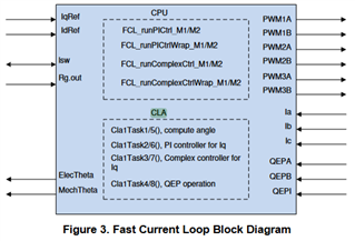
  • 因此我决定在 LaunchXL-F28379D 上使用 TMDXIDDK FCL 项目、
  • 我复制了所有 PWM 和 ADC 掩码、如下所示
    //
    // ADC and PWM Related defines for M1
    //
    #define M1_IU_ADC_BASE         ADCC_BASE           //C2, NC: Set up based board
    #define M1_IV_ADC_BASE         ADCB_BASE           //B2, NC: Set up based board
    #define M1_IW_ADC_BASE         ADCA_BASE           //A2, NC: Set up based board
    #define M1_VDC_ADC_BASE        ADCD_BASE           //D14, NC: Set up based board
    
    #define M1_IU_ADCRESULT_BASE   ADCCRESULT_BASE     //C2, NC: Set up based board
    #define M1_IV_ADCRESULT_BASE   ADCBRESULT_BASE     //B2, NC: Set up based board
    #define M1_IW_ADCRESULT_BASE   ADCARESULT_BASE     //A2, NC: Set up based board
    #define M1_VDC_ADCRESULT_BASE  ADCDRESULT_BASE     //D14, NC: Set up based board
    
    #define M1_IU_ADC_CH_NUM       ADC_CH_ADCIN2       //C2, NC: Set up based board
    #define M1_IV_ADC_CH_NUM       ADC_CH_ADCIN2       //B2, NC: Set up based board
    #define M1_IW_ADC_CH_NUM       ADC_CH_ADCIN2       //A2, NC: Set up based board
    #define M1_VDC_ADC_CH_NUM      ADC_CH_ADCIN14      //D14, NC: Set up based board
    
    #define M1_IU_ADC_SOC_NUM      ADC_SOC_NUMBER0     //C2, NC: Set up based board
    #define M1_IV_ADC_SOC_NUM      ADC_SOC_NUMBER0     //B2, NC: Set up based board
    #define M1_IW_ADC_SOC_NUM      ADC_SOC_NUMBER0     //A2, NC: Set up based board
    #define M1_VDC_ADC_SOC_NUM     ADC_SOC_NUMBER0     //D14, NC: Set up based board
    
    #define M1_IU_ADC_PPB_NUM      ADC_PPB_NUMBER1     //C2, NC: Set up based board
    #define M1_IV_ADC_PPB_NUM      ADC_PPB_NUMBER1     //B2, NC: Set up based board
    #define M1_IW_ADC_PPB_NUM      ADC_PPB_NUMBER1     //A2, NC: Set up based board
    #define M1_VDC_ADC_PPB_NUM     ADC_PPB_NUMBER1     //D14, NC: Set up based board
    
    #define M1_U_CMPSS_BASE        CMPSS6_BASE         // NC: Set up based board
    #define M1_V_CMPSS_BASE        CMPSS3_BASE         // NC: Set up based board
    #define M1_W_CMPSS_BASE        CMPSS1_BASE         // NC: Set up based board
    
    #define M1_ADC_TRIGGER_SOC     ADC_TRIGGER_EPWM1_SOCA  // NC: Set up based board
    
    #define M1_U_PWM_BASE          EPWM1_BASE          // NC: Set up based board
    #define M1_V_PWM_BASE          EPWM2_BASE          // NC: Set up based board
    #define M1_W_PWM_BASE          EPWM3_BASE          // NC: Set up based board
    
    //
    // Analog scaling with ADC
    //
    #define M1_ADC_PU_SCALE_FACTOR          0.000244140625     // 1/2^12
    #define M1_ADC_PU_PPB_SCALE_FACTOR      0.000488281250     // 1/2^11
    
    // Current Scale
    //
    #define M1_MAXIMUM_SCALE_CURRENT        27.0
    #define M1_CURRENT_SF                   (M1_MAXIMUM_SCALE_CURRENT / 4096.0)
    #define M1_CURRENT_INV_SF               (4096.0 / M1_MAXIMUM_SCALE_CURRENT)
    
    //
    // Voltage Scale
    //
    #define M1_MAXIMUM_SCALE_VOLATGE        74.1
    #define M1_VOLTAGE_SF                   (M1_MAXIMUM_SCALE_VOLATGE / 4096.0)
    #define M1_VOLTAGE_INV_SF               (4096.0 / M1_MAXIMUM_SCALE_VOLATGE)
  • 已根据我的需要配置所有 GPIO
    void configureGPIO(void)
    {
        uint16_t pin;
    
        //
        // main inverter PWM GPIO init
        // PWM1 - U
        // PWM2 - V
        // PWM3 - W
        //
        // GPIO0->EPWM1A->UH_M1
        GPIO_setMasterCore(0, GPIO_CORE_CPU1);
        GPIO_setPinConfig(GPIO_0_EPWM1A);
        GPIO_setPadConfig(0, GPIO_PIN_TYPE_STD);
    
        // GPIO1->EPWM1B->UL_M1
        GPIO_setMasterCore(1, GPIO_CORE_CPU1);
        GPIO_setPinConfig(GPIO_1_EPWM1B);
        GPIO_setPadConfig(1, GPIO_PIN_TYPE_STD);
    
        // GPIO2->EPWM2A->VH_M1
        GPIO_setMasterCore(2, GPIO_CORE_CPU1);
        GPIO_setPinConfig(GPIO_2_EPWM2A);
        GPIO_setPadConfig(2, GPIO_PIN_TYPE_STD);
    
        // GPIO3->EPWM2B->VL_M1
        GPIO_setMasterCore(3, GPIO_CORE_CPU1);
        GPIO_setPinConfig(GPIO_3_EPWM2B);
        GPIO_setPadConfig(3, GPIO_PIN_TYPE_STD);
    
        // GPIO4->EPWM3A->WH_M1
        GPIO_setMasterCore(4, GPIO_CORE_CPU1);
        GPIO_setPinConfig(GPIO_4_EPWM3A);
        GPIO_setPadConfig(4, GPIO_PIN_TYPE_STD);
    
        // GPIO5->EPWM3B->WL_M1
        GPIO_setMasterCore(5, GPIO_CORE_CPU1);
        GPIO_setPinConfig(GPIO_5_EPWM3B);
        GPIO_setPadConfig(5, GPIO_PIN_TYPE_STD);
    
    
        //
        // Configure GPIO8 as ePWM5A for SD1, Ch1/2 clock
        // Configure GPIO9 as ePWM5B for SD1, Ch3 clock
        //
        GPIO_setPadConfig(8, GPIO_PIN_TYPE_STD);
        GPIO_setPinConfig(GPIO_8_EPWM5A);
    
        GPIO_setPadConfig(9, GPIO_PIN_TYPE_STD);
        GPIO_setPinConfig(GPIO_9_EPWM5B);
    
        //
        // GPIO18 is used as PushPull output to indicate the end of computation when
        // compared against the SOC signal
        GPIO_setMasterCore(18, GPIO_CORE_CPU1);
        GPIO_setPinConfig(GPIO_18_GPIO18);
        GPIO_setPadConfig(18, GPIO_PIN_TYPE_STD);
        GPIO_setDirectionMode(18, GPIO_DIR_MODE_OUT);
    
        //
        // Setup GPIO for QEP operation
        //
        // QEP1A
        GPIO_setMasterCore(20, GPIO_CORE_CPU1);
        GPIO_setPadConfig(20, GPIO_PIN_TYPE_STD);
        GPIO_setDirectionMode(20, GPIO_DIR_MODE_IN);
        GPIO_setQualificationMode(20, GPIO_QUAL_3SAMPLE);
        GPIO_setPinConfig(GPIO_20_EQEP1A);
    
        // QEP1B
        GPIO_setMasterCore(21, GPIO_CORE_CPU1);
        GPIO_setPadConfig(21, GPIO_PIN_TYPE_STD);
        GPIO_setDirectionMode(21, GPIO_DIR_MODE_IN);
        GPIO_setQualificationMode(21, GPIO_QUAL_3SAMPLE);
        GPIO_setPinConfig(GPIO_21_EQEP1B);
    
        // QEP1I
        GPIO_setMasterCore(23, GPIO_CORE_CPU1);
        GPIO_setPadConfig(23, GPIO_PIN_TYPE_STD);
        GPIO_setDirectionMode(23, GPIO_DIR_MODE_IN);
        GPIO_setQualificationMode(23, GPIO_QUAL_3SAMPLE);
        GPIO_setPinConfig(GPIO_23_EQEP1I);
    
        // GPIO28->SCIRXDA
        GPIO_setMasterCore(28, GPIO_CORE_CPU1);
        GPIO_setPadConfig(28, GPIO_PIN_TYPE_STD);
        GPIO_setPinConfig(GPIO_28_SCIRXDA);
    
        // GPIO29->SCITXDA
        GPIO_setMasterCore(29, GPIO_CORE_CPU1);
        GPIO_setPadConfig(29, GPIO_PIN_TYPE_STD);
        GPIO_setPinConfig(GPIO_29_SCITXDA);
    
        // Configure GPIO used for Trip Mechanism
    
        // GPIO input for reading the status of the LEM-overcurrent macro block
        // (active low), GPIO40 could trip PWM based on this, if desired
        // Configure as Input
        GPIO_setPinConfig(GPIO_40_GPIO40);           // choose GPIO for mux option
        GPIO_setDirectionMode(40, GPIO_DIR_MODE_IN); // set as input
        GPIO_setPadConfig(40, GPIO_PIN_TYPE_INVERT); // invert the input
    
        //Select GPIO40 as INPUTXBAR2
        XBAR_setInputPin(XBAR_INPUT2, 40);
    
        // Clearing the Fault(active low), GPIO41
        // Configure as Output
        GPIO_setPinConfig(GPIO_41_GPIO41);            // choose GPIO for mux option
        GPIO_setDirectionMode(41, GPIO_DIR_MODE_OUT); // set as output
        GPIO_writePin(41, 1);
    
        // Forcing IPM Shutdown (Trip) using GPIO58 (Active high)
        // Configure as Output
        GPIO_setPinConfig(GPIO_58_GPIO58);            // choose GPIO for mux option
        GPIO_setDirectionMode(58, GPIO_DIR_MODE_OUT); // set as output
        GPIO_writePin(58, 0);
    
        // GPIO31->LED
        GPIO_setMasterCore(31, GPIO_CORE_CPU1);
        GPIO_setPadConfig(31, GPIO_PIN_TYPE_STD);
        GPIO_setPinConfig(GPIO_31_GPIO31);
        GPIO_setDirectionMode(31, GPIO_DIR_MODE_OUT);
    
        //
        // BoostXL enable GPIO17
        // compared against the SOC signal
        GPIO_setMasterCore(124, GPIO_CORE_CPU1);
        GPIO_setPinConfig(GPIO_124_GPIO124);
        GPIO_writePin(124, 1);
        GPIO_setDirectionMode(98, GPIO_DIR_MODE_OUT);
        GPIO_setPadConfig(98, GPIO_PIN_TYPE_PULLUP);
        //
        // SDFM GPIO configurations
        //
        for(pin = 48; pin <= 53; pin++)
        {
            GPIO_setMasterCore(pin, GPIO_CORE_CPU1);
            GPIO_setDirectionMode(pin, GPIO_DIR_MODE_IN);
            GPIO_setPadConfig(pin, GPIO_PIN_TYPE_STD);
            GPIO_setQualificationMode(pin, GPIO_QUAL_ASYNC);
        }
    
        // GPIO58->SPISIMOA_M1
        GPIO_setMasterCore(58, GPIO_CORE_CPU1);
        GPIO_setPinConfig(GPIO_58_SPISIMOA);
        GPIO_setDirectionMode(58, GPIO_DIR_MODE_OUT);
        GPIO_setPadConfig(58, GPIO_PIN_TYPE_STD);
    
        // GPIO59->SPISOMIA_M1
        GPIO_setMasterCore(59, GPIO_CORE_CPU1);
        GPIO_setPinConfig(GPIO_59_SPISOMIA);
        GPIO_setDirectionMode(59, GPIO_DIR_MODE_IN);
        GPIO_setPadConfig(59, GPIO_PIN_TYPE_STD);
    
        // GPIO60->SPICLKA_M1
        GPIO_setMasterCore(60, GPIO_CORE_CPU1);
        GPIO_setPinConfig(GPIO_60_SPICLKA);
        GPIO_setDirectionMode(60, GPIO_DIR_MODE_OUT);
        GPIO_setPadConfig(60, GPIO_PIN_TYPE_STD);
    
        // GPIO61->SPISTEA_M1
        GPIO_setMasterCore(61, GPIO_CORE_CPU1);
        GPIO_setPinConfig(GPIO_61_SPISTEA);
        GPIO_setDirectionMode(61, GPIO_DIR_MODE_OUT);
        GPIO_setPadConfig(61, GPIO_PIN_TYPE_STD);
    
        // SD1 Ch1 - Ishunt - V
        GPIO_setPinConfig(GPIO_48_SD1_D1);
        GPIO_setPinConfig(GPIO_49_SD1_C1);
    
        // SD1 Ch2 - Ishunt - W
        GPIO_setPinConfig(GPIO_50_SD1_D2);
        GPIO_setPinConfig(GPIO_51_SD1_C2);
    
        // SD1 Ch3 - DC Bus
        GPIO_setPinConfig(GPIO_52_SD1_D3);
        GPIO_setPinConfig(GPIO_53_SD1_C3);
    
        return;
    }
  • 并在 LaunchXL-F28379D 上刷写了该代码

发生了什么事

  • ADCIN14正常工作并测量 VDC
  • SPI 端口正常工作并正确获取 SPI 数据
  • 用于 UVW 相的 ADC 正常工作(我认为)
  • 构建级1 PWM 输出 DOES NOT 工作
  • 尝试连接正交编码器并将编码器类型设置为 QEP 编码器。 即使在 buildLevel 1中、EPWM1也不会执行
  • 不过、当将 GPIO 从 HSEC 卡连接到 BoostXL-3phganinv 时、PWM 信号是实时的。
    • 我发现这很奇怪、这两个芯片不是同在吗? 此外、双轴伺服驱动器和 tmdxiddk 都具有为 PWM 定义的相同 GPIO

我们非常感谢您提供任何帮助、如果您希望了解更多代码、敬请告知。 我们在 motorcontrolISR 中调用了 SPI 函数、这是对代码进行的唯一修改

谢谢!

汉索尔

  • 请注意,本文内容源自机器翻译,可能存在语法或其它翻译错误,仅供参考。如需获取准确内容,请参阅链接中的英语原文或自行翻译。

    //#############################################################################
    //
    // FILE:    fcl_f2837x_tmdxiddk.c
    //
    // TITLE:   servo motor drive on the related kits
    //
    // Group:   C2000
    //
    // Target Family: F2837x
    //
    //#############################################################################
    // $Copyright:
    // Copyright (C) 2017-2023 Texas Instruments Incorporated - http://www.ti.com/
    // Redistribution and use in source and binary forms, with or without
    // modification, are permitted provided that the following conditions
    // are met:
    //
    //   Redistributions of source code must retain the above copyright
    //   notice, this list of conditions and the following disclaimer.
    //
    //   Redistributions in binary form must reproduce the above copyright
    //   notice, this list of conditions and the following disclaimer in the
    //   documentation and/or other materials provided with the
    //   distribution.
    //
    //   Neither the name of Texas Instruments Incorporated nor the names of
    //   its contributors may be used to endorse or promote products derived
    //   from this software without specific prior written permission.
    //
    // THIS SOFTWARE IS PROVIDED BY THE COPYRIGHT HOLDERS AND CONTRIBUTORS
    // "AS IS" AND ANY EXPRESS OR IMPLIED WARRANTIES, INCLUDING, BUT NOT
    // LIMITED TO, THE IMPLIED WARRANTIES OF MERCHANTABILITY AND FITNESS FOR
    // A PARTICULAR PURPOSE ARE DISCLAIMED. IN NO EVENT SHALL THE COPYRIGHT
    // OWNER OR CONTRIBUTORS BE LIABLE FOR ANY DIRECT, INDIRECT, INCIDENTAL,
    // SPECIAL, EXEMPLARY, OR CONSEQUENTIAL DAMAGES (INCLUDING, BUT NOT
    // LIMITED TO, PROCUREMENT OF SUBSTITUTE GOODS OR SERVICES; LOSS OF USE,
    // DATA, OR PROFITS; OR BUSINESS INTERRUPTION) HOWEVER CAUSED AND ON ANY
    // THEORY OF LIABILITY, WHETHER IN CONTRACT, STRICT LIABILITY, OR TORT
    // (INCLUDING NEGLIGENCE OR OTHERWISE) ARISING IN ANY WAY OUT OF THE USE
    // OF THIS SOFTWARE, EVEN IF ADVISED OF THE POSSIBILITY OF SUCH DAMAGE.
    // $
    //#############################################################################
    //
    // Peripheral functions:
    // EPWMs
    //  - EPWM1, EPWM2, EPWM3 ---> Inverter PWMs for phases A, B, C
    //  - EPWM5  ---> clk for Sigma Delta
    //  - EPWM6  ---> Resolver feedback sampling @ 160KHz
    //  - EPWM11 ---> sync SD filter windows with motor control PWMs
    //  - EPWM4  ---> Not available for users if EnDAT / BiSS interface is active
    //
    // SPIs
    //  - SPIB  ---> Not available for users if EnDAT / BiSS interface is active
    //
    // Analog to Digital Conversion channels
    //  ADC A4/C+  --->  Ifb-SV
    //  ADC B4/C+  ---> Ifb-SW
    //  ADC A2/C+  ---> LEM V
    //  ADC B2/C+  ---> LEM W
    //  ADC D1     ---> R_SIN
    //  ADC C1     ---> R_COS
    //  ADC C3     ---> Vfb-U
    //  ADC A3     ---> Vfb-V
    //  ADC B3     ---> Vfb-W
    //  ADC B0     ---> Vfb-Bus
    //
    // Analog Signals brought in but not sampled
    //  ADC C2/C+  ---> Ifb-SU
    //  ADC A5     --->
    //  ADC C0/C+  ---> SC-A2
    //  ADC D0/C+  ---> SC-B2
    //  ADC D2/C+  ---> SC-R
    //
    // DAC-A  ---> Resolver carrier excitation
    // DAC-B  ---> General purpose display
    // DAC-C  ---> General purpose display
    //
    // Include header files used in the main function
    // define float maths and then include IQmath library
    //
    
    #include <stdint.h>
    #include "fcl_cpu_cla.h"
    #include "fcl_f2837x_tmdxiddk_settings.h"
    #include "fcl_f2837x_sfra_settings.h"
    #include "fcl_f2837x_enum.h"
    #include "fcl_tformat_f2837x_config.h"
    
    //
    // Instrumentation code for timing verifications
    //
    #define SETGPIO18_HIGH  GPIO_writePin(18, 1);
    #define SETGPIO18_LOW   GPIO_writePin(18, 0);
    //
    //Encoder SPI Mask
    //
    #define MU150_OP_SDAD 0xA6
    #define SPI_PACKET_SIZE (4U)
    
    //
    // display variable A (in pu) on DAC
    //
    #define  DAC_MACRO_PU(A)  ((1.0 + A) * 2048)
    #define  PU_MACRO(A)  ((A > 1000) ? 1000 : (A < -1000) ? -1000 : A)
    
    // **********************************************************
    // ********************* Functions **************************
    // **********************************************************
    #ifdef _FLASH
    #ifndef __cplusplus
    #pragma CODE_SECTION(motorControlISR,".TI.ramfunc");
    #endif
    #endif
    
    // **********************************************************
    // ******************* Extern Functions *********************
    // **********************************************************
    
    // **********************************************************
    // ******** Prototype statements for Local Functions ********
    // **********************************************************
    #pragma INTERRUPT (motorControlISR, LPI)
    __interrupt void motorControlISR(void);
    
    // ****************************************************************************
    // Device / peripheral config functions
    // ****************************************************************************
    void configureADC(void);
    void initSPIAMaster();
    void SPIEncoderRead(int32_t *encoder_readout, int32_t *encoder_revolution);
    void readSPIPosition(int32_t position, int16_t isr_cntr);
    void configureCLA(void);
    void configureCMPSS(uint32_t base, int16_t Hi, int16_t Lo);
    void configureCMPSSFilter(uint32_t base, uint16_t curHi, uint16_t curLo);
    void configureDAC(void);
    void configureGPIO(void);
    void configureHVDMCProtection(void);
    void configurePIControllers(void);
    void configurePositionSensing(void);
    void configurePWM(void);
    void configurePWM_1chUpCnt(uint32_t base, uint16_t period);
    void configurePWM_1chUpDwnCnt(uint32_t base, uint16_t period, int16_t db);
    void configureSDFM(void);
    
    //*****************************************************************************
    // Motor drive utility functions
    //*****************************************************************************
    float32_t refPosGen(float32_t out);
    float32_t refPosGen8(float32_t in, float32_t out);
    float32_t ramper(float32_t in, float32_t out, float32_t rampDelta);
    
    #if(BUILDLEVEL > FCL_LEVEL2)
    static inline void getFCLTime(void);
    #endif
    
    //*****************************************************************************
    // SFRA utility functions
    //*****************************************************************************
    #if(BUILDLEVEL == FCL_LEVEL6)
    static inline void injectSFRA(void);
    static inline void collectSFRA(void);
    #endif
    
    //
    // SDFM current sense
    //
    #if((BUILDLEVEL == FCL_LEVEL2) || (CURRENT_SENSE == SD_CURRENT_SENSE))
    static inline void getSDFMCurrent(void);
    #endif  //((BUILDLEVEL == FCL_LEVEL2) || (CURRENT_SENSE == SD_CURRENT_SENSE))
    
    //
    // T-format functions
    //
    #if (POSITION_ENCODER == T_FORMAT_ENCODER)
    static inline void startTformatEncOperation(void);
    #endif  // (POSITION_ENCODER == T_FORMAT_ENCODER)
    
    static inline float32_t angleEstimator_Tformat(void);
    
    //
    // State Machine function prototypes
    //------------------------------------
    // Alpha states
    //
    void A0(void);  //state A0
    void B0(void);  //state B0
    void C0(void);  //state C0
    
    // A branch states
    void A1(void);  //state A1
    void A2(void);  //state A2
    void A3(void);  //state A3
    
    // B branch states
    void B1(void);  //state B1
    void B2(void);  //state B2
    void B3(void);  //state B3
    
    // C branch states
    void C1(void);  //state C1
    void C2(void);  //state C2
    void C3(void);  //state C3
    
    // Variable declarations
    void (*Alpha_State_Ptr)(void);  // Base States pointer
    void (*A_Task_Ptr)(void);       // State pointer A branch
    void (*B_Task_Ptr)(void);       // State pointer B branch
    void (*C_Task_Ptr)(void);       // State pointer C branch
    
    //*****************************************************************************
    // Cla1Task function externs (tasks 1-4 are owned by the FCL library)
    //*****************************************************************************
    extern __interrupt void Cla1Task5(void);
    extern __interrupt void Cla1Task6(void);
    extern __interrupt void Cla1Task7(void);
    extern __interrupt void Cla1Task8(void);
    
    //
    // These are defined by the linker file
    //
    extern uint32_t Cla1funcsLoadStart;
    extern uint32_t Cla1funcsLoadSize;
    extern uint32_t Cla1funcsRunStart;
    
    extern uint32_t Cla1ConstRunStart;
    extern uint32_t Cla1ConstLoadStart;
    extern uint32_t Cla1ConstLoadSize;
    
    
    // ****************************************************************************
    // Variables for CPU control
    // ****************************************************************************
    uint32_t adcHandle[4] = {ADCA_BASE,
                             ADCB_BASE,
                             ADCC_BASE,
                             ADCD_BASE
    };
    
    // EPWM1 - Phase U
    // EPWM2 - Phase V
    // EPWM3 - Phase W
    uint32_t pwmHandle[3] = {EPWM1_BASE,
                             EPWM2_BASE,
                             EPWM3_BASE
    };
    
    uint32_t dacHandle[3] = {DACA_BASE,
                             DACB_BASE,
                             DACC_BASE
    };
    
    uint16_t vTimer0[4] = {0};  // Virtual Timers slaved off CPU Timer 0 (A events)
    uint16_t vTimer1[4] = {0};  // Virtual Timers slaved off CPU Timer 1 (B events)
    uint16_t vTimer2[4] = {0};  // Virtual Timers slaved off CPU Timer 2 (C events)
    uint16_t serialCommsTimer = 0;
    
    //*********************** USER Variables **************************************
    // Global variables used in this system
    //*****************************************************************************
    
    #if(CNGD == HOT)
    float32_t offset_shntV = 0;    // offset in shunt current V fbk channel @ 0A
    float32_t offset_shntW = 0;    // offset in shunt current W fbk channel @ 0A
    float32_t offset_shntU = 0;    // offset in shunt current U fbk channel @ 0A
    #endif
    
    // ****************************************************************************
    // Variables for current measurement
    // ****************************************************************************
    // Offset calibration routine is run to calibrate for any offsets on the opamps
    
    float32_t offset_lemV = 0;     // offset in LEM current V fbk channel @ 0A
    float32_t offset_lemW = 0;     // offset in LEM current W fbk channel @ 0A
    
    volatile float32_t offset_SDFMV;  // offset in SD current V fbk channel @ 0A
    volatile float32_t offset_SDFMW;  // offset in SD current W fbk channel @ 0A
    
    float32_t K1 = 0.9980001;        // Offset filter coefficient K1: 0.05/(T+0.05);
    float32_t K2 = 0.0019999;        // Offset filter coefficient K2: T/(T+0.05);
    
    uint16_t offsetCalCounter = 0;
    
    //SD Trip Level - scope for additional work
    uint16_t hlt = 0x7FFF;
    uint16_t llt = 0x0;
    
    float32_t curLimit = 8.0;
    
    // CMPSS parameters for Over Current Protection
    uint16_t clkPrescale = 20;
    uint16_t sampWin     = 30;
    uint16_t thresh      = 18;
    uint16_t LEM_curHi   = LEM(8.0);
    uint16_t LEM_curLo   = LEM(8.0);
    uint16_t SHUNT_curHi = SHUNT(8.0);
    uint16_t SHUNT_curLo = SHUNT(8.0);
    
    // ****************************************************************************
    // Flag variables
    // ****************************************************************************
    volatile uint16_t enableFlag = false;
    
    uint32_t isrTicker = 0;
    
    uint16_t backTicker = 0;
    uint16_t tripFlagDMC = 0;        //PWM trip status
    uint16_t clearTripFlagDMC = 0;
    MotorRunStop_e runMotor = MOTOR_STOP;
    
    uint16_t ledCnt1 = 0;
    
    uint16_t speedLoopPrescaler = 10;      // Speed loop pre scalar
    uint16_t speedLoopCount = 1;           // Speed loop counter
    
    volatile uint16_t lsw2EntryFlag = 0;
    
    // ****************************************************************************
    // Variables for Fast Current Loop
    // ****************************************************************************
    volatile  uint16_t FCL_cycleCount = 0;
    uint16_t  fclClrCntr = 0;
    uint16_t  fclCycleCountMax = 0;
    float32_t fclLatencyInMicroSec = 0;    // PWM update latency since sampling
    float32_t maxModIndex = 0;             // max modulation index
    
    // ****************************************************************************
    // Variables for Field Oriented Control
    // ****************************************************************************
    float32_t T = 0.001f / ISR_FREQUENCY;  // Samping period (sec), see parameter.h
    float32_t VdTesting = 0.0f;          // Vd reference (pu)
    float32_t VqTesting = 0.10f;         // Vq reference (pu)
    float32_t IdRef     = 0.0f;          // Id reference (pu)
    float32_t tempIdRef = 0.0f;          // tempId reference (pu)
    float32_t IqRef     = 0.0f;          // Iq reference (pu)
    float32_t speedRef  = 0.0f;          // For Closed Loop tests
    float32_t lsw1Speed = 0.02f;         // initial force rotation speed in search
                                        // of QEP index pulse
    
    // Instance a few transform objects
    IPARK  ipark1  = IPARK_DEFAULTS;
    
    // Instance PI(D) regulators to regulate the d and q  axis currents,
    // speed and position
    PIDREG3         pid_pos = PIDREG3_DEFAULTS;          // (optional - for eval)
    PI_CONTROLLER   pi_pos  = PI_CONTROLLER_DEFAULTS;
    PID_CONTROLLER  pid_spd = {PID_TERM_DEFAULTS,
                               PID_PARAM_DEFAULTS,
                               PID_DATA_DEFAULTS};
    
    // Instance a ramp controller to smoothly ramp the frequency
    RMPCNTL rc1 = RMPCNTL_DEFAULTS;
    
    // Instance a phase voltage calculation
    PHASEVOLTAGE volt1 = PHASEVOLTAGE_DEFAULTS;
    
    // Instance a speed measurement calc
    SPEED_MEAS_QEP  speed1;
    
    // Variables for Position Sensor Suite
    float32_t posEncElecTheta[ENCODER_MAX_TYPES] = {0};
    float32_t posEncMechTheta[ENCODER_MAX_TYPES] = {0};
    
    float32_t alignCntr = 0;
    float32_t alignCnt = 20000;
    float32_t alignInitCnt = 15000;
    float32_t IdRef_start = M_ID_START;
    float32_t IdRef_run = 0;
    
    // Variables for position reference generation and control
    // =========================================================
    float32_t posArray[8] = {1.5, -1.5, 2.5, -2.5};
    float32_t posCntr = 0;
    float32_t posCntrMax = 5000;
    float32_t posSlewRate = 0.001;
    
    int16_t posPtrMax = 2;
    int16_t posPtr = 0;
    
    // ****************************************************************************
    // Variables for Datalog module
    // ****************************************************************************
    float32_t DBUFF_4CH1[200] = {0};
    float32_t DBUFF_4CH2[200] = {0};
    float32_t DBUFF_4CH3[200] = {0};
    float32_t DBUFF_4CH4[200] = {0};
    float32_t dlogCh1 = 0;
    float32_t dlogCh2 = 0;
    float32_t dlogCh3 = 0;
    float32_t dlogCh4 = 0;
    
    // Create an instance of DATALOG Module
    DLOG_4CH_F dlog_4ch1;
    
    // ****************************************************************************
    // Variables for SFRA module
    // ****************************************************************************
    #if(BUILDLEVEL == FCL_LEVEL6)
    extern SFRA_F32 sfra1;
    SFRATest_e      sfraTestLoop = SFRA_TEST_D_AXIS;  //speedLoop;
    uint32_t        sfraCollectStart = 0;
    float32_t       sfraNoiseD = 0;
    float32_t       sfraNoiseQ = 0;
    float32_t       sfraNoiseW = 0;
    #endif
    
    /*-----------------------------------------------------------------------------
    Define the structure of the Encoder Driver Object
    -----------------------------------------------------------------------------*/
    typedef struct {
            float32_t ElecTheta;       // Output: Motor Electrical angle
            float32_t MechTheta;       // Output: Motor Mechanical Angle
            float32_t RawTheta;        // Variable: Raw position data from encoder
            float32_t Speed;           // Variable: Speed data from encoder
            float32_t InitTheta;       // Parameter: Raw angular offset between
                                       //            encoder index and phase A
            float32_t MechScaler;      // Parameter: 0.9999/total count
            float32_t StepsPerTurn;    // Parameter: Number of discrete positions
            uint16_t  PolePairs;       // Parameter: Number of pole pairs
    
        }  ABS_ENCODER;
    
    
    /*-----------------------------------------------------------------------------
    Default initializer for the Encoder Object.
    -----------------------------------------------------------------------------*/
    #define ABSENC_DEFAULTS {                                                      \
                       0x0,            /*  ElecTheta       */                      \
                       0x0,            /*  MechTheta       */                      \
                       0x0,            /*  RawTheta        */                      \
                       0x0,            /*  Speed           */                      \
                       0x0,            /*  InitTheta       */                      \
                       0x00020000,     /*  MechScaler      */                      \
                       0x0,            /*  StepsPerTurn    */                      \
                       4               /*  PolePairs       */                      \
       }
    
    ABS_ENCODER     tFormat = ABSENC_DEFAULTS;
    
    SPD_OBSERVER   spdObs = SPD_OBSERVER_DEFAULTS;     // speed observer
    float32_t      angMax = BASE_FREQ * 0.001 / ISR_FREQUENCY;
    float32_t      tformatAngle;
    float32_t      tformatSpd;
    
    uint16_t tFormat_encCmdStatus = ENC_CLOSE;
    uint16_t tFormat_crcError = 0;
    uint16_t tFormat_dataId;
    
    uint32_t retVal1, crcResult, position, turns; // tformat
    
    // ****************************************************************************
    // Functions
    // ****************************************************************************
    
    //Function that initializes the variables for Fast current Loop library
    void initFCLVars()
    {
    
    #if(SAMPLING_METHOD == SINGLE_SAMPLING)
        maxModIndex = (TPWM_CARRIER - (2 * FCL_COMPUTATION_TIME)) / TPWM_CARRIER;
        FCL_params.carrierMid = maxModIndex * INV_PWM_HALF_TBPRD * 0x10000L;
    #elif(SAMPLING_METHOD == DOUBLE_SAMPLING)
        maxModIndex = (TPWM_CARRIER - (4 * FCL_COMPUTATION_TIME)) / TPWM_CARRIER;
        FCL_params.carrierMid = INV_PWM_HALF_TBPRD * 0x10000L;
    #endif
        FCL_params.adcScale   = -M1_ADC_PU_PPB_SCALE_FACTOR;//ADC_PU_PPB_SCALE_FACTOR * LEM_TO_SHUNT;
        FCL_params.sdfmScale  = SD_PU_SCALE_FACTOR * SDFM_TO_SHUNT;
        FCL_params.cmidsqrt3   = FCL_params.carrierMid * sqrtf(3.0f);
    
        FCL_params.tSamp = (1.0F / SAMPLING_FREQ);
        FCL_params.Rd    = RS;
        FCL_params.Rq    = RS;
        FCL_params.Ld    = LS;
        FCL_params.Lq    = LS;
        FCL_params.BemfK = 0.8;
        FCL_params.Ibase = BASE_SHUNT_CURRENT; // LEM sensing is scaled to match
                                               // with shunt sensing
        FCL_params.Wbase = 2.0 * PI * BASE_FREQ;
        FCL_params.wccD  = CUR_LOOP_BANDWIDTH,
        FCL_params.wccQ  = CUR_LOOP_BANDWIDTH;
    
        return;
    }
    
    //
    // Read and update DC BUS voltage for FCL to use
    //
    static inline float32_t getVdc(void)
    {
        float32_t vdc;
    
        /*vdc = ((int32_t)SDFM_getFilterData(SDFM1_BASE, VDC_SDFM_FILTER) >> 16) *
                          SD_VOLTAGE_SENSE_SCALE;*/
    
        vdc = HWREGH(M1_VDC_ADCRESULT_BASE + ADC_PPBxRESULT_OFFSET_BASE + M1_VDC_ADC_PPB_NUM * 2) * (M1_MAXIMUM_SCALE_VOLATGE / 4096.0);
        if(vdc < 1.0)
        {
            vdc = 1.0;
        }
    
        return(vdc);
    }
    
    //
    // Read motor phase current from shunt resistor using SDFM
    //
    #if((BUILDLEVEL == FCL_LEVEL2) || (CURRENT_SENSE == SD_CURRENT_SENSE))
    static inline void getSDFMCurrent(void)
    {
        currentSenV =
           (float32_t)(((int32_t)SDFM_getFilterData(SDFM1_BASE, IV_SDFM_FILTER)>>16)
                * FCL_params.sdfmScale) - offset_SDFMV;
    
        currentSenW =
           (float32_t)(((int32_t)SDFM_getFilterData(SDFM1_BASE, IW_SDFM_FILTER)>>16)
                * FCL_params.sdfmScale) - offset_SDFMW;
        return;
    }
    #endif  //((BUILDLEVEL == FCL_LEVEL2) || (CURRENT_SENSE == SD_CURRENT_SENSE))
    
    // ****************************************************************************
    // Get FCL timing details - time stamp taken in library after PWM update
    // ****************************************************************************
    #if(BUILDLEVEL > FCL_LEVEL2)
    static inline void getFCLTime(void)
    {
        SETGPIO18_HIGH;
    
        if(EPWM_getTimeBaseCounterValue(EPWM1_BASE) < FCL_cycleCount)
        {
            FCL_cycleCount = EPWM_getTimeBasePeriod(EPWM1_BASE) - FCL_cycleCount;
        }
        if(fclCycleCountMax < FCL_cycleCount)
        {
            fclCycleCountMax = FCL_cycleCount;
        }
        if(fclClrCntr)
        {
            fclCycleCountMax = 0;
            fclClrCntr = 0;
        }
    
        fclLatencyInMicroSec = (fclCycleCountMax) * 0.01; //for 100MHz PWM clock
    
        SETGPIO18_LOW;
    
        return;
    }
    #endif  // (BUILDLEVEL > FCL_LEVEL2)
    
    //
    // Build level 6 : SFRA support functions
    //
    #if(BUILDLEVEL == FCL_LEVEL6)
    // *************************************************************************
    // Using SFRA tool :
    // =================
    //      - INJECT noise
    //      - RUN the controller
    //      - CAPTURE or COLLECT the controller output
    // From a controller analysis standpoint, this sequence will reveal the
    // output of controller for a given input, and therefore, good for analysis
    // *************************************************************************
    static inline void injectSFRA(void)
    {
        if(sfraTestLoop == SFRA_TEST_D_AXIS)
        {
            sfraNoiseD = SFRA_F32_inject(0.0);
        }
        else if(sfraTestLoop == SFRA_TEST_Q_AXIS)
        {
            sfraNoiseQ = SFRA_F32_inject(0.0);
        }
        else if(sfraTestLoop == SFRA_TEST_SPEEDLOOP)
        {
            sfraNoiseW = SFRA_F32_inject(0.0);
        }
    
        return;
    }
    
    // ****************************************************************************
    static inline void collectSFRA(void)
    {
        if(sfraTestLoop == SFRA_TEST_D_AXIS)
        {
            SFRA_F32_collect(&pi_id.out, &pi_id.fbk);
        }
        else if(sfraTestLoop == SFRA_TEST_Q_AXIS)
        {
            SFRA_F32_collect(&pi_iq.out, &pi_iq.fbk);
        }
        else if(sfraTestLoop == SFRA_TEST_SPEEDLOOP)
        {
            SFRA_F32_collect(&pid_spd.term.Out, &pid_spd.term.Fbk);
        }
    
        return;
    }
    #endif
    
    // ****************************************************************************
    // setup CPU Timer
    // ****************************************************************************
    void setupCpuTimer(uint32_t base, uint32_t periodCount)
    {
        CPUTimer_setPreScaler(CPUTIMER0_BASE, 0);  // divide by 1 (SYSCLKOUT)
        CPUTimer_setPeriod(base, periodCount);
        CPUTimer_stopTimer(base);                  // Stop timer / reload / restart
        CPUTimer_setEmulationMode(base,
                                  CPUTIMER_EMULATIONMODE_STOPAFTERNEXTDECREMENT);
        CPUTimer_reloadTimerCounter(base);  // Reload counter with period value
        CPUTimer_resumeTimer(base);
    
        return;
    }
    
    //
    //*****************************************************************************
    // main() function enter
    //*****************************************************************************
    void main(void)
    {
        //
        // Initialize device clock and peripherals
        //
        Device_init();
    
        //
        // Disable pin locks and enable internal pullups.
        //
        Device_initGPIO();
    
        // Waiting for enable flag set
        while(enableFlag == false)
        {
            backTicker++;
        }
    
        //findout the FCL SW version information
        while(FCL_getSwVersion() != 0x00000007)
        {
            backTicker++;
        }
    
        // Clear all interrupts and initialize PIE vector table:
        // Initialize the PIE control registers to their default state.
        // The default state is all PIE interrupts disabled and flags
        // are cleared.
        Interrupt_initModule();
    
        // Initialize the PIE vector table with pointers to the shell Interrupt
        // Service Routines (ISR).
        // This will populate the entire table, even if the interrupt
        // is not used in this example.  This is useful for debug purposes.
        Interrupt_initVectorTable();
    
        // *************** SFRA & SFRA_GUI COMM INIT CODE START *******************
    #if(BUILDLEVEL == FCL_LEVEL6)
        // ************************************************************************
        // NOTE:
        // =====
        // In configureSFRA() below, use 'SFRA_GUI_PLOT_GH_H' to get open loop and
        // plant Bode plots using SFRA_GUI and open loop and closed loop Bode plots
        // using SFRA_GUI_MC. 'SFRA_GUI_PLOT_GH_CL' gives same plots for both GUIs.
        // The CL plot inferences shown in SFRA_GUI is not according to
        // NEMA ICS16 or GBT-16439-2009, so it is not recommended for bandwidth
        // determination purposes in servo drive evaluations. Use SFRA_GUI_MC for
        // that. Recommended to use the default setting (SFRA_GUI_PLOT_GH_H).
        // ************************************************************************
        //
        // configure the SFRA module. SFRA module and settings found in
        // fcl_f2838x_sfra_gui.c/.h
        //
    
        // Plot GH & H plots using SFRA_GUI, GH & CL plots using SFRA_GUI_MC
        configureSFRA(SFRA_GUI_PLOT_GH_H, SAMPLING_FREQ);
    
        // Plot GH & CL plots using SFRA_GUI, GH & CL plots using SFRA_GUI_MC
    //    configureSFRA(SFRA_GUI_PLOT_GH_CL, SAMPLING_FREQ);
    
    #endif
        // **************** SFRA & SFRA_GUI COMM INIT CODE END ********************
    
        // Timing sync for background loops
        setupCpuTimer(CPUTIMER0_BASE, MICROSEC_50);    // A tasks
        setupCpuTimer(CPUTIMER1_BASE, MICROSEC_100);   // B tasks
        setupCpuTimer(CPUTIMER2_BASE, MICROSEC_150);   // C tasks
    
        // Tasks State-machine init
        Alpha_State_Ptr = &A0;
        A_Task_Ptr = &A1;
        B_Task_Ptr = &B1;
        C_Task_Ptr = &C1;
    
    // ****************************************************************************
    // ****************************************************************************
    // GPIO Configuration
    // ****************************************************************************
    // ****************************************************************************
        configureGPIO();
    
        // GPIO11 routes out ADC SOCA, which can be used for timing measurements
        // enable ADCSOCAEN in Sync SOC Regs, this will be linked to
        // OUTPUT7 of the OutputXBar and OUTPUT7 is coming out on
        // GPIO11, GPIO Peripheral mux 3
        SysCtl_enableExtADCSOCSource(SYSCTL_ADCSOC_SRC_PWM1SOCA);
    
        //select Output XBAR, OUTPUT7 MUX13 for ADCSOCAO
        XBAR_setOutputMuxConfig(XBAR_OUTPUT7, XBAR_OUT_MUX13_ADCSOCA);
        XBAR_enableOutputMux(XBAR_OUTPUT7, XBAR_MUX13);
    
        // OUTPUT7 of the OutputXBar and OUTPUT7 is coming out on GPIO11
        GPIO_setPinConfig(GPIO_11_OUTPUTXBAR7);
    
    //
    // PWM Configuration
    //
        configurePWM();
    
    //
    // SDFM configuration
    //
        configureSDFM();
    
    //
    // ADC Configuration
    //
        configureADC();
        initSPIAMaster();
    
    //
    // Initialize FCL library
    //
    
        //
        // This function initializes the ADC PPB result bases, as well as the ADC
        // module used to sample phase W. Ensure that the final argument passed
        // corresponds to the ADC base used to sample phase W on the HW board
        //
        FCL_initADC(ADCARESULT_BASE, ADC_PPB_NUMBER1,
                    ADCBRESULT_BASE, ADC_PPB_NUMBER1,
                    ADCA_BASE);
    
        //
        // ensure that the correct PWM base addresses are being passed to the
        // FCL library here. pwmHandle[0:2] should represent inverter phases
        // U/V/W in the hardware
        //
        FCL_initPWM(EPWM1_BASE, EPWM2_BASE, EPWM3_BASE);
    
        //
        // ensure the correct QEP base is being passed
        //
        FCL_initQEP(EQEP1_BASE);
    
        // Initialize Fast current loop variables
        initFCLVars();
    
    // ****************************************************************************
    // ****************************************************************************
    // Setting up link from EPWM to ADC
    //    - EPWM1 - Inverter currents at sampling frequency (@ PRD or @ (PRD&ZRO) )
    // ****************************************************************************
    // ****************************************************************************
    
    #if(SAMPLING_METHOD == SINGLE_SAMPLING)
        // Select SOC from counter at ctr = prd
        EPWM_setADCTriggerSource(EPWM1_BASE, EPWM_SOC_A, EPWM_SOC_TBCTR_PERIOD);
    #elif(SAMPLING_METHOD == DOUBLE_SAMPLING)
        // Select SOC from counter at ctr = 0 or ctr = prd
        EPWM_setADCTriggerSource(EPWM1_BASE, EPWM_SOC_A,
                                 EPWM_SOC_TBCTR_ZERO_OR_PERIOD);
    #endif
        // Generate pulse on 1st event
        EPWM_setADCTriggerEventPrescale(EPWM1_BASE, EPWM_SOC_A, 1);
    
        // Enable SOC on A group
        EPWM_enableADCTrigger(EPWM1_BASE, EPWM_SOC_A);
    
    // ****************************************************************************
    // ****************************************************************************
    // DAC Configuration
    // ****************************************************************************
    // ****************************************************************************
    
        configureDAC();
    
    // ****************************************************************************
    // ****************************************************************************
    // Position sensor configuration
    // ****************************************************************************
    // ****************************************************************************
    
        configurePositionSensing();
    
    // ****************************************************************************
    // ****************************************************************************
    // Call HVDMC Protection function
    // ****************************************************************************
    // ****************************************************************************
    
        configureHVDMCProtection();
    
    // ****************************************************************************
    // ****************************************************************************
    // Initialize CLA module
    // ****************************************************************************
    // ****************************************************************************
    
        // make sure QEP access is given to CLA as Secondary master
        SysCtl_selectSecMaster(SYSCTL_SEC_MASTER_CLA, SYSCTL_SEC_MASTER_CLA);
    
        // initialize CLA, QEP for FCL library
        configureCLA();
    
    #if(POSITION_ENCODER == QEP_POS_ENCODER)
        // Enable EPWM1 INT trigger for CLA TASK1
        CLA_setTriggerSource(CLA_TASK_1, CLA_TRIGGER_EPWM1INT);
    
        // Enable UTO on QEP
        EQEP_enableInterrupt(EQEP1_BASE, EQEP_INT_UNIT_TIME_OUT);
    #endif // (POSITION_ENCODER == QEP_POS_ENCODER)
    
    // ****************************************************************************
    // ****************************************************************************
    // PI control configuration
    // ****************************************************************************
    // ****************************************************************************
    
    // Note that the vectorial sum of d-q PI outputs should be less than 1.0 which
    // refers to maximum duty cycle for SVGEN. Another duty cycle limiting factor
    // is current sense through shunt resistors which depends on hardware/software
    // implementation. Depending on the application requirements 3,2 or a single
    // shunt resistor can be used for current waveform reconstruction. The higher
    // number of shunt resistors allow the higher duty cycle operation and better
    // dc bus utilization. The users should adjust the PI saturation levels
    // carefully during open loop tests (i.e pi_id.Umax, pi_iq.Umax and Umins) as
    // in project manuals. Violation of this procedure yields distorted  current
    // waveforms and unstable closed loop operations that may damage the inverter.
    
        configurePIControllers();
        FCL_resetController();
    
        // Initialize the RAMPGEN module
        rg1.StepAngleMax = BASE_FREQ * T;
        rg1.Angle = 0;
        rg1.Out = 0;
        rg1.Gain = 1.0;
        rg1.Offset = 1.0;
    
        // set mock REFERENCES for Speed and current loops
        speedRef  = 0.05;
        IdRef     = 0;
    
    #if(BUILDLEVEL == FCL_LEVEL5)
        IqRef = M_IQ_LI5;
    #else
        IqRef = M_IQ_LN5;
    #endif
    
        // Init FLAGS
        lsw      = ENC_ALIGNMENT;
        runMotor = MOTOR_STOP;
        ledCnt1  = 0;
        fclClrCntr = 1;
    
    // ****************************************************************************
    // ****************************************************************************
    // Initialize Datalog module
    // ****************************************************************************
    // ****************************************************************************
    
        DLOG_4CH_F_init(&dlog_4ch1);
        dlog_4ch1.input_ptr1 = &dlogCh1;    //data value
        dlog_4ch1.input_ptr2 = &dlogCh2;
        dlog_4ch1.input_ptr3 = &dlogCh3;
        dlog_4ch1.input_ptr4 = &dlogCh4;
        dlog_4ch1.output_ptr1 = &DBUFF_4CH1[0];
        dlog_4ch1.output_ptr2 = &DBUFF_4CH2[0];
        dlog_4ch1.output_ptr3 = &DBUFF_4CH3[0];
        dlog_4ch1.output_ptr4 = &DBUFF_4CH4[0];
        dlog_4ch1.size = 200;
        dlog_4ch1.pre_scalar = 5;
        dlog_4ch1.trig_value = 0.01;
        dlog_4ch1.status = 2;
    
    // ****************************************************************************
    // ****************************************************************************
    // Configure INTerrupts
    // ****************************************************************************
    // ****************************************************************************
        GPIO_writePin(124, 0);
    
        // Enable EPWM11 INT to reset SDFM in sync with control PWMs
        // Select INT @ ctr = CMPA up
        EPWM_setInterruptSource(EPWM11_BASE, EPWM_INT_TBCTR_U_CMPA);
    
        // Generate INT on every event
        EPWM_setInterruptEventCount(EPWM11_BASE, 1);
    
        // Enable Interrupt Generation from the PWM module
        EPWM_enableInterrupt(EPWM11_BASE);
    
        // Clear ePWM Interrupt flag
        EPWM_clearEventTriggerInterruptFlag(EPWM11_BASE);
    
        // Enable EPWM1 INT to generate MotorControlISR
    #if(SAMPLING_METHOD == SINGLE_SAMPLING)
        // Select INT @ ctr = 0
        EPWM_setInterruptSource(EPWM1_BASE, EPWM_INT_TBCTR_PERIOD);
    #elif(SAMPLING_METHOD == DOUBLE_SAMPLING)
        // Select INT @ ctr = 0 or ctr = prd
        EPWM_setInterruptSource(EPWM1_BASE, EPWM_INT_TBCTR_ZERO_OR_PERIOD);
    #endif
    
        // This needs to be 1 for the INTFRC to work
        EPWM_setInterruptEventCount(EPWM1_BASE, 1);
    
        // Enable Interrupt Generation from the PWM module
        EPWM_enableInterrupt(EPWM1_BASE);
    
        // Clear ePWM Interrupt flag
        EPWM_clearEventTriggerInterruptFlag(EPWM1_BASE);
    
    #if(CURRENT_SENSE != SD_CURRENT_SENSE)
        // specify the ISR handler function
        Interrupt_register(INT_EPWM1, &motorControlISR);
    #else
        // specify the ISR handler function
        Interrupt_register(INT_EPWM11, &motorControlISR);
    #endif
    
        // Enable AdcA-ADCINT1- to help verify EoC before result data read
        ADC_setInterruptSource(ADCA_BASE, ADC_INT_NUMBER1, ADC_SOC_NUMBER0);
        ADC_enableContinuousMode(ADCA_BASE, ADC_INT_NUMBER1);
        ADC_enableInterrupt(ADCA_BASE, ADC_INT_NUMBER1);
    
    //
    // PWM Clocks Enable
    //
        SysCtl_enablePeripheral(SYSCTL_PERIPH_CLK_TBCLKSYNC);
        EQEP_enableModule(EQEP1_BASE);
    
    //
    // Feedbacks OFFSET Calibration Routine
    //
    #if(CNGD == HOT)
        offset_shntV = 0;
        offset_shntW = 0;
        offset_shntU = 0;
    #endif
        offset_lemW  = 0;
        offset_lemV  = 0;
        offset_SDFMV = 0;
        offset_SDFMW = 0;
    
        for(offsetCalCounter = 0; offsetCalCounter < 22000; offsetCalCounter++)
        {
            // Compatible with SDFM current sensing
            EPWM_clearEventTriggerInterruptFlag(EPWM11_BASE);
            // wait interrupt event
            while(EPWM_getEventTriggerInterruptStatus(EPWM11_BASE) == false);
    
            if(offsetCalCounter > 2000)
            {
                // Offsets in phase current sensing using SDFM are obtained
                // below. In the current example project, this is not used.
                // The user can use it for their projects using SDFM.
                offset_SDFMV = K1 * offset_SDFMV + K2 *
                (float32_t)(((int32_t)SDFM_getFilterData(SDFM1_BASE, IV_SDFM_FILTER)>>16)
                        * FCL_params.sdfmScale);
    
                offset_SDFMW = K1 * offset_SDFMW + K2 *
                (float32_t)(((int32_t)SDFM_getFilterData(SDFM1_BASE, IW_SDFM_FILTER)>>16)
                        * FCL_params.sdfmScale);
    
    #if(CNGD == HOT)
                //Phase A offset
                offset_shntV = K1 * offset_shntV +
                               K2 * (IFB_SV)*ADC_PU_SCALE_FACTOR;
    
                //Phase B offset
                offset_shntW = K1 * offset_shntW +
                               K2 * (IFB_SW)*ADC_PU_SCALE_FACTOR;
    #endif
                offset_lemV  = K1 * offset_lemV +
                               K2 * (IFB_LEMV) * ADC_PU_SCALE_FACTOR;
    
                offset_lemW  = K1 * offset_lemW +
                               K2 * (IFB_LEMW) * ADC_PU_SCALE_FACTOR;
    
            }
        }
    
        // ***********************************************
        // Read and update DC BUS voltage for FCL to use
        // ***********************************************
        FCL_params.Vdcbus = getVdc();
    
        // ********************************************
        // Init OFFSET regs with identified values
        // ********************************************
    #if(CNGD == HOT)
        // setting shunt Iv offset
        ADC_setPPBReferenceOffset(ADCA_BASE, ADC_PPB_NUMBER2,
                                  (uint16_t)(offset_shntV * 4096.0));
        // setting shunt Iw offset
        ADC_setPPBReferenceOffset(ADCB_BASE, ADC_PPB_NUMBER2,
                                  (uint16_t)(offset_shntW * 4096.0));
    
    #endif
        // setting LEM Iv offset
        ADC_setPPBReferenceOffset(ADCA_BASE, ADC_PPB_NUMBER1,
                                  (uint16_t)(offset_lemV * 4096.0));
        // setting LEM Iw offset
        ADC_setPPBReferenceOffset(ADCB_BASE, ADC_PPB_NUMBER1,
                                  (uint16_t)(offset_lemW * 4096.0));
    
    #if(POSITION_ENCODER == T_FORMAT_ENCODER)
    // ****************************************************************************
    // ****************************************************************************
    // T-Format encoder initialization
    // ****************************************************************************
    // ****************************************************************************
    //
        Interrupt_register(INT_SPIB_RX, &spiRxFIFOISR);
    
        //
        //Initialization routine for tformat operation - defined in tformat.c
        //Configures the peripherals and enables clocks for required modules
        //Configures GPIO and XBar as needed for t-format operation
        //Sets up the SPI peripheral in tformat data structure and enables interrupt
        //
        Interrupt_enable(INT_SPIB_RX);
    
        tformat_init();
        DEVICE_DELAY_US(800L);
    #endif  // (POSITION_ENCODER == T_FORMAT_ENCODER)
    
    // ****************************************************************************
    // ****************************************************************************
    // Enable all mapped INTerrupts
    // ****************************************************************************
    // ****************************************************************************
    
    #if(CURRENT_SENSE != SD_CURRENT_SENSE)
        // clear pending INT event
        EPWM_clearEventTriggerInterruptFlag(EPWM1_BASE);
    
        // Enable PWM1INT in PIE group 3
        Interrupt_enable(INT_EPWM1);
    #else   // SD_CURRENT_SENSE
        // clear pending INT event
        EPWM_clearEventTriggerInterruptFlag(EPWM11_BASE);
    
        // Enable PWM1INT in PIE group 3
        Interrupt_enable(INT_EPWM11);
    #endif
    
    
        // Enable group 3 interrupts - EPWM1/EPWM11 is here
        Interrupt_enableInCPU(INTERRUPT_CPU_INT3);
    
    
        EINT;          // Enable Global interrupt INTM
        ERTM;          // Enable Global realtime interrupt DBGM
    
        //
        // Initializations COMPLETE
        //  - IDLE loop. Just loop forever
        //
        for(;;)  //infinite loop
        {
            // State machine entry & exit point
            //===========================================================
            (*Alpha_State_Ptr)();   // jump to an Alpha state (A0,B0,...)
            //===========================================================
        }
    } //END MAIN CODE
    
    //****************************************************************************
    // Angle Observer and Estimator Algorithms
    //****************************************************************************
    
    //
    // Angle predictor for QEP encoder
    //
    float32_t angleEstimator_QEP()
    {
        float32_t angleEstimate;
    
        switch (lsw)
        {
            case ENC_CALIBRATION_DONE :
                // use 'ElecTheta' if latest sensed angle should be the basis
                angleEstimate = spdObs.Fbk + (spdObs.Out * T);
    
                // roll "angleEstimate" within -pi to pi
                angleEstimate = (angleEstimate >  1.0f) ? (angleEstimate - 1.0f) :
                                (angleEstimate <  0.0f) ? (angleEstimate + 1.0f) :
                                                           angleEstimate;
                break;
    
            case ENC_WAIT_FOR_INDEX :
                angleEstimate = rg1.Out;   //spdObs.Fbk =
                break;
    
            case ENC_ALIGNMENT :
            default:
                spdObs.Fbk = spdObs.Out = rg1.Out = angleEstimate = 0;
                break;
        }
    
        return(angleEstimate);
    }
    
    //
    // Angle predictor for absolute encoder
    //
    static inline float32_t angleEstimator_Tformat(void)
    {
        float32_t angleEstimate;
    
        // use 'ElecTheta' if latest sensed angle should be the basis
        angleEstimate = spdObs.Fbk + (spdObs.Out * T);
    
        /* roll "angleEstimate" within -pi to pi */
        angleEstimate = (angleEstimate >  1.0f) ? (angleEstimate - 1.0f) :
                        (angleEstimate <  0.0f) ? (angleEstimate + 1.0f) :
                                                  angleEstimate;
        return(angleEstimate);
    }
    
    #if (POSITION_ENCODER == T_FORMAT_ENCODER)
    //=============================================================================
    //  Read position data from absolute encoder
    //=============================================================================
    // Send the command to encoder to start read the data
    static inline void startTformatEncOperation(void)
    {
        EINT;
    
        PM_tformat_setupCommandReadoutOrReset(PM_TFORMAT_ID3,
                                PM_TFORMAT_RX_CLOCKS_ID3,
                                PM_TFORMAT_RX_FIELDS_ID3,
                                PM_TFORMAT_TX_CLOCKS_ID3,
                                PM_TFORMAT_FIFO_LEVEL_ID3);
        PM_tformat_startOperation();
        tFormat_dataId = PM_TFORMAT_ID3;
    
        if(tFormat_encCmdStatus == ENC_CLOSE)
        {
            tFormat_encCmdStatus = ENC_OPEN;
        }
        else
        {
            runMotor = MOTOR_STOP;
        }
    
        return;
    }
    #endif // (POSITION_ENCODER == T_FORMAT_ENCODER)
    
    //
    // read position information from encoder
    //
    inline void readTformatEncPosition(void)
    {
    
        if(tFormat_dataId == PM_TFORMAT_ID3)
        {
            PM_tformat_receiveDataID3();
            if(tformatData.crcCheck != tformatData.crcField)
            {
                 tFormat_crcError = 1;
                 runMotor = MOTOR_STOP;
            }
    
            position = PM_tformat_updatePositionOrTurns(tformatData.dataField0,
                                                        tformatData.dataField1,
                                                        tformatData.dataField2);
    
            turns = PM_tformat_updatePositionOrTurns(tformatData.dataField4,
                                                        tformatData.dataField5,
                                                        tformatData.dataField6);
    
            tFormat_encCmdStatus = ENC_CLOSE;
            tFormat_dataId = 0;  // reset the ID log
    
            // ====================================================================
            //  T-format encoder interface
            // ====================================================================
            tFormat.RawTheta = position * tFormat.MechScaler;
            if (lsw == ENC_ALIGNMENT)
            {
                tFormat.InitTheta = tFormat.InitTheta * 0.90 +
                                    tFormat.RawTheta  * 0.10;
            }
    
            tFormat.MechTheta = tFormat.RawTheta - tFormat.InitTheta;
    
            if(tFormat.MechTheta < 0.0)
                tFormat.MechTheta += 1.0;
    
            tFormat.ElecTheta = tFormat.MechTheta * tFormat.PolePairs;
            tFormat.ElecTheta -= ((float32_t)((int32_t)(tFormat.ElecTheta)));
    
            // link the feedback speed to FCL
            speedWe = SPD_OBSERVER_run(&spdObs, tFormat.ElecTheta, 0.0, T, angMax);
    
            // angle estimator
            pangle = angleEstimator_Tformat();  // link the angle to FCL
        }
    
        return;
    }
    
    //=============================================================================
    //  STATE-MACHINE SEQUENCING AND SYNCRONIZATION FOR SLOW BACKGROUND TASKS
    //=============================================================================
    
    //--------------------------------- FRAMEWORK ---------------------------------
    void A0(void)
    {
        // loop rate synchronizer for A-tasks
        if(CPUTimer_getTimerOverflowStatus(CPUTIMER0_BASE))
        {
            CPUTimer_clearOverflowFlag(CPUTIMER0_BASE);  // clear flag
    
            //-----------------------------------------------------------
            (*A_Task_Ptr)();        // jump to an A Task (A1,A2,A3,...)
            //-----------------------------------------------------------
    
            vTimer0[0]++;           // virtual timer 0, instance 0 (spare)
            serialCommsTimer++;
        }
    
        Alpha_State_Ptr = &B0;      // Comment out to allow only A tasks
    }
    
    void B0(void)
    {
        // loop rate synchronizer for B-tasks
        if(CPUTimer_getTimerOverflowStatus(CPUTIMER1_BASE))
        {
            CPUTimer_clearOverflowFlag(CPUTIMER1_BASE);  // clear flag
    
            //-----------------------------------------------------------
            (*B_Task_Ptr)();        // jump to a B Task (B1,B2,B3,...)
            //-----------------------------------------------------------
    
            vTimer1[0]++;           // virtual timer 1, instance 0 (spare)
        }
    
        Alpha_State_Ptr = &C0;      // Allow C state tasks
    }
    
    void C0(void)
    {
        // loop rate synchronizer for C-tasks
        if(CPUTimer_getTimerOverflowStatus(CPUTIMER2_BASE))
        {
            CPUTimer_clearOverflowFlag(CPUTIMER2_BASE);  // clear flag
    
            //-----------------------------------------------------------
            (*C_Task_Ptr)();        // jump to a C Task (C1,C2,C3,...)
            //-----------------------------------------------------------
            vTimer2[0]++;           //virtual timer 2, instance 0 (spare)
        }
    
        Alpha_State_Ptr = &A0;  // Back to State A0
    }
    
    //==============================================================================
    //  A - TASKS (executed in every 50 usec)
    //==============================================================================
    
    //--------------------------------------------------------
    void A1(void) // SPARE (not used)
    //--------------------------------------------------------
    {
        // *******************************************************
        // Current limit setting / tuning in Debug environment
        // *******************************************************
        LEM_curHi = 2048 + LEM(curLimit);
        LEM_curLo = 2048 - LEM(curLimit);
        SHUNT_curHi = 2048 + SHUNT(curLimit);
        SHUNT_curLo = 2048 - SHUNT(curLimit);
    
        configureCMPSSFilter(CMPSS1_BASE, LEM_curHi, LEM_curLo);      // LEM - V
        configureCMPSSFilter(CMPSS3_BASE, LEM_curHi, LEM_curLo);      // LEM - W
    
    #if(CGND == HOT)
        configureCMPSSFilter(CMPSS2_BASE, SHUNT_curHi, SHUNT_curLo);  // SHUNT - V
        configureCMPSSFilter(CMPSS6_BASE, SHUNT_curHi, SHUNT_curLo);  // SHUNT - U
    #endif
    
        // Check for PWM trip due to over current
    /*    if((EPWM_getTripZoneFlagStatus(EPWM1_BASE) & EPWM_TZ_FLAG_OST) ||
           (EPWM_getTripZoneFlagStatus(EPWM2_BASE) & EPWM_TZ_FLAG_OST) ||
           (EPWM_getTripZoneFlagStatus(EPWM3_BASE) & EPWM_TZ_FLAG_OST))
        {
            // if any EPwm's OST is set, force OST on all three to DISABLE inverter
            EPWM_forceTripZoneEvent(EPWM1_BASE, EPWM_TZ_FORCE_EVENT_OST);
            EPWM_forceTripZoneEvent(EPWM2_BASE, EPWM_TZ_FORCE_EVENT_OST);
            EPWM_forceTripZoneEvent(EPWM3_BASE, EPWM_TZ_FORCE_EVENT_OST);
            tripFlagDMC = 1;      // Trip on DMC (halt and IPM fault trip )
            runMotor = MOTOR_STOP;
        }*/
    
        // If clear cmd received, reset PWM trip
        if(clearTripFlagDMC)
        {
            // clear the ocp latch in macro M6
            GPIO_writePin(41, 0);
            tripFlagDMC = 0;
            clearTripFlagDMC = 0;
            GPIO_writePin(41, 1);
    
            // clear EPWM trip flags
            DEVICE_DELAY_US(1L);
    
            // clear OST & DCAEVT1 flags
            EPWM_clearTripZoneFlag(EPWM1_BASE, (EPWM_TZ_FLAG_OST |
                                                EPWM_TZ_FLAG_DCAEVT1));
            EPWM_clearTripZoneFlag(EPWM2_BASE, (EPWM_TZ_FLAG_OST |
                                                EPWM_TZ_FLAG_DCAEVT1));
            EPWM_clearTripZoneFlag(EPWM3_BASE, (EPWM_TZ_FLAG_OST |
                                                EPWM_TZ_FLAG_DCAEVT1));
    
            // clear HLATCH - (not in TRIP gen path)
            CMPSS_clearFilterLatchHigh(CMPSS1_BASE);
            CMPSS_clearFilterLatchHigh(CMPSS3_BASE);
            CMPSS_clearFilterLatchHigh(CMPSS2_BASE);
            CMPSS_clearFilterLatchHigh(CMPSS6_BASE);
    
            // clear LLATCH - (not in TRIP gen path)
            CMPSS_clearFilterLatchLow(CMPSS1_BASE);
            CMPSS_clearFilterLatchLow(CMPSS3_BASE);
            CMPSS_clearFilterLatchLow(CMPSS2_BASE);
            CMPSS_clearFilterLatchLow(CMPSS6_BASE);
        }
    
        //-------------------
        //the next time CpuTimer0 'counter' reaches Period value go to A2
        A_Task_Ptr = &A2;
        //-------------------
    }
    
    //-----------------------------------------------------------------
    void A2(void) // SPARE (not used)
    //-----------------------------------------------------------------
    {
    
        //-------------------
        //the next time CpuTimer0 'counter' reaches Period value go to A3
        A_Task_Ptr = &A3;
        //-------------------
    }
    
    //-----------------------------------------
    void A3(void) // SPARE (not used)
    //-----------------------------------------
    {
    
        //-----------------
        //the next time CpuTimer0 'counter' reaches Period value go to A1
        A_Task_Ptr = &A1;
        //-----------------
    }
    
    //==============================================================================
    //  B - TASKS (executed in every 100 usec)
    //==============================================================================
    
    //----------------------------------- USER -------------------------------------
    
    //----------------------------------------
    void B1(void) // Toggle GPIO-00
    //----------------------------------------
    {
    
    #if(BUILDLEVEL == FCL_LEVEL6)
        //
        // SFRA test
        //
        SFRA_F32_runBackgroundTask(&sfra1);
        SFRA_GUI_runSerialHostComms(&sfra1);
    #endif
        //-----------------
        //the next time CpuTimer1 'counter' reaches Period value go to B2
        B_Task_Ptr = &B2;
        //-----------------
    }
    
    //----------------------------------------
    void B2(void) // SPARE
    //----------------------------------------
    {
    
        //-----------------
        //the next time CpuTimer1 'counter' reaches Period value go to B3
        B_Task_Ptr = &B3;
        //-----------------
    }
    
    //----------------------------------------
    void B3(void) // SPARE
    //----------------------------------------
    {
    
        //-----------------
        //the next time CpuTimer1 'counter' reaches Period value go to B1
        B_Task_Ptr = &B1;
        //-----------------
    }
    
    //==============================================================================
    //  C - TASKS (executed in every 150 usec)
    //==============================================================================
    
    //--------------------------------- USER ---------------------------------------
    
    //----------------------------------------
    void C1(void)   // Toggle GPIO-34
    //----------------------------------------
    {
    
        if(ledCnt1 == 0)
        {
            ledCnt1 = 200;
        }
        else
        {
            ledCnt1--;
        }
    
        //-----------------
        //the next time CpuTimer2 'counter' reaches Period value go to C2
        C_Task_Ptr = &C2;
        //-----------------
    
    }
    
    //----------------------------------------
    void C2(void) // SPARE
    //----------------------------------------
    {
    
        //-----------------
        //the next time CpuTimer2 'counter' reaches Period value go to C3
        C_Task_Ptr = &C3;
        //-----------------
    }
    
    //-----------------------------------------
    void C3(void) // SPARE
    //-----------------------------------------
    {
    
        //-----------------
        //the next time CpuTimer2 'counter' reaches Period value go to C1
        C_Task_Ptr = &C1;
        //-----------------
    }
    //
    // ****************************************************************************
    //   Various Incremental Build levels
    // ****************************************************************************
    //
    
    //
    // INCRBUILD 1
    //
    #if(BUILDLEVEL == FCL_LEVEL1)
    // =============================== FCL_LEVEL 1 =================================
    // Level 1 verifies
    //  - PWM Generation blocks and DACs
    // =============================================================================
    
    static void buildLevel1(void)
    {
    
    #if(CURRENT_SENSE == SD_CURRENT_SENSE)
        // read current from SDFM
        getSDFMCurrent();
    #endif  // (CURRENT_SENSE == SD_CURRENT_SENSE)
    
    // -------------------------------------------------------------------------
    // control force angle generation based on 'runMotor'
    // -------------------------------------------------------------------------
        GPIO_writePin(124, 0);
        if(runMotor == MOTOR_STOP)
        {
            rc1.TargetValue = 0;
            rc1.SetpointValue = 0;
        }
        else
        {
            rc1.TargetValue = speedRef;
        }
    
    // -----------------------------------------------------------------------------
    // Connect inputs of the RMP module and call the ramp control module
    // -----------------------------------------------------------------------------
        fclRampControl(&rc1);
    
    // -----------------------------------------------------------------------------
    // Connect inputs of the RAMP GEN module and call the ramp generator module
    // -----------------------------------------------------------------------------
        rg1.Freq = rc1.SetpointValue;
        fclRampGen((RAMPGEN *)&rg1);
    
    // -----------------------------------------------------------------------------
    // Connect inputs of the INV_PARK module and call the inverse park module
    // -----------------------------------------------------------------------------
        ipark1.Ds = VdTesting;
        ipark1.Qs = VqTesting;
        ipark1.Sine = __sinpuf32(rg1.Out);
        ipark1.Cosine = __cospuf32(rg1.Out);
        runIPark(&ipark1);
    
    #if(POSITION_ENCODER == QEP_POS_ENCODER)
    // -----------------------------------------------------------------------------
    // Position encoder suite module
    // -----------------------------------------------------------------------------
        FCL_runQEPWrap(); // to wrap up the CLA functions in library
    #endif  // (POSITION_ENCODER == QEP_POS_ENCODER)
    
    // -----------------------------------------------------------------------------
    // Connect inputs of the SVGEN_DQ module and call the space-vector gen. module
    // -----------------------------------------------------------------------------
        svgen1.Ualpha = ipark1.Alpha;
        svgen1.Ubeta  = ipark1.Beta;
        runSVGenDQ(&svgen1);
    
    // -----------------------------------------------------------------------------
    // Computed Duty and Write to CMPA register
    // -----------------------------------------------------------------------------
        EPWM_setCounterCompareValue(EPWM1_BASE, EPWM_COUNTER_COMPARE_A,
                            (uint16_t)((INV_PWM_HALF_TBPRD * svgen1.Tc) +
                                        INV_PWM_HALF_TBPRD));
        EPWM_setCounterCompareValue(EPWM2_BASE, EPWM_COUNTER_COMPARE_A,
                            (uint16_t)((INV_PWM_HALF_TBPRD * svgen1.Ta) +
                                        INV_PWM_HALF_TBPRD));
        EPWM_setCounterCompareValue(EPWM3_BASE, EPWM_COUNTER_COMPARE_A,
                            (uint16_t)((INV_PWM_HALF_TBPRD * svgen1.Tb) +
                                        INV_PWM_HALF_TBPRD));
    
    // -----------------------------------------------------------------------------
    // Connect inputs of the DATALOG module
    // -----------------------------------------------------------------------------
        dlogCh1 = rg1.Out;
        dlogCh2 = svgen1.Ta;
        dlogCh3 = svgen1.Tb;
        dlogCh4 = svgen1.Tc;
    
    //------------------------------------------------------------------------------
    // Variable display on DACs B and C
    //------------------------------------------------------------------------------
        DAC_setShadowValue(DACB_BASE, DAC_MACRO_PU(svgen1.Ta));
        DAC_setShadowValue(DACC_BASE, DAC_MACRO_PU(svgen1.Tb));
    
        return;
    }
    
    #endif // (BUILDLEVEL==FCL_LEVEL1)
    
    //
    // INCRBUILD 2
    //
    #if(BUILDLEVEL == FCL_LEVEL2)
    // =============================== FCL_LEVEL 2 =================================
    // Level 2 verifies
    //   - LEM current sense schems
    //     - analog-to-digital conversion (LEM)
    //   - Current Limit Settings for over current protection
    //   - Position sensor interface is taken care by FCL lib using QEP
    //     - speed estimation
    // =============================================================================
    
    static void buildLevel2(void)
    {
    
    #if((BUILDLEVEL == FCL_LEVEL2) || (CURRENT_SENSE == SD_CURRENT_SENSE))
        // read current from SDFM
        getSDFMCurrent();
    #endif  // ((BUILDLEVEL == FCL_LEVEL2) || (CURRENT_SENSE == SD_CURRENT_SENSE))
    
        clarke2.As = currentSenV;
        clarke2.Bs = currentSenW;
        runClarke(&clarke2);
    
        // -------------------------------------------------------------------------
        // Alignment Routine: this routine aligns the motor to zero electrical
        // angle and in case of QEP also finds the index location and initializes
        // the angle w.r.t. the index location
        // -------------------------------------------------------------------------
        if(runMotor == MOTOR_STOP)
        {
            lsw = ENC_ALIGNMENT;
            IdRef = 0;
            pi_id.ref = IdRef;
            FCL_resetController();
        }
        else if(lsw == ENC_ALIGNMENT)
        {
            // for restarting from (runMotor = STOP)
            rc1.TargetValue = 0;
            rc1.SetpointValue = 0;
    
    #if(POSITION_ENCODER == QEP_POS_ENCODER)
            // for QEP, spin the motor to find the index pulse
            lsw = ENC_WAIT_FOR_INDEX;
    #else
            // for absolute encoders no need for lsw = ENC_WAIT_FOR_INDEX
            lsw = ENC_CALIBRATION_DONE;
    
            tFormat.InitTheta = tFormat.RawTheta;
    #endif
        } // end else if(lsw == ENC_ALIGNMENT)
    
    // ----------------------------------------------------------------------------
    //  Connect inputs of the RMP module and call the ramp control module
    // ----------------------------------------------------------------------------
        if(lsw == ENC_ALIGNMENT)
        {
            rc1.TargetValue = 0;
        }
        else
        {
            rc1.TargetValue = speedRef;
        }
    
        fclRampControl(&rc1);
    
    // ----------------------------------------------------------------------------
    //  Connect inputs of the RAMP GEN module and call the ramp generator module
    // ----------------------------------------------------------------------------
        rg1.Freq = rc1.SetpointValue;
        fclRampGen((RAMPGEN *)&rg1);
    
    // ----------------------------------------------------------------------------
    //  Measure phase currents, subtract the offset and normalize from (-0.5,+0.5)
    //  to (-1,+1). Connect inputs of the CLARKE module and call the clarke
    //  transformation module
    // ----------------------------------------------------------------------------
    
        //wait on ADC EOC
        while(ADC_getInterruptStatus(ADCA_BASE, ADC_INT_NUMBER1) == 0);
        NOP;    //1 cycle delay for ADC PPB result
    
        clarke1.As = (float32_t)IFB_LEMV_PPB * FCL_params.adcScale;
        clarke1.Bs = (float32_t)IFB_LEMW_PPB * FCL_params.adcScale;
        runClarke(&clarke1);
    
    // ----------------------------------------------------------------------------
    //  Measure DC Bus voltage using SDFM Filter3
    // ----------------------------------------------------------------------------
        FCL_params.Vdcbus = getVdc();
    
    // ----------------------------------------------------------------------------
    // Connect inputs of the PARK module and call the park module
    // ----------------------------------------------------------------------------
        park1.Alpha  = clarke1.Alpha;
        park1.Beta   = clarke1.Beta;
        park1.Angle  = rg1.Out;
        park1.Sine   = __sinpuf32(park1.Angle);
        park1.Cosine = __cospuf32(park1.Angle);
        runPark(&park1);
    
    // ----------------------------------------------------------------------------
    // Connect inputs of the INV_PARK module and call the inverse park module
    // ----------------------------------------------------------------------------
        ipark1.Ds = VdTesting;
        ipark1.Qs = VqTesting;
        ipark1.Sine = park1.Sine;
        ipark1.Cosine = park1.Cosine;
        runIPark(&ipark1);
    
    #if(POSITION_ENCODER == QEP_POS_ENCODER)
    // ----------------------------------------------------------------------------
    // Position encoder suite module
    // ----------------------------------------------------------------------------
        FCL_runQEPWrap();
    
    // Position Sensing is performed in CLA
        posEncElecTheta[POSITION_ENCODER] = qep1.ElecTheta;
        posEncMechTheta[POSITION_ENCODER] = qep1.MechTheta;
    
    // ----------------------------------------------------------------------------
    // Connect inputs of the SPEED_FR module and call the speed calculation module
    // ----------------------------------------------------------------------------
        speed1.ElecTheta = posEncElecTheta[POSITION_ENCODER];
    
        runSpeedFR(&speed1);
    
        speedWe = speed1.Speed;
    #endif  // (POSITION_ENCODER == QEP_POS_ENCODER)
    
    #if(POSITION_ENCODER == T_FORMAT_ENCODER)
    // =========================================================================
    // T-format encoder interface - angles based off previous ISR read
    // This ISR's read (startTformatEncOperation()) is placed at the end of this ISR
    // =========================================================================
        posEncElecTheta[POSITION_ENCODER] = tFormat.ElecTheta;
        posEncMechTheta[POSITION_ENCODER] = tFormat.MechTheta;
    #endif // (POSITION_ENCODER == T_FORMAT_ENCODER)
    
    // ----------------------------------------------------------------------------
    // Connect inputs of the SVGEN_DQ module and call the space-vector gen. module
    // ----------------------------------------------------------------------------
        svgen1.Ualpha = ipark1.Alpha;
        svgen1.Ubeta  = ipark1.Beta;
        runSVGenDQ(&svgen1);
    
    // ----------------------------------------------------------------------------
    //  Computed Duty and Write to CMPA register
    // ----------------------------------------------------------------------------
        EPWM_setCounterCompareValue(EPWM1_BASE, EPWM_COUNTER_COMPARE_A,
                            (uint16_t)((INV_PWM_HALF_TBPRD * svgen1.Tc) +
                                        INV_PWM_HALF_TBPRD));
        EPWM_setCounterCompareValue(EPWM2_BASE, EPWM_COUNTER_COMPARE_A,
                            (uint16_t)((INV_PWM_HALF_TBPRD * svgen1.Ta) +
                                        INV_PWM_HALF_TBPRD));
        EPWM_setCounterCompareValue(EPWM3_BASE, EPWM_COUNTER_COMPARE_A,
                            (uint16_t)((INV_PWM_HALF_TBPRD * svgen1.Tb) +
                                        INV_PWM_HALF_TBPRD));
    
    #if(CURRENT_SENSE == SD_CURRENT_SENSE)
    // ----------------------------------------------------------------------------
    //    Connect inputs of the DATALOG module
    // ----------------------------------------------------------------------------
        dlogCh1 = clarke2.As;
        dlogCh2 = clarke2.Bs;
        dlogCh3 = clarke1.As;
        dlogCh4 = clarke1.Bs;
    
    //-----------------------------------------------------------------------------
    // Variable display on DACs B and C
    //-----------------------------------------------------------------------------
    //    DAC_setShadowValue(DACB_BASE, DAC_MACRO_PU(clarke2.As));
    //    DAC_setShadowValue(DACC_BASE, DAC_MACRO_PU(clarke2.Bs));
    
    #else
    // ----------------------------------------------------------------------------
    //    Connect inputs of the DATALOG module
    // ----------------------------------------------------------------------------
        dlogCh1 = rg1.Out;
        dlogCh2 = posEncElecTheta[POSITION_ENCODER];
        dlogCh3 = clarke1.As;
        dlogCh4 = clarke1.Bs;
    
    //-----------------------------------------------------------------------------
    // Variable display on DACs B and C
    //-----------------------------------------------------------------------------
        DAC_setShadowValue(DACB_BASE, DAC_MACRO_PU(rg1.Out));
        DAC_setShadowValue(DACC_BASE,
                           DAC_MACRO_PU(posEncElecTheta[POSITION_ENCODER]));
    #endif  // CURRENT_SENSE != SD_CURRENT_SENSE
    
        return;
    }
    
    #endif // (BUILDLEVEL==FCL_LEVEL2)
    
    //
    // INCRBUILD 3
    //
    #if(BUILDLEVEL == FCL_LEVEL3)
    // =============================== FCL_LEVEL 3 ================================
    //  Level 3 verifies the dq-axis current regulation performed by PID and speed
    //  measurement modules
    //  lsw = ENC_ALIGNMENT      : lock the rotor of the motor
    //  lsw = ENC_WAIT_FOR_INDEX : close the current loop
    //  NOTE:-
    //      1. Iq loop is closed using actual QEP angle.
    //         Therefore, motor speed races to high speed with lighter load. It is
    //         better to ensure the motor is loaded during this test. Otherwise,
    //         the motor will run at higher speeds where it can saturate.
    //         It may be typically around the rated speed of the motor or higher.
    //      2. clarke1.As and clarke1.Bs are not brought out from the FCL library
    //         as of library release version 0x02
    // ============================================================================
    
    static void buildLevel3(void)
    {
    
    #if(CURRENT_SENSE == SD_CURRENT_SENSE)
        // read the convert value from SDFM
        getSDFMCurrent();
    #endif  // SD_CURRENT_SENSE
    
    #if(POSITION_ENCODER == QEP_POS_ENCODER)
    
    #if(FCL_CNTLR ==  PI_CNTLR)
    
    #if(CURRENT_SENSE != SD_CURRENT_SENSE)
        // run PI FCL with ADC and QEP
        FCL_runPICtrl();
    #else
        // run PI FCL with SDFM and QEP
        FCL_runSDFMPICtrl();
    #endif  // (CURRENT_SENSE = SD_CURRENT_SENSE)
    
    #elif(FCL_CNTLR ==  CMPLX_CNTLR)
    
    #if(CURRENT_SENSE != SD_CURRENT_SENSE)
        // run complex FCL with ADC and QEP
        FCL_runComplexCtrl();
    #else
        // run complex FCL with SDFM and QEP
        FCL_runSDFMComplexCtrl();
    #endif  // (CURRENT_SENSE == SD_CURRENT_SENSE)
    
    #endif  // (FCL_CNTLR ==  CMPLX_CNTLR)
    
    #endif  // (POSITION_ENCODER == QEP_POS_ENCODER)
    
    #if(POSITION_ENCODER == T_FORMAT_ENCODER)
    
    #if(FCL_CNTLR ==  PI_CNTLR)
    
    #if(CURRENT_SENSE != SD_CURRENT_SENSE)
        // run PI FCL with ADC and T-format encoder
        FCL_runAbsEncPICtrl();
    #else
        // run PI FCL with SDFM and T-format encoder
        FCL_runSDFMAbsEncPICtrl();
    #endif  // (CURRENT_SENSE = SD_CURRENT_SENSE)
    
    #elif(FCL_CNTLR ==  CMPLX_CNTLR)
    
    #if(CURRENT_SENSE != SD_CURRENT_SENSE)
        // run complex FCL with ADC and T-format encoder
        FCL_runAbsEncComplexCtrl();
    #else
        // run complex FCL with SDFM and T-format encoder
        FCL_runSDFMAbsEncComplexCtrl();
    #endif  // (CURRENT_SENSE = SD_CURRENT_SENSE)
    
    #endif  // (FCL_CNTLR ==  CMPLX_CNTLR)
    
    #endif  // (POSITION_ENCODER == T_FORMAT_ENCODER)
    
    // ----------------------------------------------------------------------------
    // FCL_cycleCount calculations for debug
    // customer can remove the below code in final implementation
    // ----------------------------------------------------------------------------
        getFCLTime();
    
    // ----------------------------------------------------------------------------
    // Measure DC Bus voltage using SDFM Filter3
    // ----------------------------------------------------------------------------
        FCL_params.Vdcbus = getVdc();
    
    // ----------------------------------------------------------------------------
    // Fast current loop controller wrapper
    // ----------------------------------------------------------------------------
    #if(POSITION_ENCODER == QEP_POS_ENCODER)
    #if(FCL_CNTLR ==  PI_CNTLR)
        FCL_runPICtrlWrap();
    
    #elif(FCL_CNTLR ==  CMPLX_CNTLR)
        FCL_runComplexCtrlWrap();
    #endif
    #endif
    
    #if(POSITION_ENCODER == T_FORMAT_ENCODER)
    #if(FCL_CNTLR ==  PI_CNTLR)
        FCL_runAbsEncPICtrlWrap();
    
    #elif(FCL_CNTLR ==  CMPLX_CNTLR)
        FCL_runAbsEncComplexCtrlWrap();
    #endif
    #endif
    
    // ----------------------------------------------------------------------------
    // Alignment Routine: this routine aligns the motor to zero electrical angle
    // and in case of QEP also finds the index location and initializes the angle
    // w.r.t. the index location
    // ----------------------------------------------------------------------------
        if(runMotor == MOTOR_STOP)
        {
            lsw = ENC_ALIGNMENT;
            pi_id.ref = 0;
            IdRef = 0;
            FCL_resetController();
        }
        else if(lsw == ENC_ALIGNMENT)
        {
            // alignment current
            IdRef = IdRef_start;  //0.1;
    
            // set up an alignment and hold time for shaft to settle down
            if(pi_id.ref >= IdRef)
            {
                alignCntr++;
    
                if(alignCntr >= alignCnt)
                {
                    alignCntr  = 0;
    
                #if(POSITION_ENCODER == QEP_POS_ENCODER)
                    // for QEP, spin the motor to find the index pulse
                    lsw = ENC_WAIT_FOR_INDEX;
                #else
                    // for absolute encoders no need for lsw = ENC_WAIT_FOR_INDEX
                    lsw = ENC_CALIBRATION_DONE;
                #endif
                }
            }
        } // end else if(lsw == ENC_ALIGNMENT)
        else if(lsw == ENC_CALIBRATION_DONE)
        {
            IdRef = IdRef_run;
        }
    
    // ----------------------------------------------------------------------------
    // Connect inputs of the RMP module and call the ramp control module
    // ----------------------------------------------------------------------------
        if(lsw == ENC_ALIGNMENT)
        {
            rc1.TargetValue = 0;
            rc1.SetpointValue = 0;
        }
        else
        {
            rc1.TargetValue = speedRef;
        }
    
        fclRampControl(&rc1);
    
    // ----------------------------------------------------------------------------
    // Connect inputs of the RAMP GEN module and call the ramp generator module
    // ----------------------------------------------------------------------------
        rg1.Freq = rc1.SetpointValue;
        fclRampGen((RAMPGEN *)&rg1);
    
    #if(POSITION_ENCODER == QEP_POS_ENCODER)
        // Position Sensing is performed in CLA
        posEncElecTheta[POSITION_ENCODER] = qep1.ElecTheta;
        posEncMechTheta[QEP_POS_ENCODER] = qep1.MechTheta;
    
    // -----------------------------------------------------------------------------
    //  Connect inputs of the SPEED_FR module and call the speed calculation module
    // -----------------------------------------------------------------------------
        speed1.ElecTheta = posEncElecTheta[POSITION_ENCODER];
    
        runSpeedFR(&speed1);
    
        speedWe = speed1.Speed;
    #endif  // (POSITION_ENCODER == QEP_POS_ENCODER)
    
    #if(POSITION_ENCODER == T_FORMAT_ENCODER)
    // =========================================================================
    // T-format encoder interface - angles based off previous ISR read
    // This ISR's read (startTformatEncOperation()) is placed at the end of this ISR
    // =========================================================================
        posEncElecTheta[POSITION_ENCODER] = tFormat.ElecTheta;
        posEncMechTheta[POSITION_ENCODER] = tFormat.MechTheta;
    #endif // (POSITION_ENCODER == T_FORMAT_ENCODER)
    
    //-----------------------------------------------------------------------------
    // Variable display on DACs B and C
    //-----------------------------------------------------------------------------
        DAC_setShadowValue(DACB_BASE, DAC_MACRO_PU(pi_iq.ref)); //rg1.Out*4096;
    
        //posEncElecTheta[POSITION_ENCODER]*4096;
        DAC_setShadowValue(DACC_BASE, DAC_MACRO_PU(pi_iq.fbk));
    
    // ----------------------------------------------------------------------------
    // setup iqref for FCL
    // ----------------------------------------------------------------------------
        pi_iq.ref = (lsw == ENC_ALIGNMENT) ? 0 : IqRef;
    
    // ----------------------------------------------------------------------------
    // setup idref for FCL
    // ----------------------------------------------------------------------------
        pi_id.ref = ramper(IdRef, pi_id.ref, 0.00001);
    
    // ----------------------------------------------------------------------------
    // Connect inputs of the DATALOG module
    // ----------------------------------------------------------------------------
        dlogCh1 = posEncElecTheta[POSITION_ENCODER];
        dlogCh2 = rg1.Out;
        dlogCh3 = pi_iq.ref;
        dlogCh4 = pi_iq.fbk;
    
        return;
    }
    #endif // (BUILDLEVEL==FCL_LEVEL3)
    
    //
    // INCRBUILD 4, 6
    //
    #if( (BUILDLEVEL == FCL_LEVEL4) || (BUILDLEVEL == FCL_LEVEL6) )
    // =============================== FCL_LEVEL 4 ================================
    // Level 4 verifies the speed regulator performed by PID module.
    // The system speed loop is closed by using the measured speed as feedback
    //  lsw = ENC_ALIGNMENT      : lock the rotor of the motor
    //  lsw = ENC_WAIT_FOR_INDEX : - needed only with QEP encoders until first
    //                               index pulse
    //                             - Loops shown for 'lsw=ENC_CALIBRATION_DONE' are
    //                                closed in this stage
    //  lsw = ENC_CALIBRATION_DONE      : close speed loop and current loops Id, Iq
    //
    //  ****************************************************************
    //
    //  Level 6 verifies the SFRA functions used to verify bandwidth.
    //  This demo code uses Level 4 code to perform SFRA analysis on
    //  a current loop inside the speed loop
    //
    // ============================================================================
    
    static void buildLevel46(void)
    {
    
    #if(CURRENT_SENSE == SD_CURRENT_SENSE)
        // read the convert value from SDFM
        getSDFMCurrent();
    #endif  // SD_CURRENT_SENSE
    
    #if(POSITION_ENCODER == QEP_POS_ENCODER)
    
    #if(FCL_CNTLR ==  PI_CNTLR)
    
    #if(CURRENT_SENSE != SD_CURRENT_SENSE)
        // run PI FCL with ADC and QEP
        FCL_runPICtrl();
    #else
        // run PI FCL with SDFM and QEP
        FCL_runSDFMPICtrl();
    #endif  // (CURRENT_SENSE = SD_CURRENT_SENSE)
    
    #elif(FCL_CNTLR ==  CMPLX_CNTLR)
    
    #if(CURRENT_SENSE != SD_CURRENT_SENSE)
        // run complex FCL with ADC and QEP
        FCL_runComplexCtrl();
    #else
        // run complex FCL with SDFM and QEP
        FCL_runSDFMComplexCtrl();
    #endif  // (CURRENT_SENSE == SD_CURRENT_SENSE)
    
    #endif  // (FCL_CNTLR ==  CMPLX_CNTLR)
    
    #endif  // (POSITION_ENCODER == QEP_POS_ENCODER)
    
    #if(POSITION_ENCODER == T_FORMAT_ENCODER)
    
    #if(FCL_CNTLR ==  PI_CNTLR)
    
    #if(CURRENT_SENSE != SD_CURRENT_SENSE)
        // run PI FCL with ADC and T-format encoder
        FCL_runAbsEncPICtrl();
    #else
        // run PI FCL with SDFM and T-format encoder
        FCL_runSDFMAbsEncPICtrl();
    #endif  // (CURRENT_SENSE = SD_CURRENT_SENSE)
    
    #elif(FCL_CNTLR ==  CMPLX_CNTLR)
    
    #if(CURRENT_SENSE != SD_CURRENT_SENSE)
        // run complex FCL with ADC and T-format encoder
        FCL_runAbsEncComplexCtrl();
    #else
        // run complex FCL with SDFM and T-format encoder
        FCL_runSDFMAbsEncComplexCtrl();
    #endif  // (CURRENT_SENSE = SD_CURRENT_SENSE)
    
    #endif  // (FCL_CNTLR ==  CMPLX_CNTLR)
    
    #endif  // (POSITION_ENCODER == T_FORMAT_ENCODER)
    
    // ----------------------------------------------------------------------------
    // FCL_cycleCount calculations for debug
    // customer can remove the below code in final implementation
    // ----------------------------------------------------------------------------
        getFCLTime();
    
    // -----------------------------------------------------------------------------
    // Measure DC Bus voltage using SDFM Filter3
    // ----------------------------------------------------------------------------
        FCL_params.Vdcbus = getVdc();
    
    // ----------------------------------------------------------------------------
    // Fast current loop controller wrapper
    // ----------------------------------------------------------------------------
    #if(POSITION_ENCODER == QEP_POS_ENCODER)
    #if(FCL_CNTLR ==  PI_CNTLR)
        FCL_runPICtrlWrap();
    
    #elif(FCL_CNTLR ==  CMPLX_CNTLR)
        FCL_runComplexCtrlWrap();
    #endif
    #endif // (POSITION_ENCODER == QEP_POS_ENCODER)
    
    #if(POSITION_ENCODER == T_FORMAT_ENCODER)
    #if(FCL_CNTLR ==  PI_CNTLR)
        FCL_runAbsEncPICtrlWrap();
    
    #elif(FCL_CNTLR ==  CMPLX_CNTLR)
        FCL_runAbsEncComplexCtrlWrap();
    #endif
    #endif // (POSITION_ENCODER == T_FORMAT_ENCODER)
    
        // ------------------------------------------------------------------------
        // Alignment Routine: this routine aligns the motor to zero electrical
        // angle and in case of QEP also finds the index location and initializes
        // the angle w.r.t. the index location
        // ------------------------------------------------------------------------
        if(runMotor == MOTOR_STOP)
        {
            lsw = ENC_ALIGNMENT;
            IdRef = 0;
            tempIdRef = IdRef;
            FCL_resetController();
        }
        else if(lsw == ENC_ALIGNMENT)
        {
            // alignment current
            IdRef = IdRef_start;  //(0.1);
    
            // set up an alignment and hold time for shaft to settle down
            if(tempIdRef >= IdRef)
            {
                alignCntr++;
    
                if(alignCntr >= alignCnt)
                {
                    alignCntr  = 0;
    
                #if(POSITION_ENCODER == QEP_POS_ENCODER)
                    // for QEP, spin the motor to find the index pulse
                    lsw = ENC_WAIT_FOR_INDEX;
                #else
                    // for absolute encoders no need for lsw = ENC_WAIT_FOR_INDEX
                    lsw = ENC_CALIBRATION_DONE;
                #endif
                }
            }
        } // end else if(lsw == ENC_ALIGNMENT)
        else if(lsw == ENC_CALIBRATION_DONE)
        {
            IdRef = IdRef_run;
        }
    
    // -----------------------------------------------------------------------------
    //  Connect inputs of the RMP module and call the ramp control module
    // -----------------------------------------------------------------------------
        if(lsw == ENC_ALIGNMENT)
        {
            rc1.TargetValue = 0;
            rc1.SetpointValue = 0;
        }
        else if(lsw == ENC_WAIT_FOR_INDEX)
        {
            rc1.TargetValue = lsw1Speed * (speedRef > 0 ? 1 : -1);
        }
        else
        {
            rc1.TargetValue = speedRef;
        }
    
        fclRampControl(&rc1);
    
    // -----------------------------------------------------------------------------
    //  Connect inputs of the RAMP GEN module and call the ramp generator module
    // -----------------------------------------------------------------------------
        rg1.Freq = rc1.SetpointValue;
        fclRampGen((RAMPGEN *)&rg1);
    
    #if(POSITION_ENCODER == QEP_POS_ENCODER)
    
        // Position Sensing is performed in CLA
        posEncElecTheta[QEP_POS_ENCODER] = qep1.ElecTheta;
        posEncMechTheta[QEP_POS_ENCODER] = qep1.MechTheta;
    
    // -----------------------------------------------------------------------------
    //  Connect inputs of the SPEED_FR module and call the speed calculation module
    // -----------------------------------------------------------------------------
        speed1.ElecTheta = posEncElecTheta[POSITION_ENCODER];
    
        runSpeedFR(&speed1);
    
        speedWe = speed1.Speed;
    #endif  // (POSITION_ENCODER == QEP_POS_ENCODER)
    
    #if(POSITION_ENCODER == T_FORMAT_ENCODER)
    // =========================================================================
    // T-format encoder interface - angles based off previous ISR read
    // This ISR's read (startTformatEncOperation()) is placed at the end of this ISR
    // =========================================================================
        posEncElecTheta[POSITION_ENCODER] = tFormat.ElecTheta;
        posEncMechTheta[POSITION_ENCODER] = tFormat.MechTheta;
    #endif // (POSITION_ENCODER == T_FORMAT_ENCODER)
    
    #if(BUILDLEVEL == FCL_LEVEL6)
    // -----------------------------------------------------------------------------
    //    SFRA collect routine, only to be called after SFRA inject has occurred 1st
    // -----------------------------------------------------------------------------
        if(sfraCollectStart)
        {
            collectSFRA();    // Collect noise feedback from loop
        }
    
    // -----------------------------------------------------------------------------
    //  SFRA injection
    // -----------------------------------------------------------------------------
        injectSFRA();               // create SFRA Noise per 'sfraTestLoop'
        sfraCollectStart = 1;       // enable SFRA data collection
    #endif
    
    // -----------------------------------------------------------------------------
    //    Connect inputs of the PI module and call the PID speed controller module
    // -----------------------------------------------------------------------------
        speedLoopCount++;
    
        if(speedLoopCount >= speedLoopPrescaler)
        {
               pid_spd.term.Ref = rc1.SetpointValue  //speedRef;
    #if(BUILDLEVEL == FCL_LEVEL6)
                       + sfraNoiseW           // SFRA Noise injection in speed loop
    #endif
                       ;
               pid_spd.term.Fbk = speedWe;
               runPID(&pid_spd);
    
               speedLoopCount = 0;
        }
    
        if((lsw == ENC_ALIGNMENT) || (lsw == ENC_WAIT_FOR_INDEX))
        {
               pid_spd.data.d1 = 0;
               pid_spd.data.d2 = 0;
               pid_spd.data.i1 = 0;
               pid_spd.data.ud = 0;
               pid_spd.data.ui = 0;
               pid_spd.data.up = 0;
        }
    
    // -----------------------------------------------------------------------------
    //    setup iqref and idref
    // -----------------------------------------------------------------------------
        pi_iq.ref = (lsw == ENC_ALIGNMENT) ? 0 :
                    (lsw == ENC_WAIT_FOR_INDEX) ? IqRef :
                    pid_spd.term.Out
    #if(BUILDLEVEL == FCL_LEVEL6)
                       + sfraNoiseQ           // SFRA Noise injection in Q axis
    #endif
                       ;
    
    // -----------------------------------------------------------------------------
    //  setup idref for FCL
    // -----------------------------------------------------------------------------
        tempIdRef = ramper(IdRef, tempIdRef, 0.00001);
        pi_id.ref = tempIdRef
    #if(BUILDLEVEL == FCL_LEVEL6)
                       + sfraNoiseD           // SFRA Noise injection in D axis
    #endif
                       ;
    
    // -----------------------------------------------------------------------------
    //    Connect inputs of the DATALOG module
    // -----------------------------------------------------------------------------
        dlogCh1 = posEncElecTheta[POSITION_ENCODER];
        dlogCh2 = speedWe;
        dlogCh3 = pi_id.fbk;
        dlogCh4 = pi_iq.fbk;
    
    //------------------------------------------------------------------------------
    // Variable display on DACs B and C
    //------------------------------------------------------------------------------
       DAC_setShadowValue(DACB_BASE, DAC_MACRO_PU(rg1.Out));
       DAC_setShadowValue(DACC_BASE,
                          DAC_MACRO_PU(posEncElecTheta[POSITION_ENCODER]));
    
       return;
    }
    
    #endif // ( (BUILDLEVEL==FCL_LEVEL4) || (BUILDLEVEL == FCL_LEVEL6) )
    
    //
    // INCRBUILD 5
    //
    #if(BUILDLEVEL == FCL_LEVEL5)
    // =============================== FCL_LEVEL 5 =================================
    //  Level 5 verifies the position control
    //  Position references generated locally from a posArray
    //  lsw = ENC_ALIGNMENT      : lock the rotor of the motor
    //  lsw = ENC_WAIT_FOR_INDEX : - needed only with QEP encoders until first
    //                               index pulse
    //                             - Loops shown for 'lsw=ENC_CALIBRATION_DONE' are
    //                               closed in this stage
    //  lsw = ENC_CALIBRATION_DONE : close all loops, position/speed/currents(Id/Iq)
    //
    //    NOTE:-
    //       clarke1.As and clarke1.Bs are not brought out from the FCL library
    //       as of library release version 0x02
    //
    // =============================================================================
    static void buildLevel5(void)
    {
    
    #if(CURRENT_SENSE == SD_CURRENT_SENSE)
        // read the convert value from SDFM
        getSDFMCurrent();
    #endif  // SD_CURRENT_SENSE
    
    #if(POSITION_ENCODER == QEP_POS_ENCODER)
    
    #if(FCL_CNTLR ==  PI_CNTLR)
    
    #if(CURRENT_SENSE != SD_CURRENT_SENSE)
        // run PI FCL with ADC and QEP
        FCL_runPICtrl();
    #else
        // run PI FCL with SDFM and QEP
        FCL_runSDFMPICtrl();
    #endif  // (CURRENT_SENSE = SD_CURRENT_SENSE)
    
    #elif(FCL_CNTLR ==  CMPLX_CNTLR)
    
    #if(CURRENT_SENSE != SD_CURRENT_SENSE)
        // run complex FCL with ADC and QEP
        FCL_runComplexCtrl();
    #else
        // run complex FCL with SDFM and QEP
        FCL_runSDFMComplexCtrl();
    #endif  // (CURRENT_SENSE == SD_CURRENT_SENSE)
    
    #endif  // (FCL_CNTLR ==  CMPLX_CNTLR)
    
    #endif  // (POSITION_ENCODER == QEP_POS_ENCODER)
    
    #if(POSITION_ENCODER == T_FORMAT_ENCODER)
    
    #if(FCL_CNTLR ==  PI_CNTLR)
    
    #if(CURRENT_SENSE != SD_CURRENT_SENSE)
        // run PI FCL with ADC and T-format encoder
        FCL_runAbsEncPICtrl();
    #else
        // run PI FCL with SDFM and T-format encoder
        FCL_runSDFMAbsEncPICtrl();
    #endif  // (CURRENT_SENSE = SD_CURRENT_SENSE)
    
    #elif(FCL_CNTLR ==  CMPLX_CNTLR)
    
    #if(CURRENT_SENSE != SD_CURRENT_SENSE)
        // run complex FCL with ADC and T-format encoder
        FCL_runAbsEncComplexCtrl();
    #else
        // run complex FCL with SDFM and T-format encoder
        FCL_runSDFMAbsEncComplexCtrl();
    #endif  // (CURRENT_SENSE = SD_CURRENT_SENSE)
    
    #endif  // (FCL_CNTLR ==  CMPLX_CNTLR)
    
    #endif  // (POSITION_ENCODER == T_FORMAT_ENCODER)
    
    // -----------------------------------------------------------------------------
    //    FCL_cycleCount calculations for debug
    //    customer can remove the below code in final implementation
    // -----------------------------------------------------------------------------
        getFCLTime();
    
    // -----------------------------------------------------------------------------
    //  Measure DC Bus voltage using SDFM Filter3
    // -----------------------------------------------------------------------------
        FCL_params.Vdcbus = getVdc();
    
    // -----------------------------------------------------------------------------
    // Fast current loop controller wrapper
    // -----------------------------------------------------------------------------
    #if(POSITION_ENCODER == QEP_POS_ENCODER)
    #if(FCL_CNTLR ==  PI_CNTLR)
        FCL_runPICtrlWrap();
    
    #elif(FCL_CNTLR ==  CMPLX_CNTLR)
        FCL_runComplexCtrlWrap();
    #endif
    #endif // (POSITION_ENCODER == QEP_POS_ENCODER)
    
    #if(POSITION_ENCODER == T_FORMAT_ENCODER)
    #if(FCL_CNTLR ==  PI_CNTLR)
        FCL_runAbsEncPICtrlWrap();
    
    #elif(FCL_CNTLR ==  CMPLX_CNTLR)
        FCL_runAbsEncComplexCtrlWrap();
    #endif
    #endif // (POSITION_ENCODER == T_FORMAT_ENCODER)
    
    // -----------------------------------------------------------------------------
    //  Alignment Routine: this routine aligns the motor to zero electrical angle
    //  and in case of QEP also finds the index location and initializes the angle
    //  w.r.t. the index location
    // -----------------------------------------------------------------------------
        if(runMotor == MOTOR_STOP)
        {
            lsw = ENC_ALIGNMENT;
            lsw2EntryFlag = 0;
            alignCntr = 0;
            posCntr = 0;
            posPtr = 0;
            IdRef = 0;
            pi_id.ref = IdRef;
            FCL_resetController();
        }
        else if(lsw == ENC_ALIGNMENT)
        {
            // alignment curretnt
            IdRef = IdRef_start;  //(0.1);
    
            // for restarting from (runMotor = STOP)
            rc1.TargetValue = 0;
            rc1.SetpointValue = 0;
    
            // set up an alignment and hold time for shaft to settle down
            if(pi_id.ref >= IdRef)
            {
                alignCntr++;
    
                if(alignCntr >= alignCnt)
                {
                    alignCntr  = 0;
    
                #if(POSITION_ENCODER == QEP_POS_ENCODER)
                    // for QEP, spin the motor to find the index pulse
                    lsw = ENC_WAIT_FOR_INDEX;
                #else
                    // for absolute encoders no need for lsw = ENC_WAIT_FOR_INDEX
                    lsw = ENC_CALIBRATION_DONE;
                #endif
                }
            }
        } // end else if(lsw == ENC_ALIGNMENT)
        else if(lsw == ENC_CALIBRATION_DONE)
        {
            IdRef = IdRef_run;
        }
    
    // -----------------------------------------------------------------------------
    //  Connect inputs of the RAMP GEN module and call the ramp generator module
    // -----------------------------------------------------------------------------
        rg1.Freq = speedRef * 0.1;
        fclRampGen((RAMPGEN *)&rg1);
    
    #if(POSITION_ENCODER == QEP_POS_ENCODER)
        // Position Sensing is performed in CLA
        posEncElecTheta[QEP_POS_ENCODER] = qep1.ElecTheta;
        posEncMechTheta[QEP_POS_ENCODER] = qep1.MechTheta;
    
    // -----------------------------------------------------------------------------
    //   Connect inputs of the SPEED_FR module and call the speed calculation module
    // -----------------------------------------------------------------------------
        speed1.ElecTheta = posEncElecTheta[POSITION_ENCODER];
    
        runSpeedFR(&speed1);
    
        speedWe = speed1.Speed;
    #endif  // (POSITION_ENCODER == QEP_POS_ENCODER)
    
    #if(POSITION_ENCODER == T_FORMAT_ENCODER)
    // =========================================================================
    // T-format encoder interface - angles based off previous ISR read
    // This ISR's read (startTformatEncOperation()) is placed at the end of this ISR
    // =========================================================================
        posEncElecTheta[POSITION_ENCODER] = tFormat.ElecTheta;
        posEncMechTheta[POSITION_ENCODER] = tFormat.MechTheta;
    #endif // (POSITION_ENCODER == T_FORMAT_ENCODER)
    
    // -----------------------------------------------------------------------------
    //    Connect inputs of the PID module and call the PID speed controller module
    // -----------------------------------------------------------------------------
        speedLoopCount++;
    
        if(speedLoopCount >= speedLoopPrescaler)
        {
            if(lsw == ENC_CALIBRATION_DONE)
            {
                if(!lsw2EntryFlag)
                {
                    lsw2EntryFlag = 1;
                    rc1.TargetValue = posEncMechTheta[POSITION_ENCODER];
                    pi_pos.Fbk = rc1.TargetValue;
                    pi_pos.Ref = pi_pos.Fbk;
                }
                else
                {
                    // ========== reference position setting =========
    #if(BUILDLEVEL == FCL_LEVEL5)
                    // choose between 1 of 2 position commands
                    // The user can choose between a position reference table
                    // used within refPosGen() or feed it in from rg1.Out
                    // Position command read from a table
                    rc1.TargetValue = refPosGen(rc1.TargetValue);
    #endif
    
                    rc1.SetpointValue = rc1.TargetValue -
                                        (float32_t)((int32_t)rc1.TargetValue);
    
                    // Rolling in angle within 0 to 1pu
                    if(rc1.SetpointValue < 0)
                    {
                        rc1.SetpointValue += 1.0;
                    }
    
                    pi_pos.Ref = rc1.SetpointValue;
                    pi_pos.Fbk = posEncMechTheta[POSITION_ENCODER];
                }
    
                runPIPos(&pi_pos);
    
                // speed PI regulator
                pid_spd.term.Ref = pi_pos.Out;
                pid_spd.term.Fbk = speedWe;
                runPID(&pid_spd);
            }
    
            speedLoopCount = 0;
        }
    
        if(lsw == ENC_ALIGNMENT)
        {
           rc1.SetpointValue = 0;  // position = 0 deg
           pid_spd.data.d1 = 0;
           pid_spd.data.d2 = 0;
           pid_spd.data.i1 = 0;
           pid_spd.data.ud = 0;
           pid_spd.data.ui = 0;
           pid_spd.data.up = 0;
           pi_pos.ui = 0;
           pi_pos.i1 = 0;
           rg1.Out = 0;
           lsw2EntryFlag = 0;
        }
    
    // -----------------------------------------------------------------------------
    //  Setup iqref for FCL
    // -----------------------------------------------------------------------------
        pi_iq.ref = (lsw == ENC_ALIGNMENT) ? 0 :
                    (lsw == ENC_WAIT_FOR_INDEX) ? IqRef : pid_spd.term.Out;
    
    // -----------------------------------------------------------------------------
    //  Setup idref for FCL
    // -----------------------------------------------------------------------------
        pi_id.ref = ramper(IdRef, pi_id.ref, 0.00001);
    
    // -----------------------------------------------------------------------------
    //  Connect inputs of the DATALOG module
    // -----------------------------------------------------------------------------
        dlogCh1 = pi_pos.Ref;
        dlogCh2 = pi_pos.Fbk;
        dlogCh3 = pi_id.fbk;
        dlogCh4 = pi_iq.fbk;
    
    //------------------------------------------------------------------------------
    // Variable display on DACs B and C
    //------------------------------------------------------------------------------
        DAC_setShadowValue(DACB_BASE, DAC_MACRO_PU(pi_pos.Ref));
        DAC_setShadowValue(DACC_BASE, DAC_MACRO_PU(pi_pos.Fbk));
    
        return;
    }
    
    #endif // (BUILDLEVEL==FCL_LEVEL5)
    
    
    // ****************************************************************************
    // ****************************************************************************
    //  Motor Control ISR
    // ****************************************************************************
    // ****************************************************************************
    
    //
    // motorControlISR() enter
    //
    __interrupt void motorControlISR(void)
    {
        SPIEncoderRead(&encoder_readout, &encoder_revolution);
        readSPIPosition(encoder_readout, init_cntr);
        init_cntr =1;
    #if(BUILDLEVEL == FCL_LEVEL1)
        buildLevel1();
    
    #elif(BUILDLEVEL == FCL_LEVEL2)
        buildLevel2();
    
    #elif(BUILDLEVEL == FCL_LEVEL3)
        buildLevel3();
    
    #elif(BUILDLEVEL == FCL_LEVEL4)
        buildLevel46();
    
    #elif(BUILDLEVEL == FCL_LEVEL5)
        buildLevel5();
    
    #elif(BUILDLEVEL == FCL_LEVEL6)
        buildLevel46();
    
    #endif
    
    #if(POSITION_ENCODER == T_FORMAT_ENCODER)
        startTformatEncOperation();  // send command to read tformat encoder
    #endif
    
    // ----------------------------------------------------------------------------
    //    Call the DATALOG update function.
    // ----------------------------------------------------------------------------
        DLOG_4CH_F_FUNC(&dlog_4ch1);
    
    
    #if(CURRENT_SENSE != SD_CURRENT_SENSE)
        // Clear ePWM Interrupt flag
        EPWM_clearEventTriggerInterruptFlag(EPWM1_BASE);
    #else
        EPWM_clearEventTriggerInterruptFlag(EPWM1_BASE);
    
        // Clear ePWM Interrupt flag
        EPWM_clearEventTriggerInterruptFlag(EPWM11_BASE);
    #endif
    
        // clear ADCINT1 INT and ack PIE INT
        ADC_clearInterruptStatus(ADCA_BASE, ADC_INT_NUMBER1);
    
        // ACK PIE for CLA INT GROUP
        // FCL is not clearing the ACK bit for CLA group
        // because the example might have other CLA Tasks
    
        // ACK the PWM, ADC and CLA interrupts
        Interrupt_clearACKGroup(INTERRUPT_ACK_GROUP3 | INTERRUPT_ACK_GROUP11);
    
        isrTicker++;
    
    } // motorControlISR Ends Here
    
    // ****************************************************************************
    // ****************************************************************************
    // ****************************************************************************
    // ****************************************************************************
    
    // ****************************************************************************
    // ****************************************************************************
    // Configure ADC
    // ****************************************************************************
    // ****************************************************************************
    void configureADC()
    {
    
        uint16_t cnt;
    
        //
        // setup ADC modules A, B, C, D
        //
    
        for(cnt = 0; cnt < 4; cnt++)
        {
            //
            // Set 12-bit single ended conversion mode
            //
            ADC_setMode(adcHandle[cnt],
                        ADC_RESOLUTION_12BIT, ADC_MODE_SINGLE_ENDED);
    
            // Set main clock scaling factor (100MHz max clock for the ADC module)
            // Set the ADC clock to 50MHz
            ADC_setPrescaler(adcHandle[cnt], ADC_CLK_DIV_4_0);
    
            // set the ADC interrupt pulse generation to end of conversion
            ADC_setInterruptPulseMode(adcHandle[cnt], ADC_PULSE_END_OF_CONV);
    
            // enable the ADC
            ADC_enableConverter(adcHandle[cnt]);
    
            // set priority of SOCs
            ADC_setSOCPriority(adcHandle[cnt], ADC_PRI_ALL_HIPRI);
        }
    
        // delay to allow ADCs to power up
        DEVICE_DELAY_US(1500U);
    
        //-------------------------------------------------------------------------
        // For motor 1
        //-------------------------------------------------------------------------
        // Shunt Motor Currents (M1-Iu) @ C2
        // SOC0 will convert pin C2, sample window in SYSCLK cycles
        // trigger on ePWM1 SOCA/C
        ADC_setupSOC(M1_IU_ADC_BASE, M1_IU_ADC_SOC_NUM,
                     M1_ADC_TRIGGER_SOC, M1_IU_ADC_CH_NUM, 14);
    
        // Configure PPB to eliminate subtraction related calculation
        // PPB is associated with SOC0
        ADC_setupPPB(M1_IU_ADC_BASE, M1_IU_ADC_PPB_NUM, M1_IU_ADC_SOC_NUM);
    
        // Write zero to this for now till offset ISR is run
        ADC_setPPBCalibrationOffset(M1_IU_ADC_BASE, M1_IU_ADC_PPB_NUM, 0);
    
        // Shunt Motor Currents (M1-Iv) @ B2
        // SOC0 will convert pin B2, sample window in SYSCLK cycles
        // trigger on ePWM1 SOCA/C
        ADC_setupSOC(M1_IV_ADC_BASE, M1_IV_ADC_SOC_NUM,
                     M1_ADC_TRIGGER_SOC, M1_IV_ADC_CH_NUM, 14);
    
        // Configure PPB to eliminate subtraction related calculation
        // PPB is associated with SOC0
        ADC_setupPPB(M1_IV_ADC_BASE, M1_IV_ADC_PPB_NUM, M1_IV_ADC_SOC_NUM);
    
        // Write zero to this for now till offset ISR is run
        ADC_setPPBCalibrationOffset(M1_IV_ADC_BASE, M1_IV_ADC_PPB_NUM, 0);
    
        // Shunt Motor Currents (M1-Iw) @ A2
        // SOC0 will convert pin A2, sample window in SYSCLK cycles
        // trigger on ePWM1 SOCA/C
        ADC_setupSOC(M1_IW_ADC_BASE, M1_IW_ADC_SOC_NUM,
                     M1_ADC_TRIGGER_SOC, M1_IW_ADC_CH_NUM, 14);
    
        // Configure PPB to eliminate subtraction related calculation
        // PPB is associated with SOC0
        ADC_setupPPB(M1_IW_ADC_BASE, M1_IW_ADC_PPB_NUM, M1_IW_ADC_SOC_NUM);
    
        // Write zero to this for now till offset ISR is run
        ADC_setPPBCalibrationOffset(M1_IW_ADC_BASE, M1_IW_ADC_PPB_NUM, 0);
    
        // Phase Voltage (M1-Vfb-dc) @ D14
        // SOC1 will convert pin D14, sample window in SYSCLK cycles
        // trigger on ePWM1 SOCA/C
        ADC_setupSOC(M1_VDC_ADC_BASE, M1_VDC_ADC_SOC_NUM,
                     M1_ADC_TRIGGER_SOC, M1_VDC_ADC_CH_NUM, 14);
    
        // Configure PPB to eliminate subtraction related calculation
        // PPB is associated with SOC0
        ADC_setupPPB(M1_VDC_ADC_BASE, M1_VDC_ADC_PPB_NUM, M1_VDC_ADC_SOC_NUM);
    
        // Write zero to this for now till offset ISR is run
        ADC_setPPBCalibrationOffset(M1_VDC_ADC_BASE, M1_VDC_ADC_PPB_NUM, 0);
    
    /*    // Analog signals that are sampled
        // LEM V   ADC A2/C+
        // LEM W   ADC B2/C+
        // Vfb-U   ADC C3
        // Vfb-V   ADC A3
        // Vfb-W   ADC B3
        // Vfb-Bus ADC B0
    
        // Analog Signals brought in but not sampled
        // SC-A2   ADC C0/C+
        // SC-B2   ADC D0/C+
        // SC-R    ADC D2/C+
        // R_SIN   ADC D1
        // R_COS   ADC C1
        // Ifb-SU  ADC C2/C+ (& A5 not used)
        // Ifb-SV  ADC A4/C+
        // Ifb-SW  ADC B4/C+
    
        // Configure the SOC0 on ADC a-d
    
        uint16_t base;
    
        for(base = 0; base < 3; base++)
        {
            // Set 12-bit single ended conversion mode
            ADC_setMode(adcHandle[base], ADC_RESOLUTION_12BIT,
                        ADC_MODE_SINGLE_ENDED);
    
            // Set main clock scaling factor (100MHz max clock for the ADC module)
            ADC_setPrescaler(adcHandle[base], ADC_CLK_DIV_4_0);
    
            // set the ADC interrupt pulse generation to end of conversion
            ADC_setInterruptPulseMode(adcHandle[base], ADC_PULSE_END_OF_CONV);
    
            // enable the ADC
            ADC_enableConverter(adcHandle[base]);
    
            // set priority of SOCs
            ADC_setSOCPriority(adcHandle[base], ADC_PRI_ALL_HIPRI);
        }
    
        // delay to allow ADCs to power up
        DEVICE_DELAY_US(1500U);
    
        // ********************************
        // LEM motor current LEM-V @ at A2
        // ********************************
        // SOC0 will convert pin A2, sample window in SYSCLK cycles,
        // trigger on ePWM1 SOCA/C
        ADC_setupSOC(ADCA_BASE, ADC_SOC_NUMBER0, ADC_TRIGGER_EPWM1_SOCA,
                     ADC_CH_ADCIN2, 25);
    
        // Configure the post processing block (PPB) to eliminate subtraction
        // related calculation
        // PPB is associated with SOC0
        ADC_setupPPB(ADCA_BASE, ADC_PPB_NUMBER1, ADC_SOC_NUMBER0);
        // Write zero to this for now till offset ISR is run
        ADC_setPPBCalibrationOffset(ADCA_BASE, ADC_PPB_NUMBER1, 0);
    
        // ********************************
        // LEM motor current LEM-W @ at B2
        // ********************************
        // SOC0 will convert pin B2, sample window in SYSCLK cycles,
        // trigger on ePWM1 SOCA/C
        ADC_setupSOC(ADCB_BASE, ADC_SOC_NUMBER0, ADC_TRIGGER_EPWM1_SOCA,
                     ADC_CH_ADCIN2, 25);
    
        // Configure PPB to eliminate subtraction related calculation
        // PPB is associated with SOC0
        ADC_setupPPB(ADCB_BASE, ADC_PPB_NUMBER1, ADC_SOC_NUMBER0);
    
        // Write zero to this for now till offset ISR is run
        ADC_setPPBCalibrationOffset(ADCB_BASE, ADC_PPB_NUMBER1, 0);*/
    
    #if(CGND == HOT)
        // ********************************
        // Shunt Motor Currents (SV) @ A4
        // ********************************
        // SOC0 will convert pin A4, sample window in SYSCLK cycles
        // trigger on ePWM1 SOCA/C
        ADC_setupSOC(ADCA_BASE, ADC_SOC_NUMBER0, ADC_TRIGGER_EPWM1_SOCA,
                     ADC_CH_ADCIN4, 14);
        // Configure PPB to eliminate subtraction related calculation
        // PPB is associated with SOC1
        ADC_setupPPB(ADCA_BASE, ADC_PPB_NUMBER2, ADC_SOC_NUMBER1);
        // Write zero to this for now till offset ISR is run
        ADC_setPPBCalibrationOffset(ADCA_BASE, ADC_PPB_NUMBER2, 0);
    
        // ********************************
        // Shunt Motor Currents (SW) @ B4
        // ********************************
        // SOC0 will convert pin B4, sample window in SYSCLK cycles
        // trigger on ePWM1 SOCA/C
        ADC_setupSOC(ADCB_BASE, ADC_SOC_NUMBER0, ADC_TRIGGER_EPWM1_SOCA,
                     ADC_CH_ADCIN4, 14);
        // Configure PPB to eliminate subtraction related calculation
        // PPB is associated with SOC1
        ADC_setupPPB(ADCB_BASE, ADC_PPB_NUMBER2, ADC_SOC_NUMBER1);
        // Write zero to this for now till offset ISR is run
        ADC_setPPBCalibrationOffset(ADCB_BASE, ADC_PPB_NUMBER2, 0);
    
        // ***************************
        // Phase Voltage Vfb-V @ A3
        // ***************************
        // SOC2 will convert pin A3, sample window in SYSCLK cycles
        // trigger on ePWM1 SOCA/C
        ADC_setupSOC(ADCA_BASE, ADC_SOC_NUMBER2, ADC_TRIGGER_EPWM1_SOCA,
                     ADC_CH_ADCIN3, 14);
        // Configure PPB to eliminate subtraction related calculation
        ADC_setupPPB(ADCA_BASE, ADC_PPB_NUMBER3, ADC_SOC_NUMBER2);
        // Write zero to this for now till offset ISR is run
        ADC_setPPBCalibrationOffset(ADCA_BASE, ADC_PPB_NUMBER3, 0);
    
        // Phase Voltage Vfb-W @ B3
        // ***************************
        // SOC2 will convert pin B3, sample window in SYSCLK cycles
        // trigger on ePWM1 SOCA/C
        ADC_setupSOC(ADCB_BASE, ADC_SOC_NUMBER2, ADC_TRIGGER_EPWM1_SOCA,
                     ADC_CH_ADCIN3, 14);
        ADC_setupPPB(ADCB_BASE, ADC_PPB_NUMBER3, ADC_SOC_NUMBER2);
        // Write zero to this for now till offset ISR is run
        ADC_setPPBCalibrationOffset(ADCB_BASE, ADC_PPB_NUMBER3, 0)
    
        // ****************************
        // Phase Voltage Vfb-U @ C3
        // ****************************
        // SOC2 will convert pin C3, sample window in SYSCLK cycles
        // trigger on ePWM1 SOCA/C
        ADC_setupSOC(ADCC_BASE, ADC_SOC_NUMBER2, ADC_TRIGGER_EPWM1_SOCA,
                     ADC_CH_ADCIN3, 14);
        // Configure PPB to eliminate subtraction related calculation
        ADC_setupPPB(ADCC_BASE, ADC_PPB_NUMBER3, ADC_SOC_NUMBER2);
        // Write zero to this for now till offset ISR is run
        ADC_setPPBCalibrationOffset(ADCC_BASE, ADC_PPB_NUMBER3, 0)
    
    #endif
    
        return;
    }
    
    // ****************************************************************************
    // ****************************************************************************
    // Configure CLA
    // ****************************************************************************
    // ****************************************************************************
    void configureCLA()
    {
        EALLOW;
    
    #ifdef _FLASH
        //
        // Copy CLA code from its load address (FLASH) to CLA program RAM
        //
        // Note: during debug the load and run addresses can be
        // the same as Code Composer Studio can load the CLA program
        // RAM directly.
        //
        // The ClafuncsLoadStart, ClafuncsLoadEnd, and ClafuncsRunStart
        // symbols are created by the linker.
        //
        memcpy((uint32_t *)&Cla1funcsRunStart, (uint32_t *)&Cla1funcsLoadStart,
                (uint32_t)&Cla1funcsLoadSize);
    
        memcpy((uint32_t *)&Cla1ConstRunStart, (uint32_t *)&Cla1ConstLoadStart,
                (uint32_t)&Cla1ConstLoadSize);
    #endif //_FLASH
    
        // Initialize and wait for CLA1ToCPUMsgRAM
    
        MemCfg_initSections(MEMCFG_SECT_MSGCLA1TOCPU);
        while(MemCfg_getInitStatus(MEMCFG_SECT_MSGCLA1TOCPU) != 1);
    
        // Initialize and wait for CPUToCLA1MsgRAM
    
        MemCfg_initSections(MEMCFG_SECT_MSGCPUTOCLA1);
        while(MemCfg_getInitStatus(MEMCFG_SECT_MSGCPUTOCLA1) != 1);
    
        // Select LS5RAM to be the programming space for the CLA
        // First configure the CLA to be the master for LS5 and then
        // set the space to be a program block
    
        MemCfg_setLSRAMMasterSel(MEMCFG_SECT_LS4, MEMCFG_LSRAMMASTER_CPU_CLA1);
        MemCfg_setCLAMemType(MEMCFG_SECT_LS4, MEMCFG_CLA_MEM_PROGRAM);
    
        MemCfg_setLSRAMMasterSel(MEMCFG_SECT_LS5, MEMCFG_LSRAMMASTER_CPU_CLA1);
        MemCfg_setCLAMemType(MEMCFG_SECT_LS5, MEMCFG_CLA_MEM_PROGRAM);
    
        // Next configure LS2RAM and LS3RAM as data spaces for the CLA
        // First configure the CLA to be the master and then
        // set the spaces to be code blocks
        MemCfg_setLSRAMMasterSel(MEMCFG_SECT_LS2, MEMCFG_LSRAMMASTER_CPU_CLA1);
        MemCfg_setCLAMemType(MEMCFG_SECT_LS2, MEMCFG_CLA_MEM_DATA);
    
        MemCfg_setLSRAMMasterSel(MEMCFG_SECT_LS3, MEMCFG_LSRAMMASTER_CPU_CLA1);
        MemCfg_setCLAMemType(MEMCFG_SECT_LS3, MEMCFG_CLA_MEM_DATA);
    
        // Compute all CLA task vectors
        // On Type-1 CLAs the MVECT registers accept full 16-bit task addresses as
        // opposed to offsets used on older Type-0 CLAs
    #pragma diag_suppress = 770
        CLA_mapTaskVector(CLA1_BASE, CLA_MVECT_1, (uint16_t)(&Cla1Task1));
        CLA_mapTaskVector(CLA1_BASE, CLA_MVECT_2, (uint16_t)(&Cla1Task2));
        CLA_mapTaskVector(CLA1_BASE, CLA_MVECT_3, (uint16_t)(&Cla1Task3));
        CLA_mapTaskVector(CLA1_BASE, CLA_MVECT_4, (uint16_t)(&Cla1Task4));
        CLA_mapTaskVector(CLA1_BASE, CLA_MVECT_5, (uint16_t)(&Cla1Task5));
        CLA_mapTaskVector(CLA1_BASE, CLA_MVECT_6, (uint16_t)(&Cla1Task6));
        CLA_mapTaskVector(CLA1_BASE, CLA_MVECT_7, (uint16_t)(&Cla1Task7));
        CLA_mapTaskVector(CLA1_BASE, CLA_MVECT_8, (uint16_t)(&Cla1Task8));
    #pragma diag_suppress = 770
    
        // Enable the IACK instruction to start a task on CLA in software
        // for all  8 CLA tasks. Also, globally enable all 8 tasks (or a
        // subset of tasks) by writing to their respective bits in the
        // MIER register
        CLA_enableIACK(CLA1_BASE);
        CLA_enableTasks(CLA1_BASE, CLA_TASKFLAG_ALL);
    
        EDIS;
    
        return;
    }
    
    // ****************************************************************************
    // ****************************************************************************
    // CMPSS Configuration
    // ****************************************************************************
    // ****************************************************************************
    void configureCMPSS(uint32_t base, int16_t Hi, int16_t Lo)
    {
        // Set up COMPCTL register
        // NEG signal from DAC for COMP-H
        CMPSS_configHighComparator(base, CMPSS_INSRC_DAC);
    
        // NEG signal from DAC for COMP-L, COMP-L output is inverted
        CMPSS_configLowComparator(base, CMPSS_INSRC_DAC | CMPSS_INV_INVERTED);
    
        // Dig filter output ==> CTRIPH, Dig filter output ==> CTRIPOUTH
        CMPSS_configOutputsHigh(base, CMPSS_TRIP_FILTER | CMPSS_TRIPOUT_FILTER);
    
        // Dig filter output ==> CTRIPL, Dig filter output ==> CTRIPOUTL
        CMPSS_configOutputsLow(base, CMPSS_TRIP_FILTER | CMPSS_TRIPOUT_FILTER);
    
        // Set up COMPHYSCTL register
        CMPSS_setHysteresis(base, 2); // COMP hysteresis set to 2x typical value
    
        // set up COMPDACCTL register
        // VDDA is REF for CMPSS DACs, DAC updated on sysclock, Ramp bypassed
        CMPSS_configDAC(base,
                       CMPSS_DACREF_VDDA | CMPSS_DACVAL_SYSCLK | CMPSS_DACSRC_SHDW);
    
        // Load DACs - High and Low
        CMPSS_setDACValueHigh(base, Hi);    // Set DAC-H to allowed MAX +ve current
        CMPSS_setDACValueLow(base, Lo);     // Set DAC-L to allowed MAX -ve current
    
        // digital filter settings - HIGH side
        // set time between samples, max : 1023, # of samples in window,
        // max : 31, recommended : thresh > sampWin/2
        CMPSS_configFilterHigh(base, clkPrescale, sampWin, thresh);
        CMPSS_initFilterHigh(base); // Init samples to filter input value
    
        // digital filter settings - LOW side
        // set time between samples, max : 1023, # of samples in window,
        // max : 31, recommended : thresh > sampWin/2
        CMPSS_configFilterLow(base, clkPrescale, sampWin, thresh);
        CMPSS_initFilterLow(base); // Init samples to filter input value
    
        // Clear the status register for latched comparator events
        CMPSS_clearFilterLatchHigh(base);
        CMPSS_clearFilterLatchLow(base);
    
        // Enable CMPSS
        CMPSS_enableModule(base);
    
        DEVICE_DELAY_US(500);
    
        return;
    }
    
    // ****************************************************************************
    // Setup OCP limits and digital filter parameters of CMPSS
    // ****************************************************************************
    void configureCMPSSFilter(uint32_t base, uint16_t curHi, uint16_t curLo)
    {
        // comparator references
        CMPSS_setDACValueHigh(base, curHi);
        CMPSS_setDACValueLow(base, curLo);
    
        // digital filter settings - HIGH side
        CMPSS_configFilterHigh(base, clkPrescale, sampWin, thresh);
    
        // digital filter settings - LOW side
        CMPSS_configFilterLow(base, clkPrescale, sampWin, thresh);
    
        return;
    }
    
    // ****************************************************************************
    // ****************************************************************************
    // DAC Configuration
    // ****************************************************************************
    // ****************************************************************************
    void configureDAC(void)
    {
        //
        // DAC-A  ---> Resolver carrier excitation
        // DAC-B  ---> General purpose display
        // DAC-C  ---> General purpose display
        //
    
        uint16_t base;
    
        for(base = 0; base < 3; base++)
        {
            // Set DAC voltage reference to VRefHi
            DAC_setReferenceVoltage(dacHandle[base], DAC_REF_ADC_VREFHI);
    
            // Set DAC shadow value register
            DAC_setShadowValue(dacHandle[base], 1024);
    
            //Enable DAC output
            DAC_enableOutput(dacHandle[base]);
        }
    
        //
        // Resolver carrier excitation signal additional initialization
        //
    
        // enable value change only on sync signal
        DAC_setLoadMode(DACA_BASE, DAC_LOAD_PWMSYNC);
    
        // sync sel 5 means sync from pwm 6
        DAC_setPWMSyncSignal(DACA_BASE, 5);
    
        return;
    }
    
    //
    // GPIO Configuration
    //
    void configureGPIO(void)
    {
        uint16_t pin;
    
        //
        // main inverter PWM GPIO init
        // PWM1 - U
        // PWM2 - V
        // PWM3 - W
        //
        // GPIO0->EPWM1A->UH_M1
        GPIO_setMasterCore(0, GPIO_CORE_CPU1);
        GPIO_setPinConfig(GPIO_0_EPWM1A);
        GPIO_setPadConfig(0, GPIO_PIN_TYPE_STD);
    
        // GPIO1->EPWM1B->UL_M1
        GPIO_setMasterCore(1, GPIO_CORE_CPU1);
        GPIO_setPinConfig(GPIO_1_EPWM1B);
        GPIO_setPadConfig(1, GPIO_PIN_TYPE_STD);
    
        // GPIO2->EPWM2A->VH_M1
        GPIO_setMasterCore(2, GPIO_CORE_CPU1);
        GPIO_setPinConfig(GPIO_2_EPWM2A);
        GPIO_setPadConfig(2, GPIO_PIN_TYPE_STD);
    
        // GPIO3->EPWM2B->VL_M1
        GPIO_setMasterCore(3, GPIO_CORE_CPU1);
        GPIO_setPinConfig(GPIO_3_EPWM2B);
        GPIO_setPadConfig(3, GPIO_PIN_TYPE_STD);
    
        // GPIO4->EPWM3A->WH_M1
        GPIO_setMasterCore(4, GPIO_CORE_CPU1);
        GPIO_setPinConfig(GPIO_4_EPWM3A);
        GPIO_setPadConfig(4, GPIO_PIN_TYPE_STD);
    
        // GPIO5->EPWM3B->WL_M1
        GPIO_setMasterCore(5, GPIO_CORE_CPU1);
        GPIO_setPinConfig(GPIO_5_EPWM3B);
        GPIO_setPadConfig(5, GPIO_PIN_TYPE_STD);
    
    
        //
        // Configure GPIO8 as ePWM5A for SD1, Ch1/2 clock
        // Configure GPIO9 as ePWM5B for SD1, Ch3 clock
        //
        GPIO_setPadConfig(8, GPIO_PIN_TYPE_STD);
        GPIO_setPinConfig(GPIO_8_EPWM5A);
    
        GPIO_setPadConfig(9, GPIO_PIN_TYPE_STD);
        GPIO_setPinConfig(GPIO_9_EPWM5B);
    
        //
        // GPIO18 is used as PushPull output to indicate the end of computation when
        // compared against the SOC signal
        GPIO_setMasterCore(18, GPIO_CORE_CPU1);
        GPIO_setPinConfig(GPIO_18_GPIO18);
        GPIO_setPadConfig(18, GPIO_PIN_TYPE_STD);
        GPIO_setDirectionMode(18, GPIO_DIR_MODE_OUT);
    
        //
        // Setup GPIO for QEP operation
        //
        // QEP1A
        GPIO_setMasterCore(20, GPIO_CORE_CPU1);
        GPIO_setPadConfig(20, GPIO_PIN_TYPE_STD);
        GPIO_setDirectionMode(20, GPIO_DIR_MODE_IN);
        GPIO_setQualificationMode(20, GPIO_QUAL_3SAMPLE);
        GPIO_setPinConfig(GPIO_20_EQEP1A);
    
        // QEP1B
        GPIO_setMasterCore(21, GPIO_CORE_CPU1);
        GPIO_setPadConfig(21, GPIO_PIN_TYPE_STD);
        GPIO_setDirectionMode(21, GPIO_DIR_MODE_IN);
        GPIO_setQualificationMode(21, GPIO_QUAL_3SAMPLE);
        GPIO_setPinConfig(GPIO_21_EQEP1B);
    
        // QEP1I
        GPIO_setMasterCore(23, GPIO_CORE_CPU1);
        GPIO_setPadConfig(23, GPIO_PIN_TYPE_STD);
        GPIO_setDirectionMode(23, GPIO_DIR_MODE_IN);
        GPIO_setQualificationMode(23, GPIO_QUAL_3SAMPLE);
        GPIO_setPinConfig(GPIO_23_EQEP1I);
    
        // GPIO28->SCIRXDA
        GPIO_setMasterCore(28, GPIO_CORE_CPU1);
        GPIO_setPadConfig(28, GPIO_PIN_TYPE_STD);
        GPIO_setPinConfig(GPIO_28_SCIRXDA);
    
        // GPIO29->SCITXDA
        GPIO_setMasterCore(29, GPIO_CORE_CPU1);
        GPIO_setPadConfig(29, GPIO_PIN_TYPE_STD);
        GPIO_setPinConfig(GPIO_29_SCITXDA);
    
        // Configure GPIO used for Trip Mechanism
    
        // GPIO input for reading the status of the LEM-overcurrent macro block
        // (active low), GPIO40 could trip PWM based on this, if desired
        // Configure as Input
        GPIO_setPinConfig(GPIO_40_GPIO40);           // choose GPIO for mux option
        GPIO_setDirectionMode(40, GPIO_DIR_MODE_IN); // set as input
        GPIO_setPadConfig(40, GPIO_PIN_TYPE_INVERT); // invert the input
    
        //Select GPIO40 as INPUTXBAR2
        XBAR_setInputPin(XBAR_INPUT2, 40);
    
        // Clearing the Fault(active low), GPIO41
        // Configure as Output
        GPIO_setPinConfig(GPIO_41_GPIO41);            // choose GPIO for mux option
        GPIO_setDirectionMode(41, GPIO_DIR_MODE_OUT); // set as output
        GPIO_writePin(41, 1);
    
        // Forcing IPM Shutdown (Trip) using GPIO58 (Active high)
        // Configure as Output
        GPIO_setPinConfig(GPIO_58_GPIO58);            // choose GPIO for mux option
        GPIO_setDirectionMode(58, GPIO_DIR_MODE_OUT); // set as output
        GPIO_writePin(58, 0);
    
        // GPIO31->LED
        GPIO_setMasterCore(31, GPIO_CORE_CPU1);
        GPIO_setPadConfig(31, GPIO_PIN_TYPE_STD);
        GPIO_setPinConfig(GPIO_31_GPIO31);
        GPIO_setDirectionMode(31, GPIO_DIR_MODE_OUT);
    
        //
        // BoostXL enable GPIO17
        // compared against the SOC signal
        GPIO_setMasterCore(124, GPIO_CORE_CPU1);
        GPIO_setPinConfig(GPIO_124_GPIO124);
        GPIO_writePin(124, 1);
        GPIO_setDirectionMode(98, GPIO_DIR_MODE_OUT);
        GPIO_setPadConfig(98, GPIO_PIN_TYPE_PULLUP);
        //
        // SDFM GPIO configurations
        //
        for(pin = 48; pin <= 53; pin++)
        {
            GPIO_setMasterCore(pin, GPIO_CORE_CPU1);
            GPIO_setDirectionMode(pin, GPIO_DIR_MODE_IN);
            GPIO_setPadConfig(pin, GPIO_PIN_TYPE_STD);
            GPIO_setQualificationMode(pin, GPIO_QUAL_ASYNC);
        }
    
        // GPIO58->SPISIMOA_M1
        GPIO_setMasterCore(58, GPIO_CORE_CPU1);
        GPIO_setPinConfig(GPIO_58_SPISIMOA);
        GPIO_setDirectionMode(58, GPIO_DIR_MODE_OUT);
        GPIO_setPadConfig(58, GPIO_PIN_TYPE_STD);
    
        // GPIO59->SPISOMIA_M1
        GPIO_setMasterCore(59, GPIO_CORE_CPU1);
        GPIO_setPinConfig(GPIO_59_SPISOMIA);
        GPIO_setDirectionMode(59, GPIO_DIR_MODE_IN);
        GPIO_setPadConfig(59, GPIO_PIN_TYPE_STD);
    
        // GPIO60->SPICLKA_M1
        GPIO_setMasterCore(60, GPIO_CORE_CPU1);
        GPIO_setPinConfig(GPIO_60_SPICLKA);
        GPIO_setDirectionMode(60, GPIO_DIR_MODE_OUT);
        GPIO_setPadConfig(60, GPIO_PIN_TYPE_STD);
    
        // GPIO61->SPISTEA_M1
        GPIO_setMasterCore(61, GPIO_CORE_CPU1);
        GPIO_setPinConfig(GPIO_61_SPISTEA);
        GPIO_setDirectionMode(61, GPIO_DIR_MODE_OUT);
        GPIO_setPadConfig(61, GPIO_PIN_TYPE_STD);
    
        // SD1 Ch1 - Ishunt - V
        GPIO_setPinConfig(GPIO_48_SD1_D1);
        GPIO_setPinConfig(GPIO_49_SD1_C1);
    
        // SD1 Ch2 - Ishunt - W
        GPIO_setPinConfig(GPIO_50_SD1_D2);
        GPIO_setPinConfig(GPIO_51_SD1_C2);
    
        // SD1 Ch3 - DC Bus
        GPIO_setPinConfig(GPIO_52_SD1_D3);
        GPIO_setPinConfig(GPIO_53_SD1_C3);
    
        return;
    }
    // ****************************************************************************
    // ****************************************************************************
    // Configure HVDMC Protection Against Over Current
    // ****************************************************************************
    // ****************************************************************************
    void configureHVDMCProtection(void)
    {
        uint16_t base;
    
        // GPIO40 - input, used to read status of the LEM overcurrent macro block
        // GPIO41 - output, used to clear the LEM overcurrent fault
        // GPIO58 - output, used to force IPM shutdown on TRIP
        // These GPIO are initialized in configureGPIO()
    
        // LEM Current phase V(ADC A2, COMP1) and W(ADC B2, COMP3),
        // High Low Compare event trips
        LEM_curHi = 2048 + LEM(curLimit);
        LEM_curLo = 2048 - LEM(curLimit);
    
        configureCMPSS(CMPSS1_BASE, LEM_curHi, LEM_curLo);  //Enable CMPSS1 - LEM V
        configureCMPSS(CMPSS3_BASE, LEM_curHi, LEM_curLo);  //Enable CMPSS3 - LEM W
    
    #if(CNGD == HOT)
        // Shunt Current phase V(ADC A4, COMP2) and W(ADC C2, COMP6),
        // High Low Compare event trips
        SHUNT_curHi = 2048 + SHUNT(curLimit);
        SHUNT_curLo = 2048 - SHUNT(curLimit);
    
        //Enable CMPSS2 - Shunt V
        configureCMPSS(CMPSS2_BASE, SHUNT_curHi, SHUNT_curLo);
        //Enable CMPSS6 - Shunt U
        configureCMPSS(CMPSS6_BASE, SHUNT_curHi, SHUNT_curLo);
    #endif
    
        // Configure TRIP 4 to OR the High and Low trips from both comparator 1 & 3
        // Clear everything first
        EALLOW;
        HWREG(XBAR_EPWM_CFG_REG_BASE + XBAR_O_TRIP4MUX0TO15CFG) = 0;
        HWREG(XBAR_EPWM_CFG_REG_BASE + XBAR_O_TRIP4MUX16TO31CFG) = 0;
        EDIS;
    
        // Enable Muxes for ored input of CMPSS1H and 1L, mux for MUX0x
        //cmpss1 - tripH or tripL
        XBAR_setEPWMMuxConfig(XBAR_TRIP4, XBAR_EPWM_MUX00_CMPSS1_CTRIPH_OR_L);
    
        //cmpss3 - tripH or tripL
        XBAR_setEPWMMuxConfig(XBAR_TRIP4, XBAR_EPWM_MUX04_CMPSS3_CTRIPH_OR_L);
    
        //cmpss2 - tripH or tripL
        XBAR_setEPWMMuxConfig(XBAR_TRIP4, XBAR_EPWM_MUX02_CMPSS2_CTRIPH_OR_L);
    
        //cmpss6 - tripH or tripL
        XBAR_setEPWMMuxConfig(XBAR_TRIP4, XBAR_EPWM_MUX10_CMPSS6_CTRIPH_OR_L);
    
        //inputxbar2 trip
        XBAR_setEPWMMuxConfig(XBAR_TRIP4, XBAR_EPWM_MUX03_INPUTXBAR2);
    
        // Disable all the muxes first
        XBAR_disableEPWMMux(XBAR_TRIP4, 0xFFFF);
    
        // Enable Mux 0  OR Mux 4 to generate TRIP4
        XBAR_enableEPWMMux(XBAR_TRIP4, XBAR_MUX00 | XBAR_MUX04 | XBAR_MUX02 |
                                       XBAR_MUX10 | XBAR_MUX03);
    
        //
        // Configure TRIP for motor inverter phases
        //
        for(base = 0; base < 3; base++)
        {
            //Trip 4 is the input to the DCAHCOMPSEL
            EPWM_selectDigitalCompareTripInput(pwmHandle[base],
                                               EPWM_DC_TRIP_TRIPIN4,
                                               EPWM_DC_TYPE_DCAH);
            EPWM_setTripZoneDigitalCompareEventCondition(pwmHandle[base],
                                                         EPWM_TZ_DC_OUTPUT_A1,
                                                         EPWM_TZ_EVENT_DCXH_HIGH);
            EPWM_setDigitalCompareEventSource(pwmHandle[base], EPWM_DC_MODULE_A,
                                              EPWM_DC_EVENT_1,
                                              EPWM_DC_EVENT_SOURCE_ORIG_SIGNAL);
            EPWM_setDigitalCompareEventSyncMode(pwmHandle[base], EPWM_DC_MODULE_A,
                                                EPWM_DC_EVENT_1,
                                                EPWM_DC_EVENT_INPUT_NOT_SYNCED);
            EPWM_enableTripZoneSignals(pwmHandle[base], EPWM_TZ_SIGNAL_DCAEVT1);
    
            // Emulator Stop
            EPWM_enableTripZoneSignals(pwmHandle[base], EPWM_TZ_SIGNAL_CBC6);
    
            // What do we want the OST/CBC events to do?
            // TZA events can force EPWMxA
            // TZB events can force EPWMxB
    
            // EPWMxA will go low
            // EPWMxB will go low
            EPWM_setTripZoneAction(pwmHandle[base], EPWM_TZ_ACTION_EVENT_TZA,
                                   EPWM_TZ_ACTION_LOW);
            EPWM_setTripZoneAction(pwmHandle[base], EPWM_TZ_ACTION_EVENT_TZB,
                                   EPWM_TZ_ACTION_LOW);
    
            // Clear any spurious OV trip
            EPWM_clearTripZoneFlag(pwmHandle[base], EPWM_TZ_FLAG_DCAEVT1);
            EPWM_clearTripZoneFlag(pwmHandle[base], EPWM_TZ_FLAG_OST);
            EPWM_clearTripZoneFlag(pwmHandle[base], EPWM_TZ_FLAG_CBC);
        }
    
        return;
    }
    
    // ****************************************************************************
    // ****************************************************************************
    // Position Sensing Configuration
    // ****************************************************************************
    // ****************************************************************************
    void configurePositionSensing(void)
    {
        // Init QEP parameters
        qep1.LineEncoder = ENC_SLOTS;    // set the number of slots in the encoder
        qep1.MechScaler  = 0.25 / qep1.LineEncoder;
        qep1.PolePairs   = POLES / 2;
        qep1.CalibratedAngle = 0;
    
        // Configure the decoder for quadrature count mode, counting both
        // rising and falling edges (that is, 2x resolution)
        EQEP_setDecoderConfig(EQEP1_BASE, (EQEP_CONFIG_2X_RESOLUTION |
                                           EQEP_CONFIG_QUADRATURE |
                                           EQEP_CONFIG_NO_SWAP));
    
        EQEP_setEmulationMode(EQEP1_BASE, EQEP_EMULATIONMODE_RUNFREE);
    
        // Configure the position counter to be latched on a unit time out
        // and latch on rising edge of index pulse
        EQEP_setLatchMode(EQEP1_BASE, (EQEP_LATCH_RISING_INDEX |
                                       EQEP_LATCH_UNIT_TIME_OUT));
    
        // Configure the position counter to reset on a maximum position
        EQEP_setPositionCounterConfig(EQEP1_BASE, EQEP_POSITION_RESET_MAX_POS,
                                                  (4 * qep1.LineEncoder) - 1);
    
        // Disables the eQEP module position-compare unit
        EQEP_disableCompare(EQEP1_BASE);
    
        // Enable the unit timer, setting the frequency to 10KHz
        EQEP_enableUnitTimer(EQEP1_BASE, QEP_UNIT_TIMER_TICKS - 1);
    
        // Configure and enable the edge-capture unit. The capture clock divider is
        // SYSCLKOUT/128. The unit-position event divider is QCLK/32.
        EQEP_setCaptureConfig(EQEP1_BASE, EQEP_CAPTURE_CLK_DIV_128,
                                          EQEP_UNIT_POS_EVNT_DIV_32);
    
        // Enable QEP edge-capture unit
        EQEP_enableCapture(EQEP1_BASE);
    
        // Init T-format parameters
        tFormat.StepsPerTurn = TFORMAT_ENCODER_STEPS_PER_TURN;
        tFormat.MechScaler   = 1.0 / TFORMAT_ENCODER_STEPS_PER_TURN;
        tFormat.PolePairs    = POLES / 2;
        tFormat.InitTheta    = 0.938;
    
        // Initialize speed observer
        spdObs.Kp = 10.0;
        spdObs.Ki = 30.0;
        spdObs.Umax = 1.0;
        spdObs.Umin = -1.0;
        spdObs.IqMax = 0.95;
        spdObs.IqKf = 0.1;
        spdObs.ui = 0.0;
    
        // Initialize the Speed module for speed calculation from QEP/RESOLVER
        speed1.K1 = 1 / (BASE_FREQ * T);
        speed1.K2 = 1 / (1 + 2 * PI * T * 5);      // Low-pass cut-off frequency
        speed1.K3 = 1 - speed1.K2;
        speed1.BaseRpm = 120 * (BASE_FREQ / POLES);
    
        return;
    }
    
    //
    // PWM Configuration
    //
    void configurePWM(void)
    {
        uint16_t base;
    
        SysCtl_disablePeripheral(SYSCTL_PERIPH_CLK_TBCLKSYNC);
    
        // *****************************************
        // Inverter PWM configuration - PWM 1, 2, 3
        // *****************************************
        for(base = 0; base < 3; base++)
        {
            // Time Base SubModule Registers
            // set Immediate load
            EPWM_setPeriodLoadMode(pwmHandle[base], EPWM_PERIOD_DIRECT_LOAD);
            EPWM_setTimeBasePeriod(pwmHandle[base], INV_PWM_TICKS / 2);
            EPWM_setPhaseShift(pwmHandle[base], 0);
            EPWM_setTimeBaseCounter(pwmHandle[base], 0);
            EPWM_setTimeBaseCounterMode(pwmHandle[base], EPWM_COUNTER_MODE_UP_DOWN);
            EPWM_setClockPrescaler(pwmHandle[base], EPWM_CLOCK_DIVIDER_1,
                                   EPWM_HSCLOCK_DIVIDER_1);
    
            EPWM_disablePhaseShiftLoad(pwmHandle[base]);
    
            // sync "down-stream"
            EPWM_setSyncOutPulseMode(pwmHandle[base],
                                          EPWM_SYNC_OUT_PULSE_ON_COUNTER_ZERO);
    
            // Counter Compare Submodule Registers
            // set duty 0% initially
            EPWM_setCounterCompareValue(pwmHandle[base], EPWM_COUNTER_COMPARE_A, 0);
            EPWM_setCounterCompareShadowLoadMode(pwmHandle[base],
                                                 EPWM_COUNTER_COMPARE_A,
                                                 EPWM_COMP_LOAD_ON_CNTR_ZERO);
    
            // Action Qualifier SubModule Registers
            EPWM_setActionQualifierActionComplete(pwmHandle[base], EPWM_AQ_OUTPUT_A,
                    (EPWM_ActionQualifierEventAction)(EPWM_AQ_OUTPUT_LOW_UP_CMPA |
                                                   EPWM_AQ_OUTPUT_HIGH_DOWN_CMPA));
    
            // Active high complementary PWMs - Set up the deadband
            EPWM_setRisingEdgeDeadBandDelayInput(pwmHandle[base],
                                                 EPWM_DB_INPUT_EPWMA);
            EPWM_setFallingEdgeDeadBandDelayInput(pwmHandle[base],
                                                  EPWM_DB_INPUT_EPWMA);
    
            EPWM_setDeadBandDelayMode(pwmHandle[base], EPWM_DB_RED, true);
            EPWM_setDeadBandDelayMode(pwmHandle[base], EPWM_DB_FED, true);
            EPWM_setDeadBandDelayPolarity(pwmHandle[base], EPWM_DB_RED,
                                          EPWM_DB_POLARITY_ACTIVE_HIGH);
            EPWM_setDeadBandDelayPolarity(pwmHandle[base],
                                          EPWM_DB_FED, EPWM_DB_POLARITY_ACTIVE_LOW);
            EPWM_setRisingEdgeDelayCount(pwmHandle[base], 200);
            EPWM_setFallingEdgeDelayCount(pwmHandle[base], 200);
        }
    
        // configure 2 and 3 as slaves
        EPWM_setSyncOutPulseMode(EPWM2_BASE, EPWM_SYNC_OUT_PULSE_ON_EPWMxSYNCIN);
        EPWM_enablePhaseShiftLoad(EPWM2_BASE);
        EPWM_setPhaseShift(EPWM2_BASE, 2);
        EPWM_setCountModeAfterSync(EPWM2_BASE, EPWM_COUNT_MODE_UP_AFTER_SYNC);
    
        EPWM_setSyncOutPulseMode(EPWM3_BASE, EPWM_SYNC_OUT_PULSE_ON_EPWMxSYNCIN);
        EPWM_enablePhaseShiftLoad(EPWM3_BASE);
        EPWM_setPhaseShift(EPWM3_BASE, 2);
        EPWM_setCountModeAfterSync(EPWM3_BASE, EPWM_COUNT_MODE_UP_AFTER_SYNC);
    
        // **********************************************
        // Sigma Delta clock set up - pwm5
        // **********************************************
        // Configure PWM5A for SD Clock i.e. 20Mhz
        // 20 Mhz => 50ns => 50ns/10
        // PWM5B - clock SDFM for DCBUS voltage sensing
        // PWM5A - clock SDFM for Phase current sensing (not used)
        // set Immediate load
        EPWM_setPeriodLoadMode(EPWM5_BASE, EPWM_PERIOD_DIRECT_LOAD);
    
        // PWM frequency = 1 / period
        EPWM_setTimeBasePeriod(EPWM5_BASE, SDFM_TICKS-1);
        EPWM_setPhaseShift(EPWM5_BASE, 0);
        EPWM_setTimeBaseCounter(EPWM5_BASE, 0);
        EPWM_setTimeBaseCounterMode(EPWM5_BASE, EPWM_COUNTER_MODE_UP);
        EPWM_setClockPrescaler(EPWM5_BASE, EPWM_CLOCK_DIVIDER_1,
                               EPWM_HSCLOCK_DIVIDER_1);
    
        EPWM_disablePhaseShiftLoad(EPWM5_BASE);
    
        // sync "down-stream"
        EPWM_setSyncOutPulseMode(EPWM5_BASE, EPWM_SYNC_OUT_PULSE_ON_COUNTER_ZERO);
    
        // Counter Compare Submodule Registers
        // set duty 0% initially
        EPWM_setCounterCompareValue(EPWM5_BASE, EPWM_COUNTER_COMPARE_A, 0);
        EPWM_setCounterCompareShadowLoadMode(EPWM5_BASE, EPWM_COUNTER_COMPARE_A,
                                             EPWM_COMP_LOAD_ON_CNTR_ZERO);
    
        // Action Qualifier SubModule Registers
        EPWM_setActionQualifierActionComplete(EPWM5_BASE, EPWM_AQ_OUTPUT_A,
                (EPWM_ActionQualifierEventAction)(EPWM_AQ_OUTPUT_LOW_UP_CMPA |
                                                  EPWM_AQ_OUTPUT_HIGH_ZERO));
    
        EPWM_setActionQualifierActionComplete(EPWM5_BASE, EPWM_AQ_OUTPUT_B,
                (EPWM_ActionQualifierEventAction)(EPWM_AQ_OUTPUT_LOW_UP_CMPA |
                                                  EPWM_AQ_OUTPUT_HIGH_ZERO));
    
        EPWM_setCounterCompareValue(EPWM5_BASE, EPWM_COUNTER_COMPARE_A,
                               (uint16_t)(EPWM_getTimeBasePeriod(EPWM5_BASE) >> 1));
    
        EPWM_setSyncOutPulseMode(EPWM5_BASE, EPWM_SYNC_OUT_PULSE_ON_EPWMxSYNCIN);
    
    
        // ****************************************************************
        // pwm10 is used to passover pwm1 sync to pwm11 for SDFM sync
        // ****************************************************************
        SysCtl_setSyncInputConfig(SYSCTL_SYNC_IN_EPWM10,
                                  SYSCTL_SYNC_IN_SRC_EPWM1SYNCOUT);
    
        EPWM_setSyncOutPulseMode(EPWM10_BASE, EPWM_SYNC_OUT_PULSE_ON_EPWMxSYNCIN);
    
        // ****************************************************************
        // sync SDFM filter windows with motor control PWMs - pwm11
        // ****************************************************************
    #if(SAMPLING_METHOD == SINGLE_SAMPLING)
        configurePWM_1chUpCnt(EPWM11_BASE, INV_PWM_TICKS);
    #elif(SAMPLING_METHOD == DOUBLE_SAMPLING)
        configurePWM_1chUpCnt(EPWM11_BASE, INV_PWM_TICKS / 2);
    #endif
    
        EPWM_enablePhaseShiftLoad(EPWM11_BASE);
        EPWM_setPhaseShift(EPWM11_BASE, 2);
        EPWM_setCountModeAfterSync(EPWM11_BASE, EPWM_COUNT_MODE_UP_AFTER_SYNC);
    
        //for SDFM current sensing
        EPWM_setCounterCompareValue(EPWM11_BASE,
                                    EPWM_COUNTER_COMPARE_C,
                                    (uint16_t)(EPWM_getTimeBasePeriod(EPWM11_BASE) -
                                    SDFM_TICKS * (OSR_RATE + 1) * 3 / 2));
        //for SDFM voltage sensing
        EPWM_setCounterCompareValue(EPWM11_BASE,
                                    EPWM_COUNTER_COMPARE_D,
                                    (uint16_t)(EPWM_getTimeBasePeriod(EPWM11_BASE) -
                                    SDFM_TICKS * (OSR_RATE + 1) * 3 / 2));
    
        // 500 is arbitrary - to call motorISR
        EPWM_setCounterCompareValue(EPWM11_BASE, EPWM_COUNTER_COMPARE_A,
                           (uint16_t)((SDFM_TICKS * (OSR_RATE + 1) * 3 / 2) + 500));
    
        SysCtl_disablePeripheral(SYSCTL_PERIPH_CLK_TBCLKSYNC);
    
        return;
    }
    
    // ****************************************************************************
    // Specific PWM configuration - 1 channel, up count
    // ****************************************************************************
    void configurePWM_1chUpCnt(uint32_t base, uint16_t period)
    {
        // Time Base SubModule Registers
        EPWM_setPeriodLoadMode(base, EPWM_PERIOD_DIRECT_LOAD); // set Immediate load
        EPWM_setTimeBasePeriod(base, period-1); // PWM frequency = 1 / period
        EPWM_setPhaseShift(base, 0);
        EPWM_setTimeBaseCounter(base, 0);
        EPWM_setTimeBaseCounterMode(base, EPWM_COUNTER_MODE_UP);
        EPWM_setClockPrescaler(base, EPWM_CLOCK_DIVIDER_1, EPWM_HSCLOCK_DIVIDER_1);
    
        EPWM_disablePhaseShiftLoad(base);
        // sync "down-stream"
        EPWM_setSyncOutPulseMode(base, EPWM_SYNC_OUT_PULSE_ON_COUNTER_ZERO);
    
        // Counter Compare Submodule Registers
        // set duty 0% initially
        EPWM_setCounterCompareValue(base, EPWM_COUNTER_COMPARE_A, 0);
        EPWM_setCounterCompareShadowLoadMode(base, EPWM_COUNTER_COMPARE_A,
                                             EPWM_COMP_LOAD_ON_CNTR_ZERO);
    
        // Action Qualifier SubModule Registers
        EPWM_setActionQualifierActionComplete(base, EPWM_AQ_OUTPUT_A,
                (EPWM_ActionQualifierEventAction)(EPWM_AQ_OUTPUT_LOW_UP_CMPA |
                                                  EPWM_AQ_OUTPUT_HIGH_ZERO));
    
        // Active high complementary PWMs - Set up the deadband
        EPWM_setRisingEdgeDeadBandDelayInput(base, EPWM_DB_INPUT_EPWMA);
        EPWM_setFallingEdgeDeadBandDelayInput(base, EPWM_DB_INPUT_EPWMA);
        EPWM_setDeadBandDelayMode(base, EPWM_DB_RED, true);
        EPWM_setDeadBandDelayMode(base, EPWM_DB_FED, true);
        EPWM_setDeadBandDelayPolarity(base, EPWM_DB_RED,
                                      EPWM_DB_POLARITY_ACTIVE_HIGH);
        EPWM_setDeadBandDelayPolarity(base, EPWM_DB_FED,
                                      EPWM_DB_POLARITY_ACTIVE_LOW);
        EPWM_setRisingEdgeDelayCount(base, 0);
        EPWM_setFallingEdgeDelayCount(base, 0);
    
        return;
    }
    
    // ****************************************************************************
    // Specific PWM configuration - 1 channel, up-down count
    // ****************************************************************************
    void configurePWM_1chUpDwnCnt(uint32_t base, uint16_t period, int16_t db)
    {
        // Time Base SubModule Registers
        // set Immediate load
        EPWM_setPeriodLoadMode(base, EPWM_PERIOD_DIRECT_LOAD);
        EPWM_setTimeBasePeriod(base, period / 2);
        EPWM_setPhaseShift(base, 0);
        EPWM_setTimeBaseCounter(base, 0);
        EPWM_setTimeBaseCounterMode(base, EPWM_COUNTER_MODE_UP_DOWN);
        EPWM_setClockPrescaler(base, EPWM_CLOCK_DIVIDER_1, EPWM_HSCLOCK_DIVIDER_1);
    
        EPWM_disablePhaseShiftLoad(base);
        // sync "down-stream"
        EPWM_setSyncOutPulseMode(base, EPWM_SYNC_OUT_PULSE_ON_COUNTER_ZERO);
    
        // Counter Compare Submodule Registers
        // set duty 0% initially
        EPWM_setCounterCompareValue(base, EPWM_COUNTER_COMPARE_A, 0);
        EPWM_setCounterCompareShadowLoadMode(base, EPWM_COUNTER_COMPARE_A,
                                             EPWM_COMP_LOAD_ON_CNTR_ZERO);
    
        // Action Qualifier SubModule Registers
        EPWM_setActionQualifierActionComplete(base, EPWM_AQ_OUTPUT_A,
                (EPWM_ActionQualifierEventAction)(EPWM_AQ_OUTPUT_LOW_UP_CMPA |
                                                  EPWM_AQ_OUTPUT_HIGH_DOWN_CMPA));
    
        // Active high complementary PWMs - Set up the deadband
        EPWM_setRisingEdgeDeadBandDelayInput(base, EPWM_DB_INPUT_EPWMA);
        EPWM_setFallingEdgeDeadBandDelayInput(base, EPWM_DB_INPUT_EPWMA);
        EPWM_setDeadBandDelayMode(base, EPWM_DB_RED, true);
        EPWM_setDeadBandDelayMode(base, EPWM_DB_FED, true);
        EPWM_setDeadBandDelayPolarity(base, EPWM_DB_RED,
                                      EPWM_DB_POLARITY_ACTIVE_HIGH);
        EPWM_setDeadBandDelayPolarity(base,
                                      EPWM_DB_FED, EPWM_DB_POLARITY_ACTIVE_LOW);
        EPWM_setRisingEdgeDelayCount(base, db);
        EPWM_setFallingEdgeDelayCount(base, db);
    
        return;
    }
    
    //
    // SDFM Configuration for current shunts V/W and DC bus voltage
    //
    void configureSDFM(void)
    {
        uint16_t flt;
    
        //
        // SD1-IV, SD2-Iw, SD3-Vdc
        //
        for (flt = 0; flt <= 3; flt++)
        {
            // Configure Input Control Mode: Modulator Clock rate = Modulator data
            // rate
            SDFM_setupModulatorClock(SDFM1_BASE, (SDFM_FilterNumber)flt,
                                     SDFM_MODULATOR_CLK_EQUAL_DATA_RATE);
    
            // ******************************************************
            // Comparator Module
            // ******************************************************
            // Comparator HLT and LLT
            // Configure Comparator module's comparator filter type and
            // comparator's OSR value, high level threshold, low level threshold
            SDFM_setComparatorFilterType(SDFM1_BASE, (SDFM_FilterNumber)flt,
                                         SDFM_FILTER_SINC_3);
            SDFM_setCompFilterOverSamplingRatio(SDFM1_BASE, (SDFM_FilterNumber)flt,
                                                31);
            SDFM_setCompFilterHighThreshold(SDFM1_BASE, (SDFM_FilterNumber)flt,
                                            hlt);
            SDFM_setCompFilterLowThreshold(SDFM1_BASE, (SDFM_FilterNumber)flt, llt);
    
            // ******************************************************
            // Sinc filter Module
            // ******************************************************
            // Configure Data filter module's filter type, OSR value and enable /
            // disable data filter.
            // 16 bit data representation is chosen for OSR 128 using Sinc3, from
            // the table in the TRM.
            // The max value represented for OSR 128 using sinc 3
            // is +/-2097152 i.e. 2^21.
            // To represent this in 16 bit format where the first bit is
            // sign shift by 6 bits.
            SDFM_enableFilter(SDFM1_BASE, (SDFM_FilterNumber)flt);
            SDFM_setFilterType(SDFM1_BASE, (SDFM_FilterNumber)flt,
                               SDFM_FILTER_SINC_3);
            SDFM_setFilterOverSamplingRatio(SDFM1_BASE, (SDFM_FilterNumber)flt,
                                            (SDFM_OSR - 1));
            SDFM_setOutputDataFormat(SDFM1_BASE, (SDFM_FilterNumber)flt,
                                     SDFM_DATA_FORMAT_16_BIT);
            SDFM_setDataShiftValue(SDFM1_BASE, (SDFM_FilterNumber)flt, 6);
        }
    
        // PWM11.CMPC, PWM11.CMPD, PWM12.CMPC and PWM12.CMPD signals cannot
        // synchronize the filters. This option is not being used in this
        // example.
        SDFM_enableExternalReset(SDFM1_BASE, SDFM_FILTER_1);
        SDFM_enableExternalReset(SDFM1_BASE, SDFM_FILTER_2);
        SDFM_enableExternalReset(SDFM1_BASE, SDFM_FILTER_3);
        SDFM_enableExternalReset(SDFM1_BASE, SDFM_FILTER_4);
    
        //
        // Enable Master filter bit: Unless this bit is set none of the filter
        // modules can be enabled. All the filter modules are synchronized when
        // master filter bit is enabled after individual filter modules are enabled.
        //
        SDFM_enableMasterFilter(SDFM1_BASE);
    
        return;
    }
    
    // ****************************************************************************
    // ****************************************************************************
    // POSITION LOOP UTILITY FUNCTIONS
    // ****************************************************************************
    // ****************************************************************************
    
    // slew programmable ramper
    float32_t ramper(float32_t in, float32_t out, float32_t rampDelta)
    {
        float32_t err;
    
        err = in - out;
    
        if(err > rampDelta)
        {
            return(out + rampDelta);
        }
        else if(err < -rampDelta)
        {
            return(out - rampDelta);
        }
        else
        {
            return(in);
        }
    }
    
    // ****************************************************************************
    // ****************************************************************************
    // Reference Position Generator for position loop
    // ****************************************************************************
    // ****************************************************************************
    float32_t refPosGen(float32_t out)
    {
        float32_t in = posArray[posPtr];
    
        out = ramper(in, out, posSlewRate);
    
        if(in == out)
        {
            posCntr++;
    
            if(posCntr > posCntrMax)
            {
                posCntr = 0;
    
                posPtr++;
    
                if(posPtr >= posPtrMax)
                {
                    posPtr = 0;
                }
            }
        }
    
        return(out);
    }
    
    float32_t refPosGen8(float32_t in, float32_t out)
    {
        out = ramper(in, out, posSlewRate);
    
        return(out);
    }
    // ****************************************************************************
    // ****************************************************************************
    // PI Controller Configuration
    // ****************************************************************************
    // ****************************************************************************
    void configurePIControllers(void)
    {
        // Initialize the PI module for position
        pi_pos.Kp = 1.0;            //10.0;
        pi_pos.Ki = 0.001;          //T*speedLoopPrescaler/0.3;
    
        pi_pos.Umax = 1.0;
        pi_pos.Umin = -1.0;
    
        // Initialize the PID module for position (alternative option for eval)
        pid_pos.Ref = 0;
        pid_pos.Fdb = 0;
        pid_pos.OutMin = -0.5;
        pid_pos.OutMax = 0.5;
        pid_pos.Out = 0;
    
        pid_pos.Kp = 1.0;
        pid_pos.Ki = 0;
        pid_pos.Kd = 0;
        pid_pos.Kc = 0.9;
    
        pid_pos.Up1 = 0;
        pid_pos.Up  = 0;
        pid_pos.Ui  = 0;
        pid_pos.Ud  = 0;
        pid_pos.SatErr    = 0;
        pid_pos.OutPreSat = 0;
    
        // Initialize the PID module for speed
        pid_spd.param.Kp   = 1.0;
        pid_spd.param.Ki   = 0.001;
        pid_spd.param.Kd   = 0.0;
        pid_spd.param.Kr   = 1.0;
        pid_spd.param.Umax = 0.95;
        pid_spd.param.Umin = -0.95;
    
        // Init PI module for ID loop
        pi_id.Kp = 1.0;         // LS * CUR_LOOP_BW;
        pi_id.Ki = T / 0.04;    // (RS * T) * CUR_LOOP_BW;
        pi_id.Kerr = (pi_id.Ki * 0.5) + pi_id.Kp,
        pi_id.KerrOld = (pi_id.Ki * 0.5) - pi_id.Kp;
        pi_id.Umax = 0.5 * maxModIndex;
        pi_id.Umin = -0.5 * maxModIndex;
        pi_id.ref = 0;
        pi_id.err = 0;
        pi_id.out = 0;
    
        // Init PI module for IQ loop
        pi_iq.Kp = pi_id.Kp;
        pi_iq.Ki = pi_id.Ki;
        pi_iq.Kerr = (pi_iq.Ki * 0.5) + pi_iq.Kp,
        pi_iq.KerrOld = (pi_iq.Ki * 0.5) - pi_iq.Kp;
        pi_iq.Umax = 0.8 * maxModIndex;
        pi_iq.Umin = -0.8 * maxModIndex;
        pi_iq.ref = 0;
        pi_iq.err = 0;
        pi_iq.out = 0;
    }
    void initSPIAMaster(void)
    {
        //
        // Must put SPI into reset before configuring it
        //
        SPI_disableModule(SPIA_BASE);
    
        //
        // SPI configuration. Use a 500kHz SPICLK and 16-bit word size.
        //
        SPI_setConfig(SPIA_BASE, DEVICE_LSPCLK_FREQ, SPI_PROT_POL0PHA1,
                          SPI_MODE_MASTER, 500000, 8);
        SPI_disableLoopback(SPIA_BASE);
        SPI_setEmulationMode(SPIA_BASE, SPI_EMULATION_FREE_RUN);
    
        //
        // Configuration complete. Enable the module.
        //
        SPI_enableModule(SPIA_BASE);
    }
    void SPIEncoderRead(int32_t *encoder_readout, int32_t *encoder_revolution)
    {
        uint8_t i;
        static uint16_t RxData_SPIA[4] = {0x00, 0x00, 0x00, 0x00};
        uint16_t TX_SDAD[4] = {MU150_OP_SDAD,0x00, 0x00, 0x00};
    
        int32_t motor_encoder_cpr = 1048576; /* motor encoder counts/revolution */
        /* Accumulated number of revolutions */
        static int32_t motor_position_cnts = 0; /* Accumulated input encoder reading */
        uint32_t encoder_data[SPI_PACKET_SIZE - 1] = {0};
        static int32_t last_encoder_readout = 0;
    
        GPIO_writePin(19,0);
        for(i = 0; i < 4; i++)
        {
            // Set the the master TX buffer. This triggers the data trasnmission
            SPI_writeDataBlockingNonFIFO(SPIA_BASE, TX_SDAD[i] << 8);
            RxData_SPIA[i] = SPI_readDataBlockingNonFIFO(SPIA_BASE);
    
        }
        GPIO_writePin(19,1);
    
        encoder_data[0] = RxData_SPIA[1];
        encoder_data[1] = RxData_SPIA[2];
        encoder_data[2] = RxData_SPIA[3];
    
        int32_t encoder_readout_scaled = ((encoder_data[0] << 16U) + (encoder_data[1] << 8U) + encoder_data[2]);
        *encoder_readout = (encoder_readout_scaled >> 4U); // & 0x7ffff));
    
        /* check for overflows and accumulate correspondingly */
        if (motor_encoder_cpr != 0)
        {
            int32_t enc_delta = *encoder_readout - last_encoder_readout;
            if (enc_delta <= -(motor_encoder_cpr >> 1U))
            { /* increment 1 rev */
                *encoder_revolution += 1;
            }
            else if (enc_delta > (motor_encoder_cpr >> 1U))
            { /* decrement 1 rev */
                *encoder_revolution -= 1;
            }
        }
    
        motor_position_cnts = (*encoder_readout + (*encoder_revolution * motor_encoder_cpr));
        last_encoder_readout = *encoder_readout;
    }
    
    void readSPIPosition(int32_t position, int16_t isr_cntr)
    {
        tFormat.RawTheta = position * tFormat.MechScaler;
        if (lsw == ENC_ALIGNMENT && isr_cntr ==0 )
        {
            tFormat.InitTheta = tFormat.InitTheta * 0.90 +  tFormat.RawTheta  * 0.10;
            //tFormat.InitTheta = 0.92;
        }
        isr_cntr = 1;
    
        tFormat.MechTheta = tFormat.RawTheta - tFormat.InitTheta;
    
        if(tFormat.MechTheta < 0.0)
            tFormat.MechTheta += 1.0;
    
        tFormat.ElecTheta = tFormat.MechTheta * tFormat.PolePairs;
        tFormat.ElecTheta -= ((float32_t)((int32_t)(tFormat.ElecTheta)));
    
        // link the feedback speed to FCL
        speedWe = SPD_OBSERVER_run(&spdObs, tFormat.ElecTheta, 0.0, T, angMax);
    
    
        // angle estimator
        pangle = angleEstimator_Tformat();  // link the angle to FCL
        return;
    }
    // ****************************************************************************
    // ****************************************************************************
    // End of Code
    // ****************************************************************************
    // ****************************************************************************
    

    上面是我们用于参考的完整代码

  • 请注意,本文内容源自机器翻译,可能存在语法或其它翻译错误,仅供参考。如需获取准确内容,请参阅链接中的英语原文或自行翻译。

    您好 Hansol:

    您使用什么类型的绝对编码器? 我们确实有 适用于各种绝对编码器类型(即 BiSS-C、EnDat 2.2、T-Format)的 BOOSTXL-POSMGR 评估板和参考解决方案。

    • 构建级1 PWM 输出 DOES NOT 工作
    • 尝试连接正交编码器并将编码器类型设置为 QEP 编码器。 即使在 buildLevel 1中、EPWM1也不会执行
    [/报价]

    您是否已经验证 ePWM 软件配置和针对 LaunchPad 而不是 controlCARD + IDDK 电路板的引脚是正确的? 可能需要对此进行一些更改。

    最初尝试使用双轴伺服驱动器项目
    • 不过、我不太熟悉 CLA、也很难弄清楚如何禁用 eQEP、从而防止从 CLA 进行倾斜
    • 如果可能、希望收到任何关于在何处禁用 eQEP 宏的建议
    [/报价]

    您可以禁用链接到 QEP/增量编码器使用的 CLA 任务。

    此致!

    凯文

    [/quote]