主题中讨论的其他器件: C2000WARE、 SysConfig
各位同事:
我正在学习使用德州仪器的微控制器、以具有 controlCARD 和集线卡的 TMS320F28388D 为例。
为了了解如何对它们进行编程、我已经开始进行 C2000Ware 实验、如下所示: https://dev.ti.com/tirex/explore/node?node=A__AVSjOwDYHkfv9LUHQuulzA__C2000-ACADEMY__3H1LnqB__LATEST
本实验涉及使用 ADC 和 PWM。 我能够执行实验、因为该实验设置正确。
但我的想法是在该实验室中测试以下内容。
-我希望 ADC 读取由另一个独立于 ADC 触发器的 PWM 创建的 PWM 生成的方波信号。
-我想看看不同的采样率如何影响获得的信号。
对于具有 PWM 的 ADC 触发器与 ADC 采样率之间的关系以及它们的关系、我有点困惑。
我想在 ADC 上创建一个 PWM 触发器、这个触发器在每次转换完成时都会触发 ADC。 我不知道使用 PWM 实现此功能或设置 ADC 采样率并让其在每次完成转换时触发是否理想。
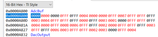
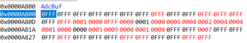
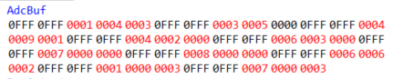
这是我有的代码 、从实验室中复制和粘贴、我不在乎它、因为它不会影响我想添加的功能(除了 ADC 的读取)
//#############################################################################
//
// FILE: lab_main.c
//
// TITLE: adc lab
//
// C2K ACADEMY URL: dev.ti.com/.../node
//
//! \addtogroup academy_lab_list
//! <h1> Using Analog Subsystems Lab - Sysconfig </h1>
//!
//! The objective of this lab exercise is to become familiar with the
//! programming and operation of the on-chip analog-to-digital converter (ADC).
//! The microcontroller (MCU) will be setup to sample a single ADC input
//! channel at a prescribed sampling rate and store the conversion result in a
//! circular memory buffer. In the second part of this lab exercise, the
//! digital-to-analog converter (DAC) will be explored.
//!
//! \b External \b Connections \n
//!  - Refer to Academy Lab instruction for exact pin for your device/board
//!
//! \b Watch \b Variables \n
//!  - None.
//!
//#############################################################################
// $Copyright:
// Copyright (C) 2022 Texas Instruments Incorporated - http://www.ti.com
//
// Redistribution and use in source and binary forms, with or without
// modification, are permitted provided that the following conditions
// are met:
//
//   Redistributions of source code must retain the above copyright
//   notice, this list of conditions and the following disclaimer.
//
//   Redistributions in binary form must reproduce the above copyright
//   notice, this list of conditions and the following disclaimer in the
//   documentation and/or other materials provided with the
//   distribution.
//
//   Neither the name of Texas Instruments Incorporated nor the names of
//   its contributors may be used to endorse or promote products derived
//   from this software without specific prior written permission.
//
// THIS SOFTWARE IS PROVIDED BY THE COPYRIGHT HOLDERS AND CONTRIBUTORS
// "AS IS" AND ANY EXPRESS OR IMPLIED WARRANTIES, INCLUDING, BUT NOT
// LIMITED TO, THE IMPLIED WARRANTIES OF MERCHANTABILITY AND FITNESS FOR
// A PARTICULAR PURPOSE ARE DISCLAIMED. IN NO EVENT SHALL THE COPYRIGHT
// OWNER OR CONTRIBUTORS BE LIABLE FOR ANY DIRECT, INDIRECT, INCIDENTAL,
// SPECIAL, EXEMPLARY, OR CONSEQUENTIAL DAMAGES (INCLUDING, BUT NOT
// LIMITED TO, PROCUREMENT OF SUBSTITUTE GOODS OR SERVICES; LOSS OF USE,
// DATA, OR PROFITS; OR BUSINESS INTERRUPTION) HOWEVER CAUSED AND ON ANY
// THEORY OF LIABILITY, WHETHER IN CONTRACT, STRICT LIABILITY, OR TORT
// (INCLUDING NEGLIGENCE OR OTHERWISE) ARISING IN ANY WAY OUT OF THE USE
// OF THIS SOFTWARE, EVEN IF ADVISED OF THE POSSIBILITY OF SUCH DAMAGE.
// $
//#############################################################################


//
// Included Files
//
#include "board.h"

//
// Global variables and definitions
//
#define ADC_BUF_LEN         50
uint16_t DEBUG_TOGGLE = 1;    // Used for real-time mode
uint16_t AdcBuf[ADC_BUF_LEN];  // ADC buffer allocation

#ifdef DACB_BASE
uint16_t DacOutput;
uint16_t DacOffset;
uint16_t SINE_ENABLE = 0;

// quadrature look-up table: contains 4 quadrants of sinusoid data points
#define SINE_PTS 25
int QuadratureTable[SINE_PTS] = {
        0x0000,         // [0]  0.0
        0x1FD4,         // [1]  14.4
        0x3DA9,         // [2]  28.8
        0x579E,         // [3]  43.2
        0x6C12,         // [4]  57.6
        0x79BB,         // [5]  72.0
        0x7FBE,         // [6]  86.4
        0x7DBA,         // [7]  100.8
        0x73D0,         // [8]  115.2
        0x629F,         // [9]  129.6
        0x4B3B,         // [10] 144.0
        0x2F1E,         // [11] 158.4
        0x100A,         // [12] 172.8
        0xEFF6,         // [13] 187.2
        0xD0E2,         // [14] 201.6
        0xB4C5,         // [15] 216.0
        0x9D61,         // [16] 230.4
        0x8C30,         // [17] 244.8
        0x8246,         // [18] 259.2
        0x8042,         // [19] 273.6
        0x8645,         // [20] 288.0
        0x93EE,         // [21] 302.4
        0xA862,         // [22] 316.8
        0xC257,         // [23] 331.2
        0xE02C          // [24] 345.6
        };
#endif

//
// Function Declarations
//
void initEPWM3(void);
__interrupt void INT_myADCA_1_ISR(void);
__interrupt void epwm3ISR(void);
//
// Main
//
void main(void)
{
    // CPU Initialization
    Device_init();
    Interrupt_initModule();
    Interrupt_initVectorTable();

    // Configure the GPIOs/ADC/PWM through SysConfig generated files
    Board_init();

    // Enable global interrupts and real-time debug
    EINT;
    ERTM;

    // Main Loop
    while(1){}

}

interrupt void INT_myADCA_1_ISR(void)
{
    static uint16_t *AdcBufPtr = AdcBuf;
    uint16_t LED_count = 0;

    // Read the ADC Result
    *AdcBufPtr++ = ADC_readResult(myADCA_RESULT_BASE, myADCA_SOC0);

    // Brute Force the circular buffer
    if (AdcBufPtr == (AdcBuf + ADC_BUF_LEN))
    {
        AdcBufPtr = AdcBuf;
    }

    // Toggle the pin
    if(DEBUG_TOGGLE == 1)
    {
        GPIO_togglePin(myGPIOToggle);
    }


#ifdef DACB_BASE
    // Write to DAC-B to create input to ADC-A0
    static uint16_t iQuadratureTable = 0;        // Quadrature table index

    if(SINE_ENABLE == 1)
    {
        DacOutput = DacOffset + ((QuadratureTable[iQuadratureTable++] ^ 0x8000) >> 5);
    }
    else
    {
        DacOutput = DacOffset;
    }
    if(iQuadratureTable > (SINE_PTS - 1))        // Wrap the index
    {
        iQuadratureTable = 0;
    }
    DAC_setShadowValue(myDACB_BASE, DacOutput);
#endif

    Interrupt_clearACKGroup(INT_myADCA_1_INTERRUPT_ACK_GROUP);
    ADC_clearInterruptStatus(myADCA_BASE, ADC_INT_NUMBER1);
} // End of ADC ISR


//
// End of File
//
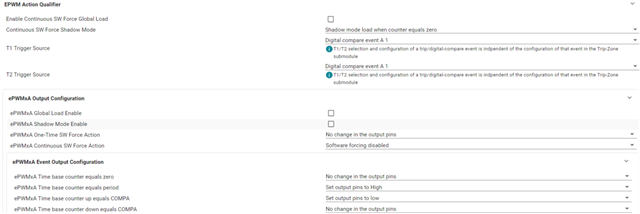
我将通过 SysConfig 配置系统的不同元件
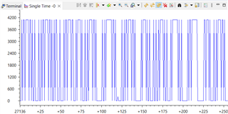
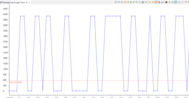
-在第一种情况下(方波信号5kHz,触发 PWM ADC 25kHz):
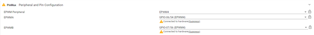
- 使用此设置的 myEPWM4 (使用 PWM 生成的方波信号):
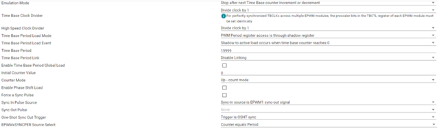

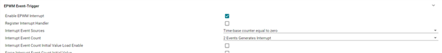
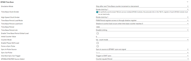
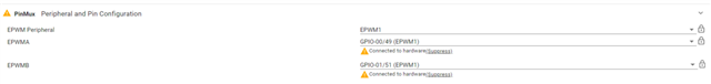
- 使用此设置的 myEPWM1 (ADC 触发):
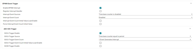
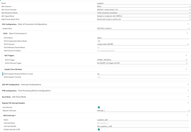
- 采用此设置的 ADC:
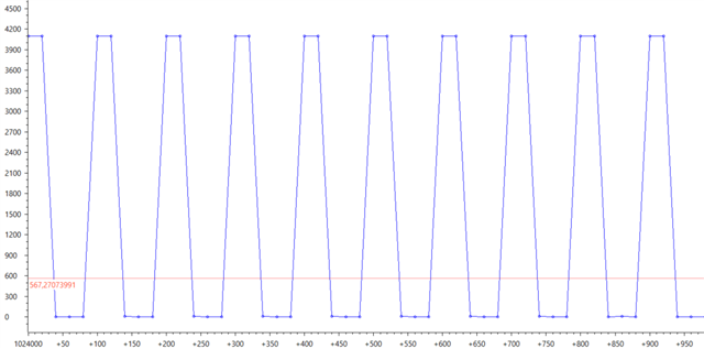
从示波器上可以看到、它们由5kHz 的 PWM 和 ADC 的触发 PWM (在中断 ADC 处理程序中切换、在代码中切换)切换的切换引脚(见代码)生成方波形、在高和低之间切换(在中断 ADC 处理程序中切换、见代码) 约为25kHz。
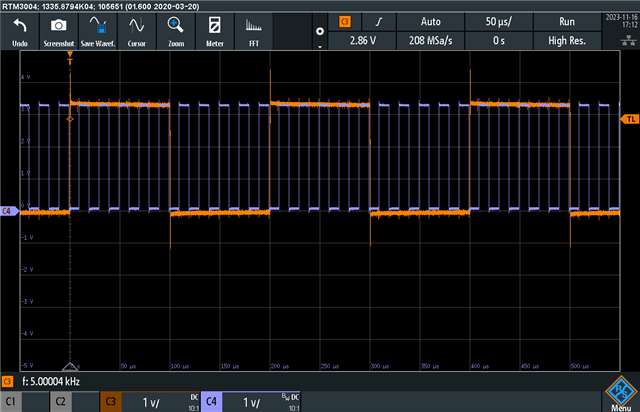
如图所示、转换的结果为:
合理的。
现在、当我 从 ADC 饱和中更改"SOC0采样窗口[SYSCLK 计数]"或从 ADC 的 PWM 触发器中更改"时基周期"时、ADC 讲座会非常糟糕、没有任何意义。
我将向您展示更多示例:
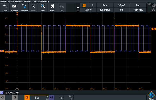
-案例2 ,与第1个示例相同,但将 SOC0采样窗口[SYSCLK 计数]从10更改为200。 ADC 的结果与第一种情况中的结果非常相似(如果更改该参数、我不知道为什么无法获得更多或更少的样本)
-案例3: 与第1个示例相同,但将 ADC 时钟预分频器更 改为 ADCCLK= CLKINPUT/2。 ADC 的结果与第一种情况中的结果
-案例4:与第一个示例相同,但将时基周期更改为999 (第一个扩展量的一半)。 在这种情况下、ADC 结果很糟糕、没有道理(方波输入信号保持不变)
ADC 结果会始终在0和1之间变化、没有任何检测
-案例6:与案例5相同、但使用时基周期1449、结果相同:
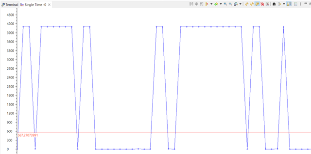
-案例6: 与第一个示例相同,但将时基周期更改为3999 (第一个示例的两倍)。 在这种情况下、ADC 结果又很糟糕、没有意义(方波输入信号保持不变)
我想知道的是如何从 ADC 获得更多测量点、以及是否可以通过修改 PWM 触发器或其他方法来实现。 但我想比第一个示例更准确地查看5kHz 信号、我不知道如何操作。
我希望你能帮助我,提前非常感谢你。
佩德罗