This thread has been locked.

If you have a related question, please click the "Ask a related question" button in the top right corner. The newly created question will be automatically linked to this question.

[参考译文] TMS320F2800137:F2800137问题

Guru**** 657930 points
请注意,本文内容源自机器翻译,可能存在语法或其它翻译错误,仅供参考。如需获取准确内容,请参阅链接中的英语原文或自行翻译。

https://e2e.ti.com/support/microcontrollers/c2000-microcontrollers-group/c2000/f/c2000-microcontrollers-forum/1295562/tms320f2800137-f2800137-problems

器件型号:TMS320F2800137

你好,专家!

我有两个问题需要询问:

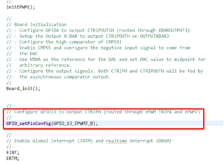
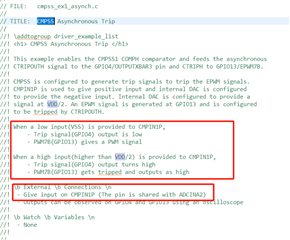
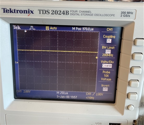
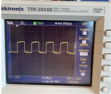
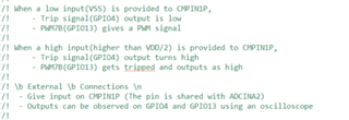
首先:在 TMS320F2800137LAUNCHXL 开发板_  ex1_asynch  演示上运行 cmpss、按照下图中的提示接地或将 ADCINA2连接至3.3V 电压。 PWM7B (GPIO13)没有 PWM 信号输出。 我可以问问、实现这个演示函数是什么以及如何实现的?

其次,关于交流电压环路 PI 算法,贵公司有很多 PI 算法功能,如下: DCL_ RunPI_ C1 (), DCL_ RunPI_ C1 (), DCL_ RunPI_ C2 (), DCL_ RunPI_ C3 (), DCL_ RunPI_ C4 (), DCL_ RunPI_ C5 (), DCL_ RunPI_(); 我想问一下、哪种比较是交流电压环路?

此致!

  • 请注意,本文内容源自机器翻译,可能存在语法或其它翻译错误,仅供参考。如需获取准确内容,请参阅链接中的英语原文或自行翻译。

    尊敬的 Yong:

    感谢节假日导致响应延迟、对此深表歉意。  

    我已将此主题传递给其他器件专家、他们可以对您的第一个问题给出具体的答案、但现在我可以回答第二个问题。

    您可以将任何 PI 配置用于您认为合适的电压环路、以下是针对每个 PI 配置的指定代码名称。

    DCL_runpi_c1:串联配置(C)

    DCL_runpi_C2:串联配置(ASM)

    DCL_runPI_C3:并行配置(C)

    DCL_runPI_C3:并行配置(ASM)

    DCL_runPI_C5:具有增强型反饱和功能的并行(C)

    DCL_runPI_C6:串联带 Tustin 积分器(C)

    DCL_runPI_C7:串联带 Tustin 积分器(ASM)

    建议使用该实现的汇编版本、如需更多信息、请参阅 DCL 用户指南。

    此致!

    王森


  • 请注意,本文内容源自机器翻译,可能存在语法或其它翻译错误,仅供参考。如需获取准确内容,请参阅链接中的英语原文或自行翻译。
    首先:在 TMS320F2800137LAUNCHXL 开发板上运行 cmpss _  ex1_asynch  演示、按照下图中的提示接地或将 ADCINA2连接到3.3V 电压。 PWM7B (GPIO13)没有 PWM 信号输出。 我可以问什么以及如何实现此演示功能吗?

    尊敬的 Yong:

    在本例中、为了输出 ePWM 输出、您需要配置 ePWM 输出引脚。 替换为以下代码。

    请告诉我、这是否可以解决该问题:

    //
    //
    // EPWM7_A - GPIO Settings
    //
    #define GPIO_PIN_EPWM7_A 28
    #define myEPWM7_EPWMA_GPIO 28
    #define myEPWM7_EPWMA_PIN_CONFIG GPIO_28_EPWM7_A
    //
    // EPWM7_B - GPIO Settings
    //
    #define GPIO_PIN_EPWM7_B 29
    #define myEPWM7_EPWMB_GPIO 29
    #define myEPWM7_EPWMB_PIN_CONFIG GPIO_29_EPWM7_B
    
    GPIO_setPinConfig(myEPWM7_EPWMA_PIN_CONFIG);
    // AGPIO -> GPIO mode selected
    GPIO_setAnalogMode(28, GPIO_ANALOG_DISABLED);
    GPIO_setPadConfig(myEPWM7_EPWMA_GPIO, GPIO_PIN_TYPE_STD);
    GPIO_setQualificationMode(myEPWM7_EPWMA_GPIO, GPIO_QUAL_SYNC);
    
    GPIO_setPinConfig(myEPWM7_EPWMB_PIN_CONFIG);
    GPIO_setPadConfig(myEPWM7_EPWMB_GPIO, GPIO_PIN_TYPE_STD);
    GPIO_setQualificationMode(myEPWM7_EPWMB_GPIO, GPIO_QUAL_SYNC);

    我将就此提交一个 JIRA 请求单、因为应该已经配置好了该请求单、对于产生的任何混淆深表歉意、感谢您提请我们注意!

    此致!

    马瑞安

  • 请注意,本文内容源自机器翻译,可能存在语法或其它翻译错误,仅供参考。如需获取准确内容,请参阅链接中的英语原文或自行翻译。

    你好, 专家!

    PWM 中例程配置的引脚13;

    我根据您的指示进行了修改、但我无法完成实验现象

    此致

  • 请注意,本文内容源自机器翻译,可能存在语法或其它翻译错误,仅供参考。如需获取准确内容,请参阅链接中的英语原文或自行翻译。

    也许我没有清楚地表达自己!

    我使用 cmpss_ ex1_asynch 演示来测试 CMPSS 和 XBAR 性能、 CMPIN1P (ADCINA2)具有3.3V 或0V 的输入、PWM7B (GPIO13)没有脉冲输出

  • 请注意,本文内容源自机器翻译,可能存在语法或其它翻译错误,仅供参考。如需获取准确内容,请参阅链接中的英语原文或自行翻译。

    尊敬的 Yong:

    抱歉、ePWM7B 或 GPIO13不工作。 您能否选择任何其他具有不同 GPIO 输出的 EPWM 基础、例如 ePWM6? 请告诉我这是否有效、我们可以在将来的版本中进行修复。 为困惑道歉。

    此致!

    马瑞安

  • 请注意,本文内容源自机器翻译,可能存在语法或其它翻译错误,仅供参考。如需获取准确内容,请参阅链接中的英语原文或自行翻译。

    //#############################################################################
    //
    // FILE:   cmpss_ex1_asynch.c
    //
    // TITLE:  CMPSS Asynchronous Trip
    //
    //! \addtogroup driver_example_list
    //! <h1> CMPSS Asynchronous Trip </h1>
    //!
    //! This example enables the CMPSS1 COMPH comparator and feeds the asynchronous
    //! CTRIPOUTH signal to the GPIO4/OUTPUTXBAR3 pin and CTRIPH to GPIO13/EPWM7B.
    //!
    //! CMPSS is configured to generate trip signals to trip the EPWM signals.
    //! CMPIN1P is used to give positive input and internal DAC is configured 
    //! to provide the negative input. Internal DAC is configured to provide a
    //! signal at VDD/2. An EPWM signal is generated at GPIO13 and is configured
    //! to be tripped by CTRIPOUTH.
    //!
    //! When a low input(VSS) is provided to CMPIN1P,
    //!     - Trip signal(GPIO4) output is low
    //!     - PWM7B(GPIO13) gives a PWM signal
    //!
    //! When a high input(higher than VDD/2) is provided to CMPIN1P,
    //!     - Trip signal(GPIO4) output turns high
    //!     - PWM7B(GPIO13) gets tripped and outputs as high
    //!
    //! \b External \b Connections \n
    //!  - Give input on CMPIN1P (The pin is shared with ADCINA2)
    //!  - Outputs can be observed on GPIO4 and GPIO13 using an oscilloscope
    //!
    //! \b Watch \b Variables \n
    //!  - None
    //!
    //
    //#############################################################################
    //
    //
    // $Copyright:
    // Copyright (C) 2023 Texas Instruments Incorporated - http://www.ti.com/
    //
    // Redistribution and use in source and binary forms, with or without 
    // modification, are permitted provided that the following conditions 
    // are met:
    // 
    //   Redistributions of source code must retain the above copyright 
    //   notice, this list of conditions and the following disclaimer.
    // 
    //   Redistributions in binary form must reproduce the above copyright
    //   notice, this list of conditions and the following disclaimer in the 
    //   documentation and/or other materials provided with the   
    //   distribution.
    // 
    //   Neither the name of Texas Instruments Incorporated nor the names of
    //   its contributors may be used to endorse or promote products derived
    //   from this software without specific prior written permission.
    // 
    // THIS SOFTWARE IS PROVIDED BY THE COPYRIGHT HOLDERS AND CONTRIBUTORS 
    // "AS IS" AND ANY EXPRESS OR IMPLIED WARRANTIES, INCLUDING, BUT NOT 
    // LIMITED TO, THE IMPLIED WARRANTIES OF MERCHANTABILITY AND FITNESS FOR
    // A PARTICULAR PURPOSE ARE DISCLAIMED. IN NO EVENT SHALL THE COPYRIGHT 
    // OWNER OR CONTRIBUTORS BE LIABLE FOR ANY DIRECT, INDIRECT, INCIDENTAL, 
    // SPECIAL, EXEMPLARY, OR CONSEQUENTIAL DAMAGES (INCLUDING, BUT NOT 
    // LIMITED TO, PROCUREMENT OF SUBSTITUTE GOODS OR SERVICES; LOSS OF USE,
    // DATA, OR PROFITS; OR BUSINESS INTERRUPTION) HOWEVER CAUSED AND ON ANY
    // THEORY OF LIABILITY, WHETHER IN CONTRACT, STRICT LIABILITY, OR TORT 
    // (INCLUDING NEGLIGENCE OR OTHERWISE) ARISING IN ANY WAY OUT OF THE USE 
    // OF THIS SOFTWARE, EVEN IF ADVISED OF THE POSSIBILITY OF SUCH DAMAGE.
    // $
    //#############################################################################
    
    //
    // Included Files
    //
    #include "driverlib.h"
    #include "device.h"
    #include "board.h"
    
    //
    // Function Prototypes
    //
    void initEPWM(void);
    
    //
    // Main
    //
    void main(void)
    {
        //
        // Initialize device clock and peripherals
        //
        Device_init();
    
        //
        // Disable pin locks and enable internal pullups.
        //
        Device_initGPIO();
    
        //
        // Initialize PIE and clear PIE registers. Disables CPU interrupts.
        //
        Interrupt_initModule();
    
        //
        // Initialize the PIE vector table with pointers to the shell Interrupt
        // Service Routines (ISR).
        //
        Interrupt_initVectorTable();
    
        //
        // Set up ePWM7 to take CTRIPH as TRIP4 for its DC trip input
        //
        initEPWM();
    
        //
        // Board Initialization
        // - Configure GPIO4 to output CTRIPOUT1H (routed through XBAROUTPUT3)
        // - Setup the Output X-BAR to output CTRIPOUTH on OUTPUTXBAR3
        // - Configure the high comparator of CMPSS1
        // - Enable CMPSS and configure the negative input signal to come from
        //   the DAC
        // - Use VDDA as the reference for the DAC and set DAC value to midpoint for
        //   arbitrary reference.
        // - Configure the output signals. Both CTRIPH and CTRIPOUTH will be fed by
        //   the asynchronous comparator output.
        //
        Board_init();
        GPIO_setAnalogMode(13U, GPIO_ANALOG_DISABLED) // Fix needed for example to work properly
    
        //
        // Configure GPIO13 to output CTRIPH (routed through ePWM TRIP4 and ePWM7)
        //
        GPIO_setPinConfig(GPIO_13_EPWM7_B);
    
        //
        // Enable Global Interrupt (INTM) and realtime interrupt (DBGM)
        //
        EINT;
        ERTM;
    
        //
        // Loop indefinitely
        //
        while(1)
        {
            //
            // Trip flag is set when CTRIP signal is asserted
            //
            if((EPWM_getTripZoneFlagStatus(EPWM7_BASE) &
                EPWM_TZ_FLAG_OST) != 0U)
            {
                //
                // Wait for comparator CTRIP to de-assert
                //
                while((CMPSS_getStatus(CMPSS1_BASE) & CMPSS_STS_HI_FILTOUT) != 0U)
                {
                    ;
                }
    
                //
                // Clear trip flags
                //
                EPWM_clearTripZoneFlag(EPWM7_BASE, EPWM_TZ_INTERRUPT |
                                       EPWM_TZ_FLAG_OST);
            }
        }
    }
    
    //
    // initEPWM - Function to configure ePWM7 and the ePWM X-BAR to take CTRIPH as
    //            the DC trip input
    //
    void initEPWM(void)
    {
        //
        // Disable the ePWM time base clock before configuring the module
        //
        SysCtl_disablePeripheral(SYSCTL_PERIPH_CLK_TBCLKSYNC);
    
        //
        // Set the time base clock prescalers to /1
        //
        EPWM_setClockPrescaler(EPWM7_BASE, EPWM_CLOCK_DIVIDER_1,
                               EPWM_HSCLOCK_DIVIDER_1);
    
        //
        // Initializing dummy values for ePWM counter and period
        //
        EPWM_setTimeBaseCounter(EPWM7_BASE, 0);
        EPWM_setTimeBasePeriod(EPWM7_BASE, 0xFFFF);
    
        //
        // Set-up compare
        //
        EPWM_setCounterCompareValue(EPWM7_BASE, EPWM_COUNTER_COMPARE_B, 0x8000);
    
        //
        // Set actions
        //
        EPWM_setActionQualifierAction(EPWM7_BASE,
                                      EPWM_AQ_OUTPUT_B,
                                      EPWM_AQ_OUTPUT_HIGH,
                                      EPWM_AQ_OUTPUT_ON_TIMEBASE_UP_CMPB);
    
        EPWM_setActionQualifierAction(EPWM7_BASE,
                                      EPWM_AQ_OUTPUT_B,
                                      EPWM_AQ_OUTPUT_LOW,
                                      EPWM_AQ_OUTPUT_ON_TIMEBASE_ZERO);
    
        //
        // Configure ePWM7B to output high on TZB TRIP
    
        //
        EPWM_setTripZoneAction(EPWM7_BASE, EPWM_TZ_ACTION_EVENT_TZB,
                               EPWM_TZ_ACTION_HIGH);
    
        //
        // Trigger event when DCBH is high
        //
        EPWM_setTripZoneDigitalCompareEventCondition(EPWM7_BASE,
                                                     EPWM_TZ_DC_OUTPUT_B1,
                                                     EPWM_TZ_EVENT_DCXH_HIGH);
    
        //
        // Configure DCBH to use TRIP4 as an input
        //
        EPWM_enableDigitalCompareTripCombinationInput(EPWM7_BASE,
                                                      EPWM_DC_COMBINATIONAL_TRIPIN4,
                                                      EPWM_DC_TYPE_DCBH);
    
        //
        // Enable DCB as OST
        //
        EPWM_enableTripZoneSignals(EPWM7_BASE, EPWM_TZ_SIGNAL_DCBEVT1);
    
        //
        // Configure the DCB path to be unfiltered and asynchronous
        //
        EPWM_setDigitalCompareEventSource(EPWM7_BASE,
                                          EPWM_DC_MODULE_B,
                                          EPWM_DC_EVENT_1,
                                          EPWM_DC_EVENT_SOURCE_ORIG_SIGNAL);
    
        //
        // Sync the ePWM time base clock
        //
        SysCtl_enablePeripheral(SYSCTL_PERIPH_CLK_TBCLKSYNC);
    
        //
        // Configure TRIP4 to be CTRIP1H using the ePWM X-BAR
        //
        XBAR_setEPWMMuxConfig(XBAR_TRIP4, XBAR_EPWM_MUX00_CMPSS1_CTRIPH);
        XBAR_enableEPWMMux(XBAR_TRIP4, XBAR_MUX00);
    
    
        //
        // Clear trip flags
        //
        EPWM_clearTripZoneFlag(EPWM7_BASE, EPWM_TZ_INTERRUPT |
                               EPWM_TZ_FLAG_OST);
    
        //
        // Put the time base counter into up-count mode
        //
        EPWM_setTimeBaseCounterMode(EPWM7_BASE, EPWM_COUNTER_MODE_UP);
    }

  • 请注意,本文内容源自机器翻译,可能存在语法或其它翻译错误,仅供参考。如需获取准确内容,请参阅链接中的英语原文或自行翻译。

    好的,我可以使用 PWM6输出 ePWM 信号、

    但是、对于 CMPIN1P (ADCINA2) 3.3V 或0V 的输入、PWM6不输出高电平。

    CMSS 模块看起来不会通过 Xbar 信号跳闸。

    您自己的

  • 请注意,本文内容源自机器翻译,可能存在语法或其它翻译错误,仅供参考。如需获取准确内容,请参阅链接中的英语原文或自行翻译。

    需要聘请 CMPSS 专家来解决这个问题、我们将在明天提供 EOD 更新。  

    此致!

    马瑞安

  • 请注意,本文内容源自机器翻译,可能存在语法或其它翻译错误,仅供参考。如需获取准确内容,请参阅链接中的英语原文或自行翻译。

    好的、期待您的好消息

    谢谢

  • 请注意,本文内容源自机器翻译,可能存在语法或其它翻译错误,仅供参考。如需获取准确内容,请参阅链接中的英语原文或自行翻译。

    尊敬的 Yong:

    1) 1) 在该器件中、引脚 GPIO13与 ADC 引脚进行多路复用(引脚29是 AGPIO)、 您需要将其定义为 GPIO。 为此、您需要使用函数 GPIO_setAnalogMode (13U、GPIO_analog_disabled)。  您应该 在 cmpss_ex1_asynch.c 中 Board_init()之后添加它。  

    2) 2)我尝试了最新的代码 Ryan 发送给您 EPWM6_B 路由到 输出。

    在这里、您可以看到当我将 A2连接到3.3V 和0时的结果:

    如果您有任何问题、敬请告知。

    此致、

    哈迪

  • 请注意,本文内容源自机器翻译,可能存在语法或其它翻译错误,仅供参考。如需获取准确内容,请参阅链接中的英语原文或自行翻译。

    谢谢你,Hadi!

    使用 GPIO_setAnalogMode (13U、GPIO_analog_disabled) 实施此实验;

    但是、Ryan 发送给我的代码仍然没有实现示波器的显示效果。  我想知道是否有必要重新配置 CMPSS 和 Xbar 模块

  • 请注意,本文内容源自机器翻译,可能存在语法或其它翻译错误,仅供参考。如需获取准确内容,请参阅链接中的英语原文或自行翻译。

    尊敬的 Yong:

    您能否尝试从现有的示例开始、重新导入该示例并添加  GPIO_setAnalogMode (13U、GPIO_analog_disabled);行。

    这样示例就可以按预期工作。

    此致!

    马瑞安

  • 请注意,本文内容源自机器翻译,可能存在语法或其它翻译错误,仅供参考。如需获取准确内容,请参阅链接中的英语原文或自行翻译。

    是的、我已使此示例按预期工作

    也许我没有足够清楚地表达自己;

    我的意思是、您提供的代码无法正常使用(代码由 PWM6输出)

    感谢你的评分  

    最佳

  • 请注意,本文内容源自机器翻译,可能存在语法或其它翻译错误,仅供参考。如需获取准确内容,请参阅链接中的英语原文或自行翻译。

    尊敬的 Yong:

    感谢您的澄清、我将参考我们的示例并添加 Set analogemode driverlib 函数来更新我的答复。

    完成此操作后、您是否可以将该主题标记为已解决?

    谢谢!

  • 请注意,本文内容源自机器翻译,可能存在语法或其它翻译错误,仅供参考。如需获取准确内容,请参阅链接中的英语原文或自行翻译。

    确定

    此致