This thread has been locked.

If you have a related question, please click the "Ask a related question" button in the top right corner. The newly created question will be automatically linked to this question.

[参考译文] TMS320F280025C:看门狗问题:不及#39;t set reset

Guru**** 666710 points
Other Parts Discussed in Thread: UNIFLASH
请注意,本文内容源自机器翻译,可能存在语法或其它翻译错误,仅供参考。如需获取准确内容,请参阅链接中的英语原文或自行翻译。

https://e2e.ti.com/support/microcontrollers/c2000-microcontrollers-group/c2000/f/c2000-microcontrollers-forum/1298871/tms320f280025c-watchdog-problem-don-t-set-reset

器件型号:TMS320F280025C
主题中讨论的其他器件:C2000WAREUNIFLASH

您好!

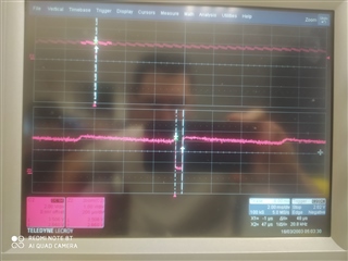
看门狗复位有问题、已将其配置为触发目标复位。 在初始化阶段、我打开和关闭一个 Led、以可视化方式显示我在此阶段的通道。 重置时间设为419ms。 我还为我的应用程序配置了 ADC 中断、但当我没有将计数器复位时、我可以看到 RST 引脚变为0、这证明复位已发生(50µs 处于低电平状态的持续时间)。 然而,我不重新访问我的初始化 tootgle led ,所以重新启动不起作用。 因此、我缺少一种理解元素。 可以帮帮我吗?

在另一个测试阶段,当我使用 ServiceDog ()函数重置主循环中的计数器时,我只执行一次中断,但仍然在主循环中停止。 计数器会使 WDCNTR 递增、并在 servicedog 函数更新 WDKEY 寄存器时复位为0。 这也很奇怪。 问题出在哪呢?

在这里、我的

void init_watchdog(void)
{
    // Reset the watchdog counter
    ServiceDog();
    // Configure timings to set reset for software watchdog, PREDIVCLK = INTOSC1 / Pre-divider and WDCLK = PREDIVCLK / Prescaler
    // With INTOSC1 = 10 MHz, WDCLK = 2441.4 / 4 = 610.35 Hz, 1 tick -> 1/610.35 = 1.638ms and counter is on 8 bits so 256 ticks -> 419 ms
    // XRS pin is low for 512 OSCCLK cycles so 512 * (1 / 10.10^6) = 51µs
    // Pre-divider = 4096
    EALLOW;
    //WdRegs.WDCR.bit.WDCHK = 0x5
    //WdRegs.WDCR.bit.WDPRECLKDIV = 0x3
    // Prescaler = 4
    //WdRegs.WDCR.bit.WDPS = 0x3
    WdRegs.WDCR.all = 0x032B;

    // Counter expiration triggers a reset, this is the default state on the power-up and after any system reset.
    // Write to the whole SCSR register to avoid clearing WDOVERRIDE bit
    WdRegs.SCSR.all = 0;
    EDIS;
}
#pragma CODE_SECTION(adc_isr, ".TI.ramfunc");
__interrupt void adc_isr()
{
    EALLOW;


    // Clear INT1 flag.
    AdccRegs.ADCINTFLGCLR.bit.ADCINT1 = 1;
    // Check if overflow has occurred.
    if(AdccRegs.ADCINTOVF.bit.ADCINT1 == 1)
    {
        // Clear INT1 overflow flag
        AdccRegs.ADCINTOVFCLR.bit.ADCINT1 = 1;
        // Clear INT1 flag
        AdccRegs.ADCINTFLGCLR.bit.ADCINT1 = 1;
    }
    // Acknowledge PIE group 1 to receive more interrupts from this group.
    PieCtrlRegs.PIEACK.bit.ACK1 = 1;
    EDIS;
}
 代码:
int main(void)
{
    // PLL initialization and load the code in flash memory by the pre defined symbols include in Project -> Properties -> Pre defined symbols _FLASH to execute the flash initialization.\n
    // MemCpy to copy the code in RAM.
    InitSysCtrl();

    // Read reset cause register to know which reset is the cause (external or software watchdog)
    if(CpuSysRegs.RESC.bit.WDRSn == true)
    {
        // Indicates reset cause : software
        reset_status = 1;
        // Reset flag in cause register
        CpuSysRegs.RESCCLR.bit.WDRSn = true;
    }
    else if(CpuSysRegs.RESC.bit.XRSn == true)
    {
        // Indicates reset cause : external watchdog
        reset_status = 2;
        // Reset flag in cause register
        CpuSysRegs.RESCCLR.bit.XRSn = true;
    }

    // GPIO initialization
    gpio_init();

    GpioCtrlRegs.GPAPUD.bit.GPIO8 = 1;          // Disable the pullup on GPIO8
    GpioCtrlRegs.GPADIR.bit.GPIO8 = 1;          // GPIO8 = output
    GpioCtrlRegs.GPAODR.bit.GPIO8 = 0;          // Normal output not open drain
    GpioCtrlRegs.GPAQSEL1.bit.GPIO8 = 0;        // Synchronous
    GpioCtrlRegs.GPAMUX1.bit.GPIO8 = 0;         // GPIO8 = GPIO8
    GpioDataRegs.GPASET.bit.GPIO8 = 0;          // Force output data latch to high level.
    GpioDataRegs.GPADAT.bit.GPIO8 = 0;          // Set output value

    GpioDataRegs.GPADAT.bit.GPIO8 = 1;          // Set output value
    DELAY_US(2000000);
    GpioDataRegs.GPADAT.bit.GPIO8 = 0;          // Set output value

    // Disable CPU interrupts.
    DINT;
    // Initialize the PIE control registers to their default value.
    InitPieCtrl();
    // Disable CPU interrupts and clear all cPU interrupt flags.
    IER = 0x0000;
    IFR = 0x0000;
    // Initialize the PIE vectors table with pointers to the shell Interrupt Service Routine.
    InitPieVectTable();

    // Authorize register access.
    EALLOW;
    // Mapping adc_isr function to ADCC_I NT interrupt.
    PieVectTable.ADCC1_INT = &adc_isr;
    // Lock register access.
    EDIS;

    // Authorize register access.
    EALLOW;
    // Mapping tripzone_isr function to EPWM1_TZ_INT interrupt.
    PieVectTable.EPWM1_TZ_INT = &tripzone_isr;
    // Lock register access.
    EDIS;

    // Enable group 1 interrupts for ADCC interrupt and WAKE interrupt.
    IER |= M_INT1;
    // Enable group2 interrupts for trip zone interrupt.
    IER |= M_INT2;
    // Enable the PIE block
    PieCtrlRegs.PIECTRL.bit.ENPIE = 1;
    // Enable PIE interrupt 1.3 for ADCC1 interrupt.
    PieCtrlRegs.PIEIER1.bit.INTx3 = 1;
    // Enable PIE interrupt 2.1 for EPWM1 trip zone interrupt.
    PieCtrlRegs.PIEIER2.bit.INTx1 = 1;

    // Read master/slave configuration pin to initialize PWM correctly with phase shift equal 60° between them
    if(GpioDataRegs.GPADAT.bit.GPIO12 == false)
    {
        uc_state_master_slave = MASTER;
        // EPWM initialization function.
        epwm_init_spwm_branch_u();
        epwm_init_spwm_branch_v();
        epwm_init_spwm_branch_w();
        // Configure synchronization signal : load program to uC1 firstly because uC2 need external synchronization
        epwm_synch_init();
    }
    else
    {
        uc_state_master_slave = SLAVE;
        epwm_init_spwm_branch_x();
        epwm_init_spwm_branch_y();
        epwm_init_spwm_branch_z();
    }
    // Software watchdog initialization
    init_watchdog();

    // Analog to Digital Converter initialization.
    adc_init();
    // Comparator subsytem initialization.
    // Fuel cell OVP and Battery OCP
    cmpss1_init();
    // Battery OVP and Mi_U peak current
    cmpss2_init();
    // Mi_W peak current
    cmpss3_init();
    // MI_V peak current
    cmpss4_init();
    // Configure trip zone for return driver (GPIOmux -> InputXbar -> Trip_zone -> Epwm_module)
    tz_driver_return_init();

    // CPUTimer2 is used for extern watchdog.
    init_cpu_timers(&CpuTimer2Regs);

    // CAN bus initialization
    can_init();
    // I2C bus initialization
    i2c_init();
    // Reset timer
    CpuTimer2Regs.TCR.bit.TRB = 1;

    // Enable Global interrupt INTM
    EINT;
    // Enable Global realtime interrupt DBGM
    ERTM;

    while(1)
    {
        // Extern watchdog (200ms)
        // Toggle pin for watchdog for WDI signal on TPS3823-33Q1
        level_wdi_watchdog_pin = !level_wdi_watchdog_pin;
        GpioDataRegs.GPADAT.bit.GPIO25 = level_wdi_watchdog_pin;
        extern_watchdog_meas.start_time = CpuTimer2Regs.TIM.all;

        // Reset the watchdog counter
        ServiceDog();

        extern_watchdog_meas.end_time = CpuTimer2Regs.TIM.all;
        // Measure main loop timing
        extern_watchdog_meas.timediff = extern_watchdog_meas.start_time - extern_watchdog_meas.end_time;
        // Reset timer
        CpuTimer2Regs.TCR.bit.TRB = 1;
    }
}

谢谢

达米恩

  • 请注意,本文内容源自机器翻译,可能存在语法或其它翻译错误,仅供参考。如需获取准确内容,请参阅链接中的英语原文或自行翻译。

    尊敬的 Damien:

    是否在 CCS 已连接的情况下运行测试? 如果是、则请注意在 CCS 连接后、器件引导作为仿真引导、您需要正确设置仿真引导、以便在复位后、器件引导至您的闪存应用。 请参阅器件 TRM 以了解有关仿真引导的详细信息。

    我不清楚第二个测试阶段中提到的问题。  写入密钥时、WDCNTR 将被重置、这是预期行为。 您能否通过指出具体的执行顺序来解释这个问题?

    维维克·辛格

  • 请注意,本文内容源自机器翻译,可能存在语法或其它翻译错误,仅供参考。如需获取准确内容,请参阅链接中的英语原文或自行翻译。

    您好、Vivek、

    连接未连接调试探针的情况下测试了这两种情况、问题仍然是相同的、引脚 XRS 上产生复位脉冲、但代码的初始化未重新执行、因为我的 LED 不会再次亮起现在、我在配置了 ADC 中断的情况下执行以下操作、配置看门狗的时间远大于 ISR。 尽管通过"Scripts"->EMU 引导模式选择"->"EMU 引导闪存"切换到了 EMU 引导闪存模式、但连接 CCS 后我仍然收到错误消息。

    如何重置 DSP 并再次使用 toggle led 运行初始化命令? 我已注释掉 main 中的 ServiceDog 函数、这样就不会重置计数器从而触发重置、对吧?

    当计数器使用定义的时钟达到256时、我想对目标进行简单的重置、并使用我的切换 LED 将此重置可视化。 是配置问题吗?

    谢谢

    达米恩

  • 请注意,本文内容源自机器翻译,可能存在语法或其它翻译错误,仅供参考。如需获取准确内容,请参阅链接中的英语原文或自行翻译。

    您好!

    尽管通过 Scripts 切换到 EMU 引导闪存模式,但当 CCS 已连接时,我仍收到错误消息-> EMU 引导模式选择-> EMU 引导闪存。

    什么是错误信息?

    当您在连接了调试器的情况下运行时,在复位后,代码执行在哪里被卡住了? 你为什么要这么做?"

    维维克·辛格

  • 请注意,本文内容源自机器翻译,可能存在语法或其它翻译错误,仅供参考。如需获取准确内容,请参阅链接中的英语原文或自行翻译。

    您好、Vivek、

    该错误可以在映像的前一条消息中看到、我认为它会损坏引导 ROM 存储器。 错误信息为"地址"0x3f4751处的中断、没有可用的调试信息、或者超出程序代码。" 它对应于 ESTOP0行、如果我按 F8以恢复、则它已经位于该行中。

    在这里你可以看到我的 cmd 文件:

    MEMORY
    {
       BOOT_RSVD		: origin = 0x00000002, length = 0x00000126
       RAMM0           	: origin = 0x00000128, length = 0x000002D6//2D8
       RAMM1            : origin = 0x00000400, length = 0x000003F8     /* on-chip RAM block M1 */
    // RAMM1_RSVD       : origin = 0x000007F8, length = 0x00000008 /* Reserve and do not use for code as per the errata advisory "Memory: Prefetching Beyond Valid Memory" */
       
    /* RAMLS4           : origin = 0x0000A000, length = 0x00000800
       RAMLS5           : origin = 0x0000A800, length = 0x00000800
       RAMLS6           : origin = 0x0000B000, length = 0x00000800
       RAMLS7           : origin = 0x0000B800, length = 0x00000800 */
    
       /* Combining all the LS RAMs */
       RAMLS4567        : origin = 0x0000A000, length = 0x00002000
       RAMGS0           : origin = 0x0000C000, length = 0x000007F8
    // RAMGS0_RSVD      : origin = 0x0000C7F8, length = 0x00000008 /* Reserve and do not use for code as per the errata advisory "Memory: Prefetching Beyond Valid Memory" */
    
       BOOTROM          : origin = 0x003F0000, length = 0x00008000
       BOOTROM_EXT      : origin = 0x003F8000, length = 0x00007FC0
       RESET            : origin = 0x003FFFC0, length = 0x00000002 //.reset is a standard section used by the compiler.  It contains the the address of the start of _c_int00 for C Code.
       
    #ifdef __TI_COMPILER_VERSION__
       #if __TI_COMPILER_VERSION__ >= 20012000
    GROUP {      /* GROUP memory ranges for crc/checksum of entire flash */
       #endif
    #endif
       BEGIN           	: origin = 0x085000, length = 0x000002 // origin = 0x080000
       /* Flash sectors */
       /* BANK 0 */
    // FLASHBANK0       : origin = 0x00080000, length = 0x0000FFF0
       //FLASH_BANK0_SEC0  : origin = 0x080002, length = 0x000FFE	/* on-chip Flash */
       //FLASH_BANK0_SEC1  : origin = 0x081000, length = 0x001000	/* on-chip Flash */
       //FLASH_BANK0_SEC2  : origin = 0x082000, length = 0x001000	/* on-chip Flash */
       //FLASH_BANK0_SEC3  : origin = 0x083000, length = 0x001000	/* on-chip Flash */
       FLASH_BANK0_SEC4  : origin = 0x084000, length = 0x001000		/* on-chip Flash */
       FLASH_BANK0_SEC5  : origin = 0x085008, length = 0x000FF8	/* on-chip Flash */
       FLASH_BANK0_SEC6  : origin = 0x086000, length = 0x001000	/* on-chip Flash */
       FLASH_BANK0_SEC7  : origin = 0x087000, length = 0x001000	/* on-chip Flash */
       FLASH_BANK0_SEC8  : origin = 0x088000, length = 0x001000	/* on-chip Flash */
       FLASH_BANK0_SEC9  : origin = 0x089000, length = 0x001000	/* on-chip Flash */
       FLASH_BANK0_SEC10 : origin = 0x08A000, length = 0x001000	/* on-chip Flash */
       FLASH_BANK0_SEC11 : origin = 0x08B000, length = 0x001000	/* on-chip Flash */
       FLASH_BANK0_SEC12 : origin = 0x08C000, length = 0x001000	/* on-chip Flash */
       FLASH_BANK0_SEC13 : origin = 0x08D000, length = 0x001000	/* on-chip Flash */
       FLASH_BANK0_SEC14 : origin = 0x08E000, length = 0x001000	/* on-chip Flash */
       FLASH_BANK0_SEC15 : origin = 0x08F000, length = 0x001000	/* on-chip Flash */
       //FLASH_BANK0_SEC5_6_7_8_9_10_11_12_13_14_15  : origin = 0x085008, length = 0x0AFF0 // origin = 0x085000
    // FLASH_BANK0_SEC15_RSVD     : origin = 0x08FFF0, length = 0x000010  /* Reserve and do not use for code as per the errata advisory "Memory: Prefetching Beyond Valid Memory" */
    #ifdef __TI_COMPILER_VERSION__
      #if __TI_COMPILER_VERSION__ >= 20012000
    }  crc(_table_name, algorithm=C28_CHECKSUM_16)
      #endif
    #endif
    
    }
    
    
    SECTIONS
    {
       codestart        : > BEGIN, ALIGN(8)
       // Executable code and constants.
       .text            : >> FLASH_BANK0_SEC5 | FLASH_BANK0_SEC6 | FLASH_BANK0_SEC7 | FLASH_BANK0_SEC8 | FLASH_BANK0_SEC9 | FLASH_BANK0_SEC10 | FLASH_BANK0_SEC11 | FLASH_BANK0_SEC12 | FLASH_BANK0_SEC13 | FLASH_BANK0_SEC14 | FLASH_BANK0_SEC15,   ALIGN(8)
       // Tables for explicitly initialized  global and static variables.
       .cinit           : > FLASH_BANK0_SEC4,  ALIGN(8)
       // Jump tables for large switch statements.
       .switch          : > FLASH_BANK0_SEC4,  ALIGN(8)
       .reset           : > RESET,                  TYPE = DSECT /* not used, */
    	// In stack memory
       .stack           : > RAMM1
    	// Table of constructors to be called at startup (EABI output format only), it is the case, see project options.
       .init_array      : > FLASH_BANK0_SEC4,  ALIGN(8)
       // Global and static variables (EABI output format only)
       .bss             : > RAMLS4567
       .bss:output      : > RAMLS4567
       .bss:cio         : > RAMGS0
       // Global and static variables that are explicitly initialized and contain string literals.
       .const           : > FLASH_BANK0_SEC4,  ALIGN(8)
       // Global and static non-const variables that are explicitly initialized.
       .data            : > RAMLS4567
       // Memory for malloc functions (EABI output format only).
       .sysmem          : > RAMLS4567
    
        ramgs0 : > RAMGS0
    
        /*  Allocate IQ math areas: */
       IQmath           : > RAMLS4567
       IQmathTables     : > RAMLS4567
    
      .TI.ramfunc      : LOAD = FLASH_BANK0_SEC5 | FLASH_BANK0_SEC6 | FLASH_BANK0_SEC7 | FLASH_BANK0_SEC8 | FLASH_BANK0_SEC9 | FLASH_BANK0_SEC10 | FLASH_BANK0_SEC11 | FLASH_BANK0_SEC12 | FLASH_BANK0_SEC13 | FLASH_BANK0_SEC14 | FLASH_BANK0_SEC15,
                      RUN = RAMGS0,
                      LOAD_START(RamfuncsLoadStart),
                      LOAD_SIZE(RamfuncsLoadSize),
                      LOAD_END(RamfuncsLoadEnd),
                      RUN_START(RamfuncsRunStart),
                      RUN_SIZE(RamfuncsRunSize),
                      RUN_END(RamfuncsRunEnd),
                      ALIGN(8)
    
       /* crc/checksum section configured as COPY section to avoid including in executable */
       .TI.memcrc          : type = COPY
    
    }
    /*
    //===========================================================================
    // End of file.
    //===========================================================================
    */
    

  • 请注意,本文内容源自机器翻译,可能存在语法或其它翻译错误,仅供参考。如需获取准确内容,请参阅链接中的英语原文或自行翻译。

    正如我说过的、如果我不在调试模式下运行并注释掉 ServiceDog 行、以免将计数器重置为0并触发重置、嗯、我不会观察到任何内容(没有重置、我的切换 LED 不会再次执行)。

  • 请注意,本文内容源自机器翻译,可能存在语法或其它翻译错误,仅供参考。如需获取准确内容,请参阅链接中的英语原文或自行翻译。

    连接调试器后、请遵循以下顺序。

    连接至 CCS。

    通过脚本更改 EMU 引导设置。  

    从 CCS 发出复位命令  

    单击运行

    就会看到这个错误。 lood 使用加载符号选项更改 BootROM 符号。 引导 ROM 符号文件可在" \libraries\boot_rom\f28002x\rev0\rom_sources\CCS_files\CPU\Release"。  

    通过执行此操作、您应该能够找出阻塞了位置代码执行的位置。

    维维克·辛格

  • 请注意,本文内容源自机器翻译,可能存在语法或其它翻译错误,仅供参考。如需获取准确内容,请参阅链接中的英语原文或自行翻译。

    您好、Vivek、

    谢谢、我下周一要试一下、因为我现在正在接受培训

    达米恩

  • 请注意,本文内容源自机器翻译,可能存在语法或其它翻译错误,仅供参考。如需获取准确内容,请参阅链接中的英语原文或自行翻译。

    您好、Vivek、

    我测试了您的序列、但没有成功、我首先加载了我的可执行代码、然后在启动运行之前、我加载了 bootrom 符号文件(见照片)、并出现一个新的 CCS 错误(见照片)、地址为0x859ca、停止位置为(如果我没记错、则对应于闪存地址)。

    如果我关闭这个错误窗口并运行程序,那么我的代码就能正确执行(打开然后关闭),我在 cpu1brom_itrapISR ():函数中观察到一个停止。 软件的角度来看不会观察到复位我的代码也不会再次执行但是、引脚 XRS 上确实会出现复位脉冲(随附照片、低电平状态持续时间为48us)。 这对我来说似乎是正确的。

    CCS 控制台上将显示一条错误消息:"在"D:/Projects/Boot_ROM/bootrom_f28002x/F28002x_ROM_dev_PG1.0/F28002x_ROM/bootROM/source/cpubrom_interrupts.c 中找不到源文件"。 找到文件或编辑源查找路径以包括其位置。"

    这条消息是什么意思? 为什么需要包含此文件? 这是我的问题的唯一根源吗?

    因为我不想、所以必须集成 driverlib 吗? 因为为了实现完美控制、我使用位域

    感谢您的帮助

    达米恩

  • 请注意,本文内容源自机器翻译,可能存在语法或其它翻译错误,仅供参考。如需获取准确内容,请参阅链接中的英语原文或自行翻译。

    您好!

    我首先加载了可执行代码,然后在启动运行之前,我加载了 bootrom 符号文件(见照片),但在地址0x859ca 处出现一个新的 CCS 错误(见照片)(如果我没有弄错,则该地址对应于闪存地址)。

    这仅仅意味着它无法定位源、因为您已加载 BootROM 符号。  

    如果我关闭此错误窗口并运行程序,然后我的代码正确执行(打开然后关闭),我在 cpu1brom_itrapISR ():

    在 CPU1BROM_ItrapISR ()中停止不好。 这意味着 CPU 提取了一些非法指令。 如果 CPU 尝试从非代码区域的位置执行、则可能会发生这种情况。 如果加载代码后、您复位了 CPU 并按照我提到的步骤操作、会发生什么情况。 并尝试运行?

    CCS 控制台上出现一条错误消息:"Can't find a source file at "D":/Projects/Boot_ROM/bootrom_f28002x/F28002x_ROM_dev_PG1.0/F28002x_ROM/bootROM/source/cpubrom_interrupts.c。 找到文件或编辑源查找路径以包括其位置。"

    这只是要求您定位引导 ROM 源文件。 这不是错误。  

    维维克·辛格

  • 请注意,本文内容源自机器翻译,可能存在语法或其它翻译错误,仅供参考。如需获取准确内容,请参阅链接中的英语原文或自行翻译。

    您好、Vivek、

    如果我在连接了调试器的情况下加载我的代码并复位 CPU (通过 Run->Reset->CPU Reset)、则 CCS 消息为"_system_post_cinit ()"(在 C:/...)。

    接下来、我将关闭此消息并尝试您提到的步骤:Scripts -> EMU boot mode select -> EMU boot flash 和 load symbols for boot ROM。

    我已经包含 cpubrom_ccs.asm、因为消息被设定为 Init_Boot。 因此、我在运行时会可视化 INIT、所有 bootROM 初始化地址都设置为0x3fxxxx 地址。 当我跳转至0x080000地址后、我的存储器映射中没有这个地址、这很奇怪? 在我跳转至0x08635f 地址后、知道根据我的映射、开始位于地址0x085000、为什么我不看到这个通道? 接下来、我继续并在地址0x00c057中中断、其中没有任何信息?

    知道如果不执行您的操作、我的代码仍然会执行、因此整个初始化阶段必须正确完成吧? 这是一个通过汇编器文件的路径链接到调试器模式的问题。 问题是否与我的映射(附后)关联?

    谢谢

    达米恩

    MEMORY
    {
       BOOT_RSVD		: origin = 0x00000002, length = 0x00000126
       RAMM0           	: origin = 0x00000128, length = 0x000002D6//2D8
       RAMM1            : origin = 0x00000400, length = 0x000003F8     /* on-chip RAM block M1 */
    // RAMM1_RSVD       : origin = 0x000007F8, length = 0x00000008 /* Reserve and do not use for code as per the errata advisory "Memory: Prefetching Beyond Valid Memory" */
       
    /* RAMLS4           : origin = 0x0000A000, length = 0x00000800
       RAMLS5           : origin = 0x0000A800, length = 0x00000800
       RAMLS6           : origin = 0x0000B000, length = 0x00000800
       RAMLS7           : origin = 0x0000B800, length = 0x00000800 */
    
       /* Combining all the LS RAMs */
       RAMLS4567        : origin = 0x0000A000, length = 0x00002000
       RAMGS0           : origin = 0x0000C000, length = 0x000007F8
    // RAMGS0_RSVD      : origin = 0x0000C7F8, length = 0x00000008 /* Reserve and do not use for code as per the errata advisory "Memory: Prefetching Beyond Valid Memory" */
    
       BOOTROM          : origin = 0x003F0000, length = 0x00008000
       BOOTROM_EXT      : origin = 0x003F8000, length = 0x00007FC0
       RESET            : origin = 0x003FFFC0, length = 0x00000002 //.reset is a standard section used by the compiler.  It contains the the address of the start of _c_int00 for C Code.
       
    #ifdef __TI_COMPILER_VERSION__
       #if __TI_COMPILER_VERSION__ >= 20012000
    GROUP {      /* GROUP memory ranges for crc/checksum of entire flash */
       #endif
    #endif
       BEGIN           	: origin = 0x085000, length = 0x000002 // origin = 0x080000
       /* Flash sectors */
       /* BANK 0 */
    // FLASHBANK0       : origin = 0x00080000, length = 0x0000FFF0
       //FLASH_BANK0_SEC0  : origin = 0x080002, length = 0x000FFE	/* on-chip Flash */
       //FLASH_BANK0_SEC1  : origin = 0x081000, length = 0x001000	/* on-chip Flash */
       //FLASH_BANK0_SEC2  : origin = 0x082000, length = 0x001000	/* on-chip Flash */
       //FLASH_BANK0_SEC3  : origin = 0x083000, length = 0x001000	/* on-chip Flash */
       FLASH_BANK0_SEC4  : origin = 0x084000, length = 0x001000		/* on-chip Flash */
       FLASH_BANK0_SEC5  : origin = 0x085008, length = 0x000FF8	/* on-chip Flash */
       FLASH_BANK0_SEC6  : origin = 0x086000, length = 0x001000	/* on-chip Flash */
       FLASH_BANK0_SEC7  : origin = 0x087000, length = 0x001000	/* on-chip Flash */
       FLASH_BANK0_SEC8  : origin = 0x088000, length = 0x001000	/* on-chip Flash */
       FLASH_BANK0_SEC9  : origin = 0x089000, length = 0x001000	/* on-chip Flash */
       FLASH_BANK0_SEC10 : origin = 0x08A000, length = 0x001000	/* on-chip Flash */
       FLASH_BANK0_SEC11 : origin = 0x08B000, length = 0x001000	/* on-chip Flash */
       FLASH_BANK0_SEC12 : origin = 0x08C000, length = 0x001000	/* on-chip Flash */
       FLASH_BANK0_SEC13 : origin = 0x08D000, length = 0x001000	/* on-chip Flash */
       FLASH_BANK0_SEC14 : origin = 0x08E000, length = 0x001000	/* on-chip Flash */
       FLASH_BANK0_SEC15 : origin = 0x08F000, length = 0x001000	/* on-chip Flash */
       //FLASH_BANK0_SEC5_6_7_8_9_10_11_12_13_14_15  : origin = 0x085008, length = 0x0AFF0 // origin = 0x085000
    // FLASH_BANK0_SEC15_RSVD     : origin = 0x08FFF0, length = 0x000010  /* Reserve and do not use for code as per the errata advisory "Memory: Prefetching Beyond Valid Memory" */
    #ifdef __TI_COMPILER_VERSION__
      #if __TI_COMPILER_VERSION__ >= 20012000
    }  crc(_table_name, algorithm=C28_CHECKSUM_16)
      #endif
    #endif
    
    }
    
    
    SECTIONS
    {
       codestart        : > BEGIN, ALIGN(8)
       // Executable code and constants.
       .text            : >> FLASH_BANK0_SEC5 | FLASH_BANK0_SEC6 | FLASH_BANK0_SEC7 | FLASH_BANK0_SEC8 | FLASH_BANK0_SEC9 | FLASH_BANK0_SEC10 | FLASH_BANK0_SEC11 | FLASH_BANK0_SEC12 | FLASH_BANK0_SEC13 | FLASH_BANK0_SEC14 | FLASH_BANK0_SEC15,   ALIGN(8)
       // Tables for explicitly initialized  global and static variables.
       .cinit           : > FLASH_BANK0_SEC4,  ALIGN(8)
       // Jump tables for large switch statements.
       .switch          : > FLASH_BANK0_SEC4,  ALIGN(8)
       .reset           : > RESET,                  TYPE = DSECT /* not used, */
    	// In stack memory
       .stack           : > RAMM1
    	// Table of constructors to be called at startup (EABI output format only), it is the case, see project options.
       .init_array      : > FLASH_BANK0_SEC4,  ALIGN(8)
       // Global and static variables (EABI output format only)
       .bss             : > RAMLS4567
       .bss:output      : > RAMLS4567
       .bss:cio         : > RAMGS0
       // Global and static variables that are explicitly initialized and contain string literals.
       .const           : > FLASH_BANK0_SEC4,  ALIGN(8)
       // Global and static non-const variables that are explicitly initialized.
       .data            : > RAMLS4567
       // Memory for malloc functions (EABI output format only).
       .sysmem          : > RAMLS4567
    
        ramgs0 : > RAMGS0
    
        /*  Allocate IQ math areas: */
       IQmath           : > RAMLS4567
       IQmathTables     : > RAMLS4567
    
      .TI.ramfunc      : LOAD = FLASH_BANK0_SEC5 | FLASH_BANK0_SEC6 | FLASH_BANK0_SEC7 | FLASH_BANK0_SEC8 | FLASH_BANK0_SEC9 | FLASH_BANK0_SEC10 | FLASH_BANK0_SEC11 | FLASH_BANK0_SEC12 | FLASH_BANK0_SEC13 | FLASH_BANK0_SEC14 | FLASH_BANK0_SEC15,
                      RUN = RAMGS0,
                      LOAD_START(RamfuncsLoadStart),
                      LOAD_SIZE(RamfuncsLoadSize),
                      LOAD_END(RamfuncsLoadEnd),
                      RUN_START(RamfuncsRunStart),
                      RUN_SIZE(RamfuncsRunSize),
                      RUN_END(RamfuncsRunEnd),
                      ALIGN(8)
    
       /* crc/checksum section configured as COPY section to avoid including in executable */
       .TI.memcrc          : type = COPY
    
    }
    /*
    //===========================================================================
    // End of file.
    //===========================================================================
    */
    

  • 请注意,本文内容源自机器翻译,可能存在语法或其它翻译错误,仅供参考。如需获取准确内容,请参阅链接中的英语原文或自行翻译。

    尊敬的 Damien:

    看门狗正在倒一棵树,他必须看到一只松鼠-哈哈。

    如果您将读取复位原因寄存器更改为仅在 WD 到期时发生、甚至在注释读取时发生、是否有任何更改? 我个人不会尝试通过 main.c 读取 CPU 复位原因寄存器、并会将 NMI 处理程序 DO 函数编码在下面。

        // Read reset cause register to know which reset is the cause (external or software watchdog)
        if(CpuSysRegs.RESC.bit.WDRSn == true)
        {
            // Indicates reset cause : software
            reset_status = 1;
            // Reset flag in cause register
            CpuSysRegs.RESCCLR.bit.WDRSn = true;
        }
        else if(CpuSysRegs.RESC.bit.XRSn == true)
        {
            // Indicates reset cause : external watchdog
            reset_status = 2;
            // Reset flag in cause register
            CpuSysRegs.RESCCLR.bit.XRSn = true;
        }

  • 请注意,本文内容源自机器翻译,可能存在语法或其它翻译错误,仅供参考。如需获取准确内容,请参阅链接中的英语原文或自行翻译。

    您好!

    在我跳转至0x080000地址后,我没有这一个在我的内存映射所以很好奇? 在我跳转至0x08635f 地址后、知道根据我的映射、开始位于地址0x085000、为什么我不看到这个通道? 接下来、我继续、并在地址0x00c057处中断、其中没有任何信息?

    嗯、您的起点必须在0x80000、否则它将无法运行。 这就是为什么它要去 ITRAP 的原因。 BootROM 代码具有此地址(和一些其他地址)硬编码、可跳转到应用。 请进行修复、这样应该可以解决问题。

    维维克·辛格

  • 请注意,本文内容源自机器翻译,可能存在语法或其它翻译错误,仅供参考。如需获取准确内容,请参阅链接中的英语原文或自行翻译。

    您好、Vivek、

    将我的启动代码链接到地址0x080000后、复位现在正常工作。 我现在要在引导加载程序中初始化看门狗(我自己完成了)、而不会介绍太多细节。

    谢谢

    达米恩

  • 请注意,本文内容源自机器翻译,可能存在语法或其它翻译错误,仅供参考。如需获取准确内容,请参阅链接中的英语原文或自行翻译。
    将开始代码链接到地址0x080000
    后、重置现在可以正常工作

    为什么一开始就把起始地址弄乱了? 您的看门狗代码复位失败问题与您的 POST 无关。 对于 ARM Cortex MCU 类、我们使用闪存引导加载程序、起始地址必须存在于4K 边界上、否则将无法正常工作。 必须将应用程序偏移地址设置在引导加载程序的正上方。 Uniflash 固件单独构建两个独立的工程。  

  • 请注意,本文内容源自机器翻译,可能存在语法或其它翻译错误,仅供参考。如需获取准确内容,请参阅链接中的英语原文或自行翻译。

    尊敬的 Genatco:

    我没有更改地址、它们已经按如下方式配置。 现在、我在程序中为引导加载程序部分而不是应用程序部分执行初始化。 我对应用程序部分和引导加载程序部分的主循环中的看门狗计数器进行复位、以便检测这两个部分中的块。 我不知道我是否清楚、但我要附加一个系统概览图、无论是映射还是集成引导加载程序和应用程序部件。 我不知道有没有更好的事情可以做吗?

    谢谢达米恩

  • 请注意,本文内容源自机器翻译,可能存在语法或其它翻译错误,仅供参考。如需获取准确内容,请参阅链接中的英语原文或自行翻译。

    很高兴知道问题已解决。

  • 请注意,本文内容源自机器翻译,可能存在语法或其它翻译错误,仅供参考。如需获取准确内容,请参阅链接中的英语原文或自行翻译。
    我在主循环中为应用程序部件和引导加载程序部件复位了看门狗计数器,以检测两个部件中的块。

    我只是不知道您是如何修改嵌入式 ROM 引导加载程序的、跳转到地址0x0080000默认执行 C_Init、具体取决于引导开关设置 x25c Launchpad。 在我知道的任何 TI 项目中、ROM 嵌入式引导加载程序绝不会跳到0x0085000。

    但是、如果这是您修改的引导项目、则闪存写入的引导加载程序可能会向量0x085000。 Vivek 团队可能旨在阐明闪存引导加载程序项目的矢量地址、用户可以修改代码以在执行 C_Init 跳转到 main.c 之前检查看门狗计时器。  

    您的起始代码意味着(main.c)中到底有哪些函数、或者您正在运行闪存引导加载程序?  

    #endif
    begin:origin = 0x085000、length = 0x000002 // origin = 0x080000

  • 请注意,本文内容源自机器翻译,可能存在语法或其它翻译错误,仅供参考。如需获取准确内容,请参阅链接中的英语原文或自行翻译。

    您好!

    我的引导加载程序从地址0x080000开始、应用程序通过 CAN 加载、然后某些条件下、通过矢量0x085000跳转到我的应用部分。 如果我在应用程序部分中检测到看门狗错误、因此我在引导加载程序部分0x080000中复位、如果条件正常、则跳转到应用程序部分。 因为启动引导地址为0x080000、所以问题就解决了、每次启动时、我都从该地址开始。

    达米恩

  • 请注意,本文内容源自机器翻译,可能存在语法或其它翻译错误,仅供参考。如需获取准确内容,请参阅链接中的英语原文或自行翻译。

    尊敬的 Damien:

    好的、您确实有自定义引导加载程序和独特的看门狗处理方式。 因此、0x085000是应用程序、但看门狗可能会在第二次超时时引发 POR、除非禁用此功能。 您或许能够禁用模拟的 POR 来更好地控制该器件的行为。 在大多数情况下、应用程序应在主应用程序循环的每个周期到期之前定期调用函数以重新加载超时计数寄存器。 如果将超时设置为较短、那么运行多个中断会很棘手。

     与闪存的某些部分相比、您需要从 SRAM 运行整个应用程序吗? 如果应用程序出现崩溃问题、您可以使用#pragma 将特定函数加载到专用的 LSRAM 定义段。 我们有一些应用程序函数拒绝从 LSRAM 100Mhz 时钟正常运行。