

请注意,本文内容源自机器翻译,可能存在语法或其它翻译错误,仅供参考。如需获取准确内容,请参阅链接中的英语原文或自行翻译。
器件型号:TMS320F280039C 主题中讨论的其他器件: ADS7038
您好!
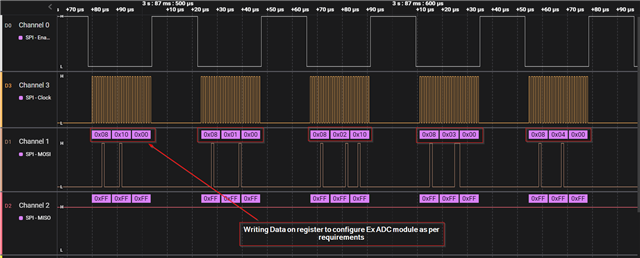
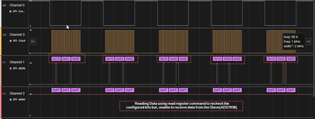
我已将 TMS320F280039C 控制卡与 ADS7038 IC 连接、根据数据表、我将发送配置数据并在数据写入是否正确的情况下读回、但我无法从 ADS7038模块接收任何数据。
配置如下:
>波特率:1MHz
>位大小: 8
>使用 FIFO
> SPI 模式0
>控制器模式
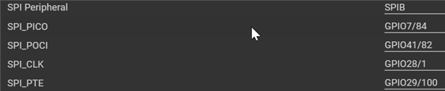
> PinMux:
我发送的代码如下所示:
void ADC_ExternalInit( void )
{
uint16_t i = 0;
static uint16_t tmp_Error_uint16_t = FALSE;
/* Write the configuration of the external ADC, instead of the last entry, that is activating the auto sequence mode. */
for ( i=0 ;i < ( ADC_Sys_Ex_StartupConfig_Length_u16 - 1u );i++ )
{
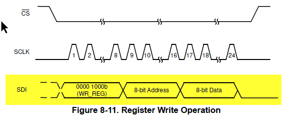
/* Write three times eight bit = 24-Bits in total. */
SPI_transmitNBytes(SPIB_BASE,(uint16_t *)&ADC_Sys_Ex_StartupConfig_a16[i*3], (uint16_t)3, (uint16_t)0);
/* Clear of fifo pointer is needed, otherwise the function SPI_writeDataBlocking will not work next time. */
SPI_clearFIFOPointer();
}
/* Readback the registers hat has been previously written to ensure the correct operation. */
for ( i=0;i<ADC_Sys_Ex_StartupConfigReadback_Length_u16;i++ )
{
/* Write three times eight bit = 24-Bits in total. */
SPI_transmitNBytes(SPIB_BASE,(uint16_t *)&ADC_Sys_Ex_StartupConfigReadback_a16[i*3], 3, 0);
if ( i >= 1u )
{
if ( SPI_M_READ_BUFFER != ADC_Sys_Ex_StartupConfig_a16[((i-1u)*3u)+2u] )
{
tmp_Error_uint16_t = TRUE;
}
}
SPI_clearFIFOPointer();
}
/* Check if an error is present during the external ADC setup. */
if ( tmp_Error_uint16_t == ( uint16_t ) TRUE )
{
ADC_Sys_Ex_ADCInit_uint16_t = FALSE;
}
else
{
ADC_Sys_Ex_ADCInit_uint16_t = TRUE;
/* Activate the auto sequence mode at the end of the init phase. */
SPI_transmitNBytes(SPIB_BASE,(uint16_t *)&ADC_Sys_Ex_StartupConfig_a16[(ADC_Sys_Ex_StartupConfig_Length_u16-1u)*3u], 3, 0);
/* Clear of fifo pointer is needed, otherwise the function SPI_writeDataBlocking will not work next time. */
SPI_clearFIFOPointer();
}
/***********************************************************************************/
extern void SPI_clearFIFOPointer ( void ) {
/* TX FIFO */
/* Write 0 to reset the FIFO pointer to zero, and hold in reset.*/
HWREGH(SPIB_BASE + SPI_FFTX_SPIRST) = SPI_D_FIFO_RESET;
/* RX FIFO */
/* Write 0 to reset the FIFO pointer to zero, and hold in reset.*/
HWREGH(SPIB_BASE + SPI_FFRX_RXFIFORESET) = SPI_D_FIFO_RESET;
/* Restart FIFO, first start with Rx - FIFO */
/* Release receive FIFO from reset. */
HWREGH(SPIB_BASE + SPI_FFRX_RXFIFORESET) = SPI_D_FIFO_RELEASE;
/* Release transmit FIFO from reset. */
HWREGH(SPIB_BASE + SPI_FFTX_SPIRST) = SPI_D_FIFO_RELEASE;
}
/***********************************************************************************/
static const uint16_t ADC_Sys_Ex_StartupConfig_a16 [] = {
ADC_EXT_WR_REG,0x10,0x00, /* Disable a current on going conversion. */
ADC_EXT_WR_REG,0x01,0x00, /* Reset the configuration at startupd. */
ADC_EXT_WR_REG,0x02,0x10, /* Append a 4-bit channel ID to the measured data. */
ADC_EXT_WR_REG,0x03,0x00, /* Oversampling is deactivated. */
ADC_EXT_WR_REG,0x04,0x00, /* 1 MHz sample rate + Auto sequence mode. */
ADC_EXT_WR_REG,0x05,0x00, /* All channels are configured as analog input. */
ADC_EXT_WR_REG,0x12,0x0F, /* CH0, CH1, CH2 and CH3 are enabled for the auto sequence mode. */
ADC_EXT_WR_REG,0x10,0x11, /* Start the auto sequence mode. */
};
static const uint16_t ADC_Sys_Ex_StartupConfigReadback_a16 [] = {
ADC_EXT_RD_REG,0x10,0x00, /* Disable a current on going conversion. */
ADC_EXT_RD_REG,0x01,0x00, /* Reset the configuration at startupd. */
ADC_EXT_RD_REG,0x02,0x00, /* Append a 4-bit channel ID to the measured data. */
ADC_EXT_RD_REG,0x03,0x00, /* Oversampling is deactivated. */
ADC_EXT_RD_REG,0x04,0x00, /* 1 MHz sample rate + Auto sequence mode. */
ADC_EXT_RD_REG,0x05,0x00, /* All channels are configured as analog input. */
ADC_EXT_RD_REG,0x12,0x00, /* CH0, CH1, CH2 and CH3 are enabled for the auto sequence mode. */
0x00,0x00,0x00 /* One additional row with dummy data to read out the last register. */
};
static uint16_t ADC_Sys_Ex_StartupConfig_Length_u16 = 8u;
static uint16_t ADC_Sys_Ex_StartupConfigReadback_Length_u16 = 8u;
/***********************************************************************************/
下面附加了输出代码段:
注:
> ADS7038在3.3电压下工作。
我有一些疑问:
1.外设模式下是否默认使用 ADS7038?
2.是否需要在 ADS7038中启用硬件写入/读取保护? 如果是、我该怎么做?
请告诉我问题可能在哪里、以及如何解决。
谢谢!
此致、
U·特哈斯
