This thread has been locked.

If you have a related question, please click the "Ask a related question" button in the top right corner. The newly created question will be automatically linked to this question.

[参考译文] ADS1299EEGFE-PDK:使用 ADS1299 将电极连接到皮肤时没有信号

Guru**** 2489685 points
Other Parts Discussed in Thread: ADS1299

请注意,本文内容源自机器翻译,可能存在语法或其它翻译错误,仅供参考。如需获取准确内容,请参阅链接中的英语原文或自行翻译。

https://e2e.ti.com/support/data-converters-group/data-converters/f/data-converters-forum/1539134/ads1299eegfe-pdk-there-is-no-signal-when-the-electrode-attached-to-skin-with-ads1299

部件号:ADS1299EEGFE-PDK
主题:ADS1299 中讨论的其他器件

工具/软件:

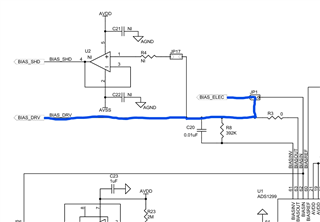
我正在研究 ADS1299 和 nRF52840 之间的 SPI 通信。 我有 ADS1299EEGFE-DK 板、但不使用 MMBO 板。 我成功建立了 ADS1299 与 nRF52840 之间的通信。 可以对寄存器进行读写。 当我尝试从 ADS1299 收集信号时、无法获得任何信号。 我使用的是专用偏置和基准电极。 我使用内部偏置进行驱动。 当我点击电极时、我可以看到输出的变化、但当我将电极连接到皮肤时、没有变化。 下面详细介绍了我使用的寄存器配置和硬件配置。 目前、我正在处理一个信道。
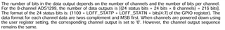
CONFIG1 -> 0xD6

CONFIG2 -> 0xC0

CONFIG3 -> 0xEC

CH1SET -> 0x60

MISC1 -> 0x20

JP2 -> 2-3 已连接

JP20 ->1-2 已连接

JP24 ->2-3 已连接

JP25 ->第 5 个引脚 BIAS_ELEC

JP25 ->第 6 引脚 REF_ELEC

JP25 -> 1-2 和 3-4 已连接

JP1 ->1-2 已连接

JP6 ->2-3 已连接

JP7 ->1-2 已连接

JP8 ->2-3 已连接

  • 请注意,本文内容源自机器翻译,可能存在语法或其它翻译错误,仅供参考。如需获取准确内容,请参阅链接中的英语原文或自行翻译。

    编辑版本:
    为了读取数据、我使用这个函数。 根据状态位、它必须返回 0xC000。 但当我尝试读取 STAT_1 变量时、会返回 0x00C0C0C0C0。  


    /** @brief Read Data Continuous Mode
        *
        *
        @details After RDATAC command received by ADS1299, it starts with RDATAC.
        Go over channel by channel and read values.
        @details This function returns channelData
    */
    void RDATAC_read_value(int32_t* channelData)
    {   
        new_data_available = false;
        uint32_t stat_1 = 0x00;
        static uint8_t dummy_message = 0x00; // __attribute__((aligned(4))) = 0x00;
        static uint8_t inByte;//        __attribute__((aligned(4)));
        //int32_t channelData[8];       // __attribute__((aligned(4))) = {0};
    
        nrf_gpio_pin_clear(CS_PIN);
    
        for(uint8_t i = 0; i < 3; i++)
        { 
          spi_transfer_byte(&dummy_message, &inByte, 1);
          stat_1 = (stat_1 << 8) | inByte;
        }
        
        for(uint8_t i = 0; i < 8; i++)
        { 
          for(uint8_t j = 0; j < 3; j++)
          {
            spi_transfer_byte(&dummy_message, &inByte, 1);
            channelData[i] = (channelData[i] << 8) | inByte;
          }
        }
        
        nrf_gpio_pin_set(CS_PIN);
        
        for (int i = 0; i < 8; i++) { // Convert 3-byte 2's complement to 4-byte 2's complement
            if ((channelData[i] >> 23) == 1) { // Check if bit 23 is 1 (negative number)
                channelData[i] |= 0xFF000000; // Sign-extend by setting upper 8 bits to 1
            } else {
                channelData[i] &= 0x00FFFFFF; // Clear upper 8 bits for positive number
            }
        }
    
        new_data_available = true;
    }
    

  • 请注意,本文内容源自机器翻译,可能存在语法或其它翻译错误,仅供参考。如需获取准确内容,请参阅链接中的英语原文或自行翻译。

    嗨、Omer、

    您能否尝试将通道配置为使用内部方波测试信号? 这将验证您的 ADS1299 是否正常运行以及数据传输是否正确。

    有关更多建议、另请参阅我们的 ADS129x 常见问题解答页面:

    【常见问题解答】TI ADS129x 系列生物电势 ADC 的常见问题 — 数据转换器论坛-数据转换器 — TI E2E 支持论坛 

    此致、

    Ryan