

请注意,本文内容源自机器翻译,可能存在语法或其它翻译错误,仅供参考。如需获取准确内容,请参阅链接中的英语原文或自行翻译。
部件号:ADS131M02 “线程: 测试”中讨论的其它部件
你好。
我使用 ADS131M02将照片二极管的值与 Raspberry PI 4B+进行转换。
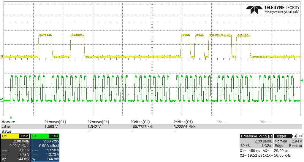
读取时钟寄存器时,响应数据为0x030E。 这是默认值。
并写入时钟寄存器,数据为0x030A,响应数据为0x4180。 这也是对的。
但再次读取时钟寄存器,响应数据为0x0264。
有什么问题?
if __name__ == "__main__":

    ad_rst.off()
    ad_rst.on()

    spi = spidev.SpiDev()

    spi.open(0, 0)
    spi.max_speed_hz = 50000
    #spi.max_speed_hz = 8192000
    #spi.max_speed_hz = 1000000
    spi.mode = 0b01

    tmp = [0xA1,0x80]
    crcr = calCRC16(tmp,0,2)
    crcr1 = (crcr&0xFF00)>>8
    crcr2 = crcr&0x00FF
    tmp.extend([crcr1,crcr2])
    spi.xfer(tmp)
    rrr = spi.readbytes(24)
    print(rrr)

    tmp = [0x61,0x80,0x03,0x0A]
    crcr = calCRC16(tmp,0,4)
    crcr1 = (crcr&0xFF00)>>8
    crcr2 = crcr&0x00FF
    tmp.extend([crcr1,crcr2])
    spi.xfer(tmp)
    rrr = spi.readbytes(24)
    print(rrr)

    tmp = [0xA1,0x80]
    crcr = calCRC16(tmp,0,2)
    crcr1 = (crcr&0xFF00)>>8
    crcr2 = crcr&0x00FF
    tmp.extend([crcr1,crcr2])
    spi.xfer(tmp)
    rrr = spi.readbytes(24)
    print(rrr)


