您好!
我尝试使用 DAC8571使用 Arduino 并使用 https://github.com/baku1413/DAC8571库 、但无法使其正常工作。
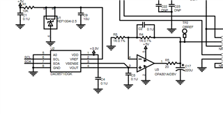
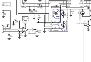
下面是我的 DAC 电路

This thread has been locked.
If you have a related question, please click the "Ask a related question" button in the top right corner. The newly created question will be automatically linked to this question.
您好!
我尝试使用 DAC8571使用 Arduino 并使用 https://github.com/baku1413/DAC8571库 、但无法使其正常工作。
下面是我的 DAC 电路

DAC 我能够编码直至输出为5V,但有时显示为5V,有时显示为0.6V。
我每次进行编码时都无法将其编码为固定值?
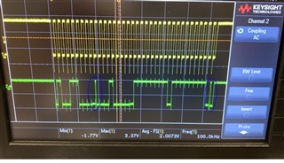
绿色 SDA
黄色 SCL。
我的 Arduino 代码:
Wire.begin();
Wire.beginTransmission(0b01001100);//地址
Wire.write (0b00010000); //设置立即更新
Wire.write (0xff);// max
Wire.write (0xff);// max
wire.endTransmission ();
}


您好、Samarth、
示波器屏幕截图中的 I2C 序列看起来正确、看起来 DAC 正在确认其应位于何处。 您的基准电压为2.5V。 您是否能够探测 DAC 输出、并让我们知道写入0xFFFF 时 DAC 输出是否为2.5V? 编写中间代码(0x8000)时、DAC 输出端是否看到1.25V 电压? 让我们首先尝试验证 DAC 是否正常工作。
最棒的
Katlynne Jones
您好!
Wire.begin();
Wire.beginTransmission(0b01001100);
Wire.write (0b00010000);//发送五个字节
Wire.write (0x00);
Wire.write (0x00);//发送一个字节
wire.endTransmission ();
上述代码运行一次、输出如下
对于 FFFF 输出、
引脚1 = 3.3V
PIN2=2.5V
引脚3=2.5V
PIN4=2.5
pin5=.1V
PIN6=3.3V
PIN7=3.3V
PIN8=.1V
但到达引脚3和4至2.5V 大约需要4分钟。这是非常奇怪的。我继续测量4分钟、在某个时刻、它从0.1升至2.5V
输出为0
引脚1 = 3.3V
PIN2=2.5V
引脚3=.1V
PIN4=.1
pin5=.1V
PIN6=3.3V
PIN7=3.3V
PIN8=.1V