This thread has been locked.
If you have a related question, please click the "Ask a related question" button in the top right corner. The newly created question will be automatically linked to this question.
https://e2e.ti.com/support/data-converters-group/data-converters/f/data-converters-forum/868742/ads7951-q1-ads7951-q1inaccurate-acquisition-accuracy
当收集0V 电压时、该仪器的输出数据为0x0032
尊敬的用户6251042:
欢迎来到我们的论坛。
向 ADC 应用精确的0V 输入信号时、很少读取精确为0x0000的转换代码。 这是由于任何 ADC 的固有偏移。 但是、您读取的代码远大于 ADS7951-Q1数据表中指定的偏移误差。 这意味着存在关闭的情况。
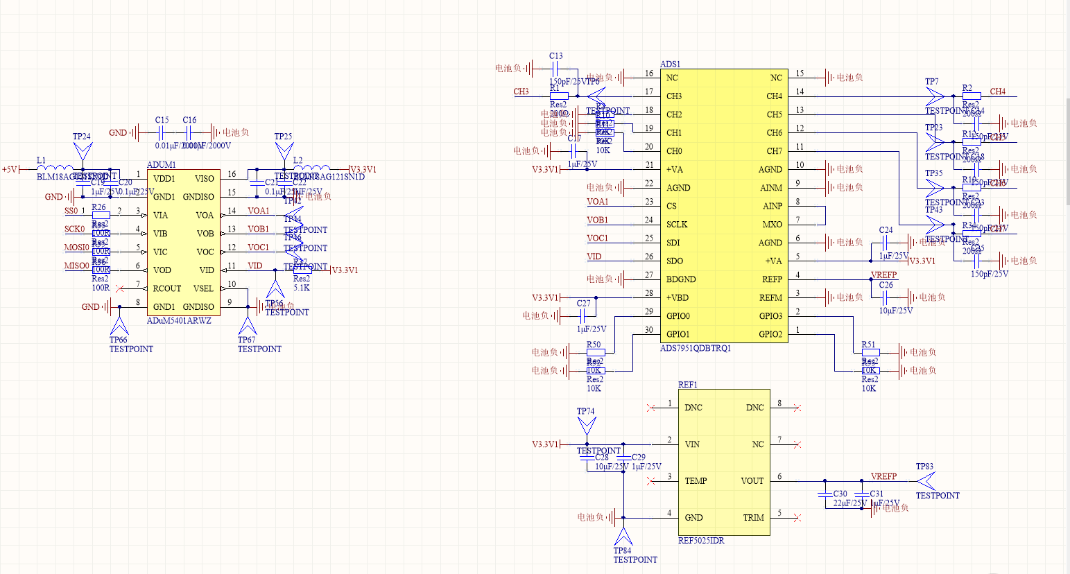
您能否分享有关 ADC 设置的更多详细信息以及可能的原理图、以了解我们是否能够识别出其中的任何问题?
此致、
大家好、感谢您的回复!
我的 MCU 已重新扫描 MC9S12G128、 通信模式为 SPI.CPOL=0、CPHA=0;
空 ADS1 (空) { ADS1_CS = 0; SPI0_SEND (0x1980); TEMP1 = SPI0_Receive (); temp11=temp1>>12; TEMP1 = temp1<<4; TEMP1 = temp1>>4; delay1us(20); ADS1_CS = 1; delay1us(20); ADS1_CS = 0; SPI0_SEND (0x1200); TEMP2 = SPI0_Receive (); temp12=temp2>>12; TEMP2 = temp2<<4; TEMP2 = temp2>>4;//采集电池总电压,单位mV delay1us(20); ADS1_CS = 1; delay1us(20); ADS1_CS = 0; SPI0_SEND (0x1280); temp3 = SPI0_receive (); temp13=temp3>>12; temp3 = temp3<<4; temp3 = temp3>>4; ADS1_CH3 =(unsigned long int)((unsigned long int)(temp3)*2500/4095)*255); delay1us(20); ADS1_CS = 1; delay1us(20); ADS1_CS = 0; SPI0_SEND (0x1300); temp4 = SPI0_receive (); temp14=temp4>>12; temp4 = temp4<<4; temp4 = temp4>>4; ADS1_CH4 =(unsigned long int)((unsigned long int)(temp4)*2500/4095)*255); delay1us(20); ADS1_CS = 1; delay1us (20);}
非常感谢您提供这些详细信息。 我的一位同事、他是该 ADC 的专家、将会与您联系。
您好,您能给我解决这个问题的办法吗?谢谢
您好!
对因节假日而延迟答复表示歉意。
如果我理解正确、您将输入接地、但读数高于测量值、这是正确的吗?
从您共享的原理图中可以看到、这似乎很好。 您如何提供0V 输入? 您实际上是将输入接地还是输入源提供0V 电压?
输入源是什么? ADC 的采样率是多少? 您是否会测量 ADC 引脚上的输入并与 ADC 转换结果进行比较?
感谢您提供该代码、但您是否会提供一个示波器来显示微控制器和 ADC 之间的数字通信? 这将有助于确认时序、并确保我们希望代码颁布的内容实际上是器件通过视觉比较看到的内容。
请务必包含3帧、因为此器件具有2帧延迟。
根据您提供的代码、看起来您正在尝试使用 手动模式测量通道3、4、5和6。
此致
Cynthia