

Other Parts Discussed in Thread: TCA9546A
请注意,本文内容源自机器翻译,可能存在语法或其它翻译错误,仅供参考。如需获取准确内容,请参阅链接中的英语原文或自行翻译。
器件型号:TCA9546A 您好!
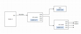
在我们的应用中、我们有一个地址为0x77的 TCA9546A 连接到运行 Ubuntu 的 Cortex A 的内核 i2c2。 我们能够探测连接到开关0x77通道0的器件。 在通道1上、我们有另一个具有 addr 0x70的 i2c 开关。 我们在使用 addr 0x70探测交换机时遇到问题。 我想知道您是否有与多层 i2c 开关的器件树实现相关的文档或支持、如我们的案例所示。
谢谢、
Nikhil
