This thread has been locked.

If you have a related question, please click the "Ask a related question" button in the top right corner. The newly created question will be automatically linked to this question.

[参考译文] TCA9534:无法使用 I2C4从微控制器 TM4C1294ncpdt 驱动 IO 扩展器 TCA9534PWR

Guru**** 2386620 points
Other Parts Discussed in Thread: TM4C1294NCPDT, TCA9534
请注意,本文内容源自机器翻译,可能存在语法或其它翻译错误,仅供参考。如需获取准确内容,请参阅链接中的英语原文或自行翻译。

https://e2e.ti.com/support/interface-group/interface/f/interface-forum/1290370/tca9534-unable-to-drive-the-io-expander-tca9534pwr-from-microcontroller-tm4c1294ncpdt-using-i2c4

器件型号:TCA9534
主题中讨论的其他器件:TM4C1294NCPDT

无法使用 I2C4从微控制器 TM4C1294ncpdt 驱动 IO 扩展器 TCA9534PWR。 我已初始化 I2C4、并尝试将 IO 扩展器 TCA9534配置为输出。 但以某种方式成功配置了芯片。 以下是 I2C 配置的快照(地址0x27、CONFIG 寄存器0x03并为所有输出写入数据值0x00)。

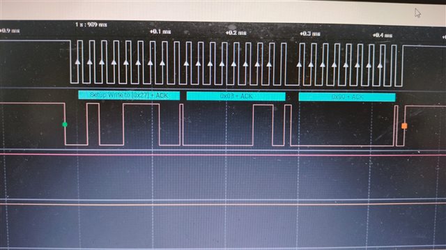
随后是我在当前项目中用于驱动 IO 扩展器的源代码。 void I2C_init(){//############ 初始化############################ //在使用之前必须启用 I2C3外设。 SysCtlPeripheralEnable (SYSCTL_Periph_I2C3);SysCtlPeripheralReset (SYSCTL_Periph_I2C3);// I2C4外设在使用前必须被启用。 SysCtlPeripheralEnable (SYSCTL_Periph_I2C4);SysCtlPeripheralReset (SYSCTL_Periph_I2C4);SysCtlPeripheralEnable (SYSCTL_Periph_GPIOK);GPIOPinConfigure (GPIO_PK4_I2C3SCL);GPIOPinConfigure (GPIO_PK5_I2SDA); GPIOPinTypeI2CSCL (GPIO_PORTK_BASE、GPIO_PIN_4);GPIOPinTypeI2C (GPIO_PORTK_BASE、GPIO_PIN_5);I2CMasterInitExpClk (I2C3_base、 G_ui32SysClock、false);// I2CMasterSlaveAddrSet (I2C3_base、slave_address、false); //从地址到0x20 I2CMasterEnable (I2C3_BASE);GPIOPinConfigure (GPIO_PK6_I2C4SCL);GPIOPinConfigure (GPIO_PK7_I2C4SDA);GPIOPinTypeI2CSCL (GPIO_PORTK_BASE、GPIO_PIN_6); GPIOPinTypeI2C (GPIO_PORTK_BASE、GPIO_PIN_7);I2CMasterInitExpClk (I2C4_BASE、g_ui32SysClock、false); I2CMasterSlaveAddrSet (I2C4_base、0x27、false);//从器件地址更改为0x27 I2CMasterEnable (I2C4_base);I2CMasterGlitchFilterConfigSet (I2C3_base、I2C_MASTER_glitch_FILTER_2);I2CMasterGlitchConfigSet (I2C4_base、I2C_MASTER_FILTER_2);I2CMaster_FILTER_FILTER_2) void I2CSend4 (uint8_t slave_addr、uint8_t num_of_args、...) {uint8_t i =0;//告诉主模块在与从模块进行通信时将在总线上放置的地址// I2CMasterSlaveAddrSet (I2C4_BASE、slave_addr、false);//存储可变数量参数 va_list vargs 的列表;//指定 va_list 为"open",最后一个固定参数//so vargs 知道从何处开始查找 va_start (vargs、num_of_args);//将数据放入 FIFO (iint2c4)中(iint_vargs、uart_data_vargs); //如果只有一个参数,我们只需要使用//单个 send I2C 函数 if (num_of_args == 1){//发起从 MCU I2CMasterControl (I2C4_base、I2C_MASTER_CMD_SINGLE_SEND)发送数据;//等待 MCU 完成传输。 while (I2CMasterBusy (I2C4_base);//"关闭"变量参数列表 va_end (vargs);}//否则,我们在//I2C 总线上开始传输多个字节 else{//启动从 MCU I2CMasterControl (I2C4_base、I2C_MASTER_CMD_BURST_SEND_START)发送数据;//直到 MCU 完成传输。 while (I2CMasterBusy (I2C4_base));//发送 num_of_args-2段数据、使用 I2C 模块的//burst_send_cont 命令执行以下操作(i = 1;i <(num_of_args - 1);i++){//将下一段数据放入 I2C FIFO I2sture_send_cont (iCM2ster_dataPut)、i2c4 (iCM_base_arg_1)、I2c4 (i2c4)、直接发送到 I2c4 (iCM_base_c4); //等待 MCU 完成传输。 while (I2CMasterBusy (I2C4_base);}//将最后一段数据放入 I2C FIFO I2CMasterDataPutt (I2C4_base、va_arg (vargs、uint32_t));//发送刚刚放入 FIFO 的下一个数据 I2CMasterControl (I2C4_BASE、I2C_MASTER_CMD_WAITE_MCU);//发送完成之前)。 while (I2CMasterBusy (I2C4_BASE);//"close "变量 args list va_end (vargs);}//在从器件上读取指定的寄存器 uint32_t I2CReceive4 (uint32_t slave_addr、uint8_t reg){//指定我们正在将(寄存器地址)写入从器(eint32_t I2C4寄存器地址)、eSlaveAddr、///指定为从器、eSlaveAddr、e2I 地址);//指定从器; //将控制字节和寄存器地址字节发送到从器件 I2CMasterControl (I2C4_BASE、I2C_MASTER_CMD_BURST_SEND_START);//等待 MCU 完成事务 while (I2CMasterBusy (I2C4_BASE));//指定我们将从从从器件 I2CMSlavastereAddrSet (I2CMasterBusy (I2C4_BASE/STED/BEEDBACK)读取;//指定的控制/从 I2CMaster_BYTE、I2CD_BET_BIST_BEEDBY_FEEDBACK、I2CM_FAC_CONTROL_CASE); //等待 MCU 完成事务 while (I2CMasterBusy (I2C4_base));//返回从指定寄存器拉取的数据返回 I2CMasterDataGet (I2C4_base);}void set_output (){I2CSend4 (SLAVE_DR1、2、0x03、0x00);void Write_output (uint8_t pin、1、2、}0x01;}

  • 请注意,本文内容源自机器翻译,可能存在语法或其它翻译错误,仅供参考。如需获取准确内容,请参阅链接中的英语原文或自行翻译。

    void I2c_init()
    {
        //#######INITIALIZATION############
    
                // The I2C3 peripheral must be enabled before use.
                SysCtlPeripheralEnable(SYSCTL_PERIPH_I2C3);
                SysCtlPeripheralReset(SYSCTL_PERIPH_I2C3);
    
                // The I2C4 peripheral must be enabled before use.
                SysCtlPeripheralEnable(SYSCTL_PERIPH_I2C4);
                SysCtlPeripheralReset(SYSCTL_PERIPH_I2C4);
    
                SysCtlPeripheralEnable(SYSCTL_PERIPH_GPIOK);
    
                GPIOPinConfigure(GPIO_PK4_I2C3SCL);
                GPIOPinConfigure(GPIO_PK5_I2C3SDA);
    
                GPIOPinTypeI2CSCL(GPIO_PORTK_BASE, GPIO_PIN_4);
                GPIOPinTypeI2C(GPIO_PORTK_BASE, GPIO_PIN_5);
                I2CMasterInitExpClk(I2C3_BASE, g_ui32SysClock, false);
               // I2CMasterSlaveAddrSet(I2C3_BASE, SLAVE_ADDRESS , false); // slave address to 0x20
                I2CMasterEnable(I2C3_BASE);


                GPIOPinConfigure(GPIO_PK6_I2C4SCL);
                GPIOPinConfigure(GPIO_PK7_I2C4SDA);
    
                GPIOPinTypeI2CSCL(GPIO_PORTK_BASE, GPIO_PIN_6);
                GPIOPinTypeI2C(GPIO_PORTK_BASE, GPIO_PIN_7);
                I2CMasterInitExpClk(I2C4_BASE, g_ui32SysClock, false);
                I2CMasterSlaveAddrSet(I2C4_BASE, 0x27 , false); // slave address to 0x27
                I2CMasterEnable(I2C4_BASE);
    
                I2CMasterGlitchFilterConfigSet(I2C3_BASE, I2C_MASTER_GLITCH_FILTER_2);
                I2CMasterGlitchFilterConfigSet(I2C4_BASE, I2C_MASTER_GLITCH_FILTER_2);
    
          }
    
    void I2CSend4(uint8_t slave_addr, uint8_t num_of_args, ...)
    {
        uint8_t i =0;
        // Tell the master module what address it will place on the bus when
        // communicating with the slave.
        I2CMasterSlaveAddrSet(I2C4_BASE, slave_addr, false);
    
        //stores list of variable number of arguments
        va_list vargs;
    
        //specifies the va_list to "open" and the last fixed argument
        //so vargs knows where to start looking
        va_start(vargs, num_of_args);
    
        //put data to be sent into FIFO
        I2CMasterDataPut(I2C4_BASE, va_arg(vargs, uint32_t));
    
        //if there is only one argument, we only need to use the
        //single send I2C function
        if(num_of_args == 1)
        {
            //Initiate send of data from the MCU
            I2CMasterControl(I2C4_BASE, I2C_MASTER_CMD_SINGLE_SEND);
    
            // Wait until MCU is done transferring.
            while(I2CMasterBusy(I2C4_BASE));
    
            //"close" variable argument list
            va_end(vargs);
        }
    
        //otherwise, we start transmission of multiple bytes on the
        //I2C bus
        else
        {
            //Initiate send of data from the MCU
            I2CMasterControl(I2C4_BASE, I2C_MASTER_CMD_BURST_SEND_START);
    
            // Wait until MCU is done transferring.
            while(I2CMasterBusy(I2C4_BASE));
    
            //send num_of_args-2 pieces of data, using the
            //BURST_SEND_CONT command of the I2C module
            for( i = 1; i < (num_of_args - 1); i++)
            {
                //put next piece of data into I2C FIFO
                I2CMasterDataPut(I2C4_BASE, va_arg(vargs, uint32_t));
                //send next data that was just placed into FIFO
                I2CMasterControl(I2C4_BASE, I2C_MASTER_CMD_BURST_SEND_CONT);
    
                // Wait until MCU is done transferring.
                while(I2CMasterBusy(I2C4_BASE));
            }
    
            //put last piece of data into I2C FIFO
            I2CMasterDataPut(I2C4_BASE, va_arg(vargs, uint32_t));
            //send next data that was just placed into FIFO
            I2CMasterControl(I2C4_BASE, I2C_MASTER_CMD_BURST_SEND_FINISH);
            // Wait until MCU is done transferring.
            while(I2CMasterBusy(I2C4_BASE));
    
            //"close" variable args list
            va_end(vargs);
        }
    }
    //read specified register on slave device
    uint32_t I2CReceive4(uint32_t slave_addr, uint8_t reg)
    {
        //specify that we are writing (a register address) to the
        //slave device
        I2CMasterSlaveAddrSet(I2C4_BASE, slave_addr, false);
    
        //specify register to be read
        I2CMasterDataPut(I2C4_BASE, reg);
    
        //send control byte and register address byte to slave device
        I2CMasterControl(I2C4_BASE, I2C_MASTER_CMD_BURST_SEND_START);
    
        //wait for MCU to finish transaction
        while(I2CMasterBusy(I2C4_BASE));
    
        //specify that we are going to read from slave device
        I2CMasterSlaveAddrSet(I2C4_BASE, slave_addr, true);
    
        //send control byte and read from the register we
        //specified
        I2CMasterControl(I2C4_BASE, I2C_MASTER_CMD_SINGLE_RECEIVE);
    
        //wait for MCU to finish transaction
        while(I2CMasterBusy(I2C4_BASE));
    
        //return data pulled from the specified register
        return I2CMasterDataGet(I2C4_BASE);
    }
    
    void Set_output()
    {
       I2CSend4(SLAVE_DR1, 2, 0x03, 0x00); 
    }
    
    void Write_output(uint8_t pin)
    {
       I2CSend4(SLAVE_DR1,2, 0x01, pin);
    }

  • 请注意,本文内容源自机器翻译,可能存在语法或其它翻译错误,仅供参考。如需获取准确内容,请参阅链接中的英语原文或自行翻译。

    这些 I²C Ω 波形看起来不错。

    您遇到的问题是什么?

  • 请注意,本文内容源自机器翻译,可能存在语法或其它翻译错误,仅供参考。如需获取准确内容,请参阅链接中的英语原文或自行翻译。

    您好、Ramesh、

    您写入配置寄存器以将所有 p 端口设置为输出、但您是否也写入输出端口寄存器以在高逻辑电平和低逻辑电平之间切换?  

    此致、

    泰勒

  • 请注意,本文内容源自机器翻译,可能存在语法或其它翻译错误,仅供参考。如需获取准确内容,请参阅链接中的英语原文或自行翻译。

    我们已经解决了这个问题。 正确的寄存器分配2. 我们修整了整个代码以减小存储器大小。