Hai 团队、
我们将 MSDI 与微控制器连接。 开关与 MCU 之间的 SPI 通信正在正常运行。 我们将通道0、2、4、6连接为接地。 我们也能够读取 MSDI 器件 ID 寄存器。
它返回为0x20 。
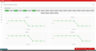
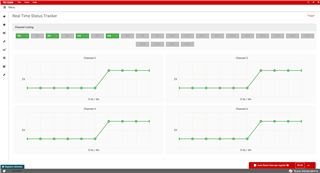
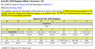
但我们无法通过在按下开关的同时读取状态寄存器(0x05)来检测开关变化。 但它会在硬件中发生变化。
我们编写了附加的配置。 一旦配置完成、信号电压 增加至4.5V (为什么增加)。 实际上是2.4V、未按下开关。
请找到以下配置。 您能帮我解决任何配置问题吗? 配置之前的电压为:输出按下开关时为2.4V、按下开关时为1.3V。 我们将2V 编程为比较器阈值。
Step1:Enable input channels 0 2 4 6 (Requirement)
Register 1BH

23 22 21 20 19 18 17 16 15 14 13 12 11 10 9 8 7 6 5 4 3 2 1 0
 0  0  0  0  0  0  0  0  0  0  0  0  0  0 0 0 0 1 0 1 0 1 0 1 ---->0x000055


Setp2: Current Source Selection:

Register 1CH

Configure all to source selection [0h]


23 22 21 20 19 18 17 16 15 14 13 12 11 10 9 8 7 6 5 4 3 2 1 0  ----> 0x000000
 0  0  0  0 0  0   0  0  0  0  0  0  0  0 0 0 0 0 0 0 0 0 0 0


Step3: Wetting Current Configuration

WC_CFG0 Register 1Dh : wetting current Configure to 2mA[2h]


23 22 21 20 19 18 17 16 15 14 13 12 11 10 9 8 7 6 5 4 3 2 1 0 ---> 0x002092
0  0  0  0  0  0  0  0   0  0  1  0  0  0 0 0 1 0 0 1 0 0 1 0


WC_CFG1 Register 1EH : Wetting current configure to 2mA[2H]


23 22 21 20 19 18 17 16 15 14 13 12 11 10 9 8 7 6 5 4 3 2 1 0 ---> 0X000000
0  0  0  0  0   0  0  0 0  0  1  0  0  0  0 0 1 0 0 1 0 0 1 0


Step4: Mode Selection

Mode Register 32h


23 22 21 20 19 18 17 16 15 14 13 12 11 10 9 8 7 6 5 4 3 2 1 0 ---> 0x000000
0  0  0  0   0  0  0  0  0  0  0  0  0  0 0 0 0 0 0 0 0 0 0 0


Step 5: Set Device Configuration

Register Address 1AH
Set trigger to 0 [Stop Device]
VS Ratio to 1 - to support voltage range from 4.5 to 30v
polling enabled
INT_CONFIG - Interrupt Assertion to static
crc disabled
Polling activation time 1024us[bh]
polling time 4ms [1h]


23 22 21 20 19 18 17 16 15 14 13 12 11 10 9 8 7 6 5 4 3 2 1 0 ---> 0x953562
1  0  0  1  0  1  0  1  0  0  1  1  0  1  0 1 0 1 1 0 0 0 1 0


Step 6 : Comparator Thresholds Configuration

THRES_COMP Register 21h:
Set to 3h - threshold voltage to 2V

Digital Inputs 00 02 04 06

23 22 21 20 19 18 17 16 15 14 13 12 11 10 9 8 7 6 5 4 3 2 1 0 ---> 0x000000
0  0  0  0   0  0  0  0  0  0  0  0  0  0 0 0 0 0 0 0 0 0 0 0


Step 7 :Enable global interrupt on state change

INT_EN_CFG0 Register 24h: Global Interput
SSC_EN TO enable interrupt assertion on Switch State Change


23 22 21 20 19 18 17 16 15 14 13 12 11 10 9 8 7 6 5 4 3 2 1 0 ---> 0x000004
0  0  0  0  0  0  0  0  0  0  0  0   0  0 0 0 0 0 0 0 0 1 0 0


Step 8: Interrupts detection configuration
Register is 0x22

Digital Input 00,02,04,06

23 22 21 20 19 18 17 16 15 14 13 12 11 10 9 8 7 6 5 4 3 2 1 0 ---> 0x003333
0  0  0  0  0  0  0  0  0  0  1   1  0 0  1 1 0 0 1 1 0 0 1 1


Step 9 : Enable Device to Start Operation:

Now all the required settings done, enable trigger for normal operation

CONFIG Register 1Ah:

23 22 21 20 19 18 17 16 15 14 13 12 11 10 9 8 7 6 5 4 3 2 1 0 ---> 0x812D62(Requirement)


Step 9 : Monitor status
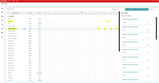
IN_STAT_COMP

IN_STAT_COMP Register 05h:

Read the contetns of STAT_COMP Register to verify the changes but it is not changing with pressing the switch.


