

https://e2e.ti.com/support/logic-group/logic/f/logic-forum/1484892/tpld1201-tpld1201dgsr
器件型号:TPLD1201工具与软件:
我将尝试复制第一个示例、其中只有两个模拟比较器、但第一个示例似乎能按预期工作。
如果我使用原始示例、它将实现完美的运行。 如果我从空状态开始、它不起作用。
以下是从演示中保存的文件内容、可以正常工作、然后是异常内容:
/**
*这些参数是在生成该文件时使用的。 它们将自动应用于后续负载
*通过 GUI 或 CLI 运行 CLI 并使用'--help'获取有关如何覆盖这些参数的更多信息。
*@cliArgs --设备"TPLD1201_DGS_TL"-部件"默认"-包装"DGS (VSSOP, 10 )"-产品"TPLD@1.3.1+869"
*@v2CliArgs --设备"TPLD1201"-封装"DGS (VSSOP, 10 )"-产品"TPLD@1.3.1+869"
*@版本{"tool":"1.22.0+3893"}
*/
/**
*导入此配置中使用的模块。
*/
const acmp = scripting.AddModule ("scripting.AddModule"/ti/tpld/ACMP、{}、false);
const ACMP1 = ACMP.addInstance();
const ACMP2 = ACMP.addInstance();
const PIN = scripting.AddModule ("Scripting"/ti/tpld/PIN、{}、false);
const PIN1 = PIN.addInstance();
const PIN2 = PIN.addInstance();
const PIN3 = PIN.addInstance();
const PIN4 = PIN.addInstance();
const PIN5 = PIN.addInstance();
const Simulation = scripting.AddModule ("/ti/tpld/Simulation);
const VCC = scripting.AddModule ("/ti/tpld VCC "、{}、false);
const VCC1 = VCC.addInstance() VCC;
/**
*将自定义配置值写入导入的模块。
*/
acmp1.$name ="acmp0";
ACMP1.Vref_sel = 26;
ACMP1.HW.$ASSIGN ="ACMP0";
acmp2.$name ="acmp1";
ACMP2.Vref_sel = 26;
ACMP2.inp_sel = 2;
pin1.$name ="IO6";
pin1.type ="DOUT";
pin1.$topLabel ="如果电压\nr1 > r2\ntop 电位器>中间电位器\n";
pin1.hw.$assign ="IO6";
PIN2.$name ="IO7";
PIN2.TYPE ="DOUT";
PIN2.$topLabel ="LED 7\n 如果电压\nR4 > R2\n 底部电位器>中间电位器\n";
PIN2.HW.$ASSIGN ="IO7";
ACMP1.inp =引脚3;
pin3.$name ="ACMP0_IN";
pin3.sim ="正弦";
pin3.$topLabel ="R1";
pin3.hw.$assign ="IO1";
pin3.sine.$name ="ti_tpld_simulationOptions_SINE0";
pin3.sine.amplitude ={val:1.65、单位:"V"};
ACMP1.inm =引脚4;
ACMP2.inm =引脚4;
PIN4.$name ="ACMPx_IN";
PIN4.sim ="正弦";
PIN4.$topLabel ="R2";
PIN4.HW.$ASSIGN ="IO2";
PIN4.sine.$name ="ti_tpld_simulationOptions_SINE1";
pin4.sine.amplitude ={val:1.65、单位:"V"};
PIN4.sine.phase = 90;
ACMP2.inp =引脚5;
PIN5.$name ="ACMP1_IN";
PIN5.sim ="正弦";
PIN5.$topLabel ="R4";
PIN5.HW.$ASSIGN ="IO4";
PIN5.SINE.$NAME ="ti_tpld_simulationOptions_SINE2";
pin5.sine.amplitude ={val:1.65、单位:"V"};
PIN5.SINE.PHASE = 180;
const system = scripting.AddModule ("scripting.AddModule"/ti/tpld/SYSTEM、{}、false);
simulation.tstep ={val:1、单位:"us"};
VCC1.$name ="VCC0";
/**
*模块之间的连接
*/
scripting.connect (ACMP1、"out"、PIN1、"in");
scripting.connect (ACMP2、"out"、PIN2、"in");
scripting.connect (VCC1、"out"、ACMP1、"PUP");
scripting.connect (VCC1、"out"、ACMP2、"PUP");
/**
在图形中显示的模块的*(x,y)坐标
*/
ACMP1.$POSITION =[325,155];
ACMP2.$POSITION =[325,255];
pin1.$position =[555,170];
PIN2.$POSITION =[730,270];
pin3.$position =[140,140];
PIN4.$POSITION =[140,220];
PIN5.$POSITION =[140,300];
VCC1.$Position =[270,120];
/**
*用于解锁引脚/外设的 Pinmux 解决方案。 这可确保将来对自动解算器进行细微更改
*该工具的版本不会影响您最初看到的 pinmux。 可以按照完全删除这些行
*从头开始重新解决。
*/
ACMP2.HW.$inductionestSolution ="ACMP1";
system.hw.$indicestSolution ="系统";
/**
*这些参数是在生成该文件时使用的。 它们将自动应用于后续负载
*通过 GUI 或 CLI 运行 CLI 并使用'--help'获取有关如何覆盖这些参数的更多信息。
*@cliArgs --设备"TPLD1201_DGS_TL"-部件"默认"-包装"DGS (VSSOP, 10 )"-产品"TPLD@1.3.1+869"
*@v2CliArgs --设备"TPLD1201"-封装"DGS (VSSOP, 10 )"-产品"TPLD@1.3.1+869"
*@版本{"tool":"1.22.0+3893"}
*/
/**
*导入此配置中使用的模块。
*/
const acmp = scripting.AddModule ("scripting.AddModule"/ti/tpld/ACMP、{}、false);
const ACMP1 = ACMP.addInstance();
const ACMP2 = ACMP.addInstance();
const PIN = scripting.AddModule ("Scripting"/ti/tpld/PIN、{}、false);
const PIN1 = PIN.addInstance();
const PIN2 = PIN.addInstance();
const VCC = scripting.AddModule ("/ti/tpld VCC "、{}、false);
const VCC1 = VCC.addInstance() VCC;
/**
*将自定义配置值写入导入的模块。
*/
acmp1.$name ="acmp0";
ACMP1.Vref_sel = 26;
ACMP1.HW.$ASSIGN ="ACMP0";
acmp2.$name ="acmp1";
ACMP2.Vref_sel = 26;
ACMP2.inp_sel = 2;
pin1.$name ="PIN2";
pin1.type ="DOUT";
pin1.hw.$assign ="IO6";
PIN2.$name ="pin4";
PIN2.TYPE ="DOUT";
PIN2.HW.$ASSIGN ="IO7";
const PIN3 = PIN.addInstance ({}、false);
pin3.$name ="pin1";
ACMP1.inm =引脚3;
ACMP2.inm =引脚3;
pin3.hw.$assign ="IO2";
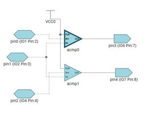
const PIN4 = PIN.addInstance ({}、false);
PIN4.$name ="pin3";
ACMP1.inp =引脚4;
PIN4.HW.$ASSIGN ="IO1";
const PIN5 = PIN.addInstance ({}、false);
PIN5.$name ="pin0";
ACMP2.inp =引脚5;
PIN5.HW.$ASSIGN ="IO4";
const system = scripting.AddModule ("scripting.AddModule"/ti/tpld/SYSTEM、{}、false);
VCC1.$name ="VCC0";
/**
*模块之间的连接
*/
scripting.connect (ACMP1、"out"、PIN2、"in");
scripting.connect (ACMP2、"out"、PIN1、"in");
scripting.connect (VCC1、"out"、ACMP1、"PUP");
scripting.connect (VCC1、"out"、ACMP2、"PUP");
/**
在图形中显示的模块的*(x,y)坐标
*/
ACMP1.$Position =[0、0];
ACMP2.$Position =[0165];
pin1.$position =[150,180];
PIN2.$POSITION =[150、15];
pin3.$position =[-195、90];
PIN4.$POSITION =[-195、15];
PIN5.$POSITION =[-200,180];
VCC1.$position =[-60、-65];
/**
*用于解锁引脚/外设的 Pinmux 解决方案。 这可确保将来对自动解算器进行细微更改
*该工具的版本不会影响您最初看到的 pinmux。 可以按照完全删除这些行
*从头开始重新解决。
*/
ACMP2.HW.$inductionestSolution ="ACMP1";
system.hw.$indicestSolution ="系统";
有什么建议吗?
提前感谢您
Luca Pizzini
