If you have a related question, please click the "Ask a related question" button in the top right corner. The newly created question will be automatically linked to this question.
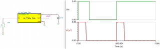
* Pulse generator using RC delay element
.SUBCKT PULSE_GEN IN OUT VCC VEE
* Pulse width value is in nanoseconds
+ PARAMS:
+ PULSENS 100

* Input is buffered to avoid loading issues
* Threshold is set to VCC/2
EINBUF INBUF VEE VALUE = {IF(V(IN,VEE)>V(VCC,VEE)/2,1,0)}

* Threshold value for timer circuit (1 time constant)
VTHR VTH VEE     0.632119

* R*C provides delay for pulse generator
R1  INBUF TIMER {PULSENS}
C1  TIMER VEE   1E-9

* Delayed output from the timer
EDELAY DELAY VEE VALUE = {IF(V(TIMER,VEE)>V(VTH,VEE),1,0)}

* To get the delay, I multiply the input state (0 or 1) by the
* inverted delayed signal state (0 or 1) to get a short pulse
ELOGIC  LOGIC VEE VALUE = {V(INBUF,VEE) * (1-V(DELAY,VEE))}

* I then use the VCC/VEE connections to determine the output voltage for the pulse:
EOUT OUT VEE VALUE = {V(VCC,VEE) * V(LOGIC,VEE)}
.ENDS
*$