Other Parts Discussed in Thread: EVM430-FR6047, MSP430FR6047
请注意,本文内容源自机器翻译,可能存在语法或其它翻译错误,仅供参考。如需获取准确内容,请参阅链接中的英语原文或自行翻译。
器件型号:MSP430FR6047主题中讨论的其他器件:EVM430-FR6047、
工具/软件:
您好!
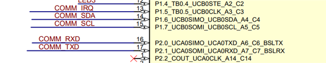
我仅使用 MSP430FR6047 及其配套器件、基于 EVM430-FR6047 设计了自己的水跟踪板。
因此、我无法使用 USS 设计中心、因为我要通过 TTL 串行接口连接到 USB 设备的串行端口、并且没有能够连接的 UID。 如果您知道一种无需 USB/HIDbridge 即可连接的方式、请告诉我吗?
我将存储并打印从 Get 方法(此处)收集到的数据到 TO 串行端口:
USS_getUPSPtr (config);
我获取了输出的日志并附加了下面的内容、在 adc_output.txt 中、我还删除了所有前面的–1 值、因为这些值有数千个。
下面是我如何调用 get 方法以及如何将其打印到串行端口的代码。
USS_SW_Library_configuration *config;
// int32_t	upsSum, dnsSum;
int16_t *pUpsValue

while(1)
{

    // Start an ultrasonic measurement and enter a low-power mode while waiting for it to complete.
    /*
     * USS_startLowPowerUltrasonicCapture()
     * - Unlocks and configures the SAPH (Sigma-Delta Analog Front End) module.
     * - Initiates DMA-driven signal capture.
     * - Enters low-power mode (LPM3) until the capture completes.
     * - Triggers hardware-automated sequence via ASQ (Application Specific Sequencer).
     *
     */
    code = USS_startLowPowerUltrasonicCapture(&gUssSWConfig);
    checkCode(code, USS_message_code_no_error);

    // After capture is complete, run the algorithms to process the raw signal and get results.
    /*
     * USS_runAlgorithms()
     * - Updates the results structure with computed values such as totalTOF_UPS, totalTOF_DNS, deltaTOF, and volumeFlowRate.
     */
    code = USS_runAlgorithms(&gUssSWConfig,&algResults);
    checkCode(code, USS_message_code_valid_results);

    ....

     pUpsValue = USS_getUPSPtr(config);

     char buffer1[32]; // Buffer for formatting each sample

     // Add UPS and DNS captures based on configuration sample size
    for(i=config->captureConfig->sampleSize; i>0; i--)
    {
        // upsSum+=(*pUpsValue++);
        // dnsSum+=(*pDnsValue++);
        sprintf(buffer1, "%d,", pUpsValue[i]);

        UART_transmitString(buffer1);
        // UART_transmitString_support(buffer1);
    }
}
由于我无法访问 USS 设计中心 ADC 捕获日志文件、因此我创建了自己的 GUI 来绘制捕获图、除了前面的–1 个元素外、所有从捕获中收集到的数据都会显示此内容。
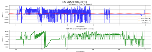
e2e.ti.com/.../adc_5F00_output.txte2e.ti.com/.../adc_5F00_output_5F00_cleaned.txt