This thread has been locked.

If you have a related question, please click the "Ask a related question" button in the top right corner. The newly created question will be automatically linked to this question.

[参考译文] MSP-EXP430FR2355:用于发送字符串的UART不工作

Guru**** 2577385 points
Other Parts Discussed in Thread: MSP-EXP430FR2355

请注意,本文内容源自机器翻译,可能存在语法或其它翻译错误,仅供参考。如需获取准确内容,请参阅链接中的英语原文或自行翻译。

https://e2e.ti.com/support/microcontrollers/msp-low-power-microcontrollers-group/msp430/f/msp-low-power-microcontroller-forum/1098571/msp-exp430fr2355-uart-to-send-a-string-is-not-working

部件号:MSP-EXP430FR2355

我有 MSP-EXP430FR2355印刷电路板A版板。

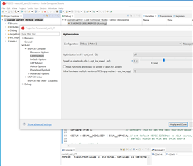
我已经使用Brock LaMeres的著作《嵌入式系统设计》第376页中的以下UART C程序构建了CCS项目

#include <msp430.h> 

void main(void)
{
	WDTCTL = WDTPW | WDTHOLD;	// stop watchdog timer
	
	UCA1CTLW0 |= UCSWRST;


    UCA1CTLW0 |= UCSSEL__SMCLK;
    UCA1BRW = 8;
    UCA1MCTLW |= 0xD600;

    P4SEL1 &= ~BIT3;
    P4SEL0 |= BIT3;

    PM5CTL0 &= ~LOCKLPM5;

    UCA1CTLW0 &= UCSWRST;

    char message[] = "Hello World ";

    int position;
    int i, j;

    while(1)
    {
        for (position=0; position<sizeof(message); position++)
        {
            UCA1TXBUF = message[position];
            for (i=0; i < 100; i=i+1)
            {
                ;
            }
        }
        for (j=0; j<30000; j=j+1)
        {

        }
    }

//	return 0;
}

以上程序将向CCS终端发送"Hello World"字符串。

但没有发送。

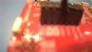
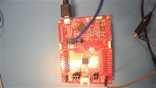
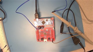
因此,我已卸下跳线RXD并连接到示波器,J101的RDX引脚上没有信号,如以下三幅图像所示。

是什么导致程序不将UART消息字符串发送到CCS终端?

谢谢!

很好

  • 请注意,本文内容源自机器翻译,可能存在语法或其它翻译错误,仅供参考。如需获取准确内容,请参阅链接中的英语原文或自行翻译。

    我建议您从回声示例开始,然后在此处填写工作表。

    此程序有几个问题可能是也可能不是导致您的问题的原因。 例如,延迟环路几乎可以肯定地得到优化。

  • 请注意,本文内容源自机器翻译,可能存在语法或其它翻译错误,仅供参考。如需获取准确内容,请参阅链接中的英语原文或自行翻译。

    除了Keith所说的:

    >UCA1CTLW0 &= UCSWRST;

    这不是您想要的。 请尝试:

    >UCA1CTLW0 &=~UCSWRST;  

    ---------

    TX数据将显示在J101上的TXD引脚处。

  • 请注意,本文内容源自机器翻译,可能存在语法或其它翻译错误,仅供参考。如需获取准确内容,请参阅链接中的英语原文或自行翻译。

    SSJ,您好!  

    我们建议从其中一个代码示例开始,然后再进行修改。

    以下是指向MSP Academy代码示例的链接,该示例是您尝试执行的操作的良好开端: https://dev.ti.com/tirex/explore/node?node=AHhJeKEkk81ZAupK79a2ag__IOGqZri__LATEST

    在此示例中,从PC串行端口接收的字符将回显。  

    此致,  

    Henok

  • 请注意,本文内容源自机器翻译,可能存在语法或其它翻译错误,仅供参考。如需获取准确内容,请参阅链接中的英语原文或自行翻译。

    Hell Henok,Bruce和Keith

    感谢大家的意见和帮助。

    但是 ,FR2355上的euscia0_UART_01程序尚未运行。

    //******************************************************************************
    //  MSP430FR235x Demo -  eUSCI_A0 UART echo at 9600 baud using BRCLK = 8MHz.
    //
    //  Description: This demo echoes back characters received via a PC serial port.
    //  SMCLK/ DCO is used as a clock source and the device is put in LPM3
    //  The auto-clock enable feature is used by the eUSCI and SMCLK is turned off
    //  when the UART is idle and turned on when a receive edge is detected.
    //  Note that level shifter hardware is needed to shift between RS232 and MSP
    //  voltage levels.
    //
    //  The example code shows proper initialization of registers
    //  and interrupts to receive and transmit data.
    //  To test code in LPM3, disconnect the debugger.
    //
    //  ACLK = REFO = 32768Hz, MCLK = DCODIV = SMCLK = 8MHz.
    //
    //                MSP430FR2355
    //             -----------------
    //         /|\|                 |
    //          | |                 |
    //          --|RST              |
    //            |                 |
    //            |                 |
    //            |     P1.7/UCA0TXD|----> PC (echo)
    //            |     P1.6/UCA0RXD|<---- PC
    //            |                 |
    //
    //   Darren Lu
    //   Texas Instruments Inc.
    //   Oct. 2016
    //   Built with IAR Embedded Workbench v6.50 & Code Composer Studio v6.2
    //******************************************************************************
    
    #include <msp430.h>
    
    void Init_GPIO();
    void Software_Trim();                       // Software Trim to get the best DCOFTRIM value
    #define MCLK_FREQ_MHZ 8                     // MCLK = 8MHz
    
    int main(void)
    {
      WDTCTL = WDTPW | WDTHOLD;                // Stop watchdog timer
    
      // Configure GPIO
      Init_GPIO();
    
      PM5CTL0 &= ~LOCKLPM5;                    // Disable the GPIO power-on default high-impedance mode
                                               // to activate 1previously configured port settings
    
      __bis_SR_register(SCG0);                 // disable FLL
      CSCTL3 |= SELREF__REFOCLK;               // Set REFO as FLL reference source
      CSCTL1 = DCOFTRIMEN_1 | DCOFTRIM0 | DCOFTRIM1 | DCORSEL_3;// DCOFTRIM=3, DCO Range = 8MHz
      CSCTL2 = FLLD_0 + 243;                  // DCODIV = 8MHz
      __delay_cycles(3);
      __bic_SR_register(SCG0);                // enable FLL
      Software_Trim();                        // Software Trim to get the best DCOFTRIM value
    
      CSCTL4 = SELMS__DCOCLKDIV | SELA__REFOCLK; // set default REFO(~32768Hz) as ACLK source, ACLK = 32768Hz
                                               // default DCODIV as MCLK and SMCLK source
    
      // Configure UART pins
      P1SEL0 |= BIT6 | BIT7;                    // set 2-UART pin as second function
    
      // Configure UART
      UCA0CTLW0 |= UCSWRST;
      UCA0CTLW0 |= UCSSEL__SMCLK;
    
      // Baud Rate calculation
      // 8000000/(16*9600) = 52.083
      // Fractional portion = 0.083
      // User's Guide Table 17-4: UCBRSx = 0x49
      // UCBRFx = int ( (52.083-52)*16) = 1
      UCA0BR0 = 52;                             // 8000000/16/9600
      UCA0BR1 = 0x00;
      UCA0MCTLW = 0x4900 | UCOS16 | UCBRF_1;
    
      UCA0CTLW0 &= ~UCSWRST;                    // Initialize eUSCI
      UCA0IE |= UCRXIE;                         // Enable USCI_A0 RX interrupt
    
      __bis_SR_register(LPM3_bits|GIE);         // Enter LPM3, interrupts enabled
      __no_operation();                         // For debugger
    }
    
    void Software_Trim()
    {
        unsigned int oldDcoTap = 0xffff;
        unsigned int newDcoTap = 0xffff;
        unsigned int newDcoDelta = 0xffff;
        unsigned int bestDcoDelta = 0xffff;
        unsigned int csCtl0Copy = 0;
        unsigned int csCtl1Copy = 0;
        unsigned int csCtl0Read = 0;
        unsigned int csCtl1Read = 0;
        unsigned int dcoFreqTrim = 3;
        unsigned char endLoop = 0;
    
        do
        {
            CSCTL0 = 0x100;                         // DCO Tap = 256
            do
            {
                CSCTL7 &= ~DCOFFG;                  // Clear DCO fault flag
            }while (CSCTL7 & DCOFFG);               // Test DCO fault flag
    
            __delay_cycles((unsigned int)3000 * MCLK_FREQ_MHZ);// Wait FLL lock status (FLLUNLOCK) to be stable
                                                               // Suggest to wait 24 cycles of divided FLL reference clock
            while((CSCTL7 & (FLLUNLOCK0 | FLLUNLOCK1)) && ((CSCTL7 & DCOFFG) == 0));
    
            csCtl0Read = CSCTL0;                   // Read CSCTL0
            csCtl1Read = CSCTL1;                   // Read CSCTL1
    
            oldDcoTap = newDcoTap;                 // Record DCOTAP value of last time
            newDcoTap = csCtl0Read & 0x01ff;       // Get DCOTAP value of this time
            dcoFreqTrim = (csCtl1Read & 0x0070)>>4;// Get DCOFTRIM value
    
            if(newDcoTap < 256)                    // DCOTAP < 256
            {
                newDcoDelta = 256 - newDcoTap;     // Delta value between DCPTAP and 256
                if((oldDcoTap != 0xffff) && (oldDcoTap >= 256)) // DCOTAP cross 256
                    endLoop = 1;                   // Stop while loop
                else
                {
                    dcoFreqTrim--;
                    CSCTL1 = (csCtl1Read & (~DCOFTRIM)) | (dcoFreqTrim<<4);
                }
            }
            else                                   // DCOTAP >= 256
            {
                newDcoDelta = newDcoTap - 256;     // Delta value between DCPTAP and 256
                if(oldDcoTap < 256)                // DCOTAP cross 256
                    endLoop = 1;                   // Stop while loop
                else
                {
                    dcoFreqTrim++;
                    CSCTL1 = (csCtl1Read & (~DCOFTRIM)) | (dcoFreqTrim<<4);
                }
            }
    
            if(newDcoDelta < bestDcoDelta)         // Record DCOTAP closest to 256
            {
                csCtl0Copy = csCtl0Read;
                csCtl1Copy = csCtl1Read;
                bestDcoDelta = newDcoDelta;
            }
    
        }while(endLoop == 0);                      // Poll until endLoop == 1
    
        CSCTL0 = csCtl0Copy;                       // Reload locked DCOTAP
        CSCTL1 = csCtl1Copy;                       // Reload locked DCOFTRIM
        while(CSCTL7 & (FLLUNLOCK0 | FLLUNLOCK1)); // Poll until FLL is locked
    }
    
    
    #if defined(__TI_COMPILER_VERSION__) || defined(__IAR_SYSTEMS_ICC__)
    #pragma vector=USCI_A0_VECTOR
    __interrupt void USCI_A0_ISR(void)
    #elif defined(__GNUC__)
    void __attribute__ ((interrupt(USCI_A0_VECTOR))) USCI_A0_ISR (void)
    #else
    #error Compiler not supported!
    #endif
    {
      switch(__even_in_range(UCA0IV,USCI_UART_UCTXCPTIFG))
      {
        case USCI_NONE: break;
        case USCI_UART_UCRXIFG:
          while(!(UCA0IFG&UCTXIFG));
          UCA0TXBUF = UCA0RXBUF;
          __no_operation();
          break;
        case USCI_UART_UCTXIFG: break;
        case USCI_UART_UCSTTIFG: break;
        case USCI_UART_UCTXCPTIFG: break;
        default: break;
      }
    }
    
    void Init_GPIO()
    {
        P1DIR = 0xFF; P2DIR = 0xFF;
        P1REN = 0xFF; P2REN = 0xFF;
        P1OUT = 0x00; P2OUT = 0x00;
    }
    

    我关闭了如下所示的优化,运行时进行了优化,但没有优化,两者都没有运行。

    请帮助使这些示例程序在 TI主板上的FR2355和F5438A上工作。

    谢谢,此致,

    很好

  • 请注意,本文内容源自机器翻译,可能存在语法或其它翻译错误,仅供参考。如需获取准确内容,请参阅链接中的英语原文或自行翻译。

    在FR2355和F5438A主板上,数字IO针脚(LED闪烁,使用开关1)工作正常。

    我需要让UART串行通信引脚正常工作。

    谢谢!

  • 请注意,本文内容源自机器翻译,可能存在语法或其它翻译错误,仅供参考。如需获取准确内容,请参阅链接中的英语原文或自行翻译。

    我正在这些方案上取得进展。 我正在将此检查为已解决。

    如果我需要有关此主题/问题的其他信息,我将创建单独的问题。

    谢谢!

    很好