请注意,本文内容源自机器翻译,可能存在语法或其它翻译错误,仅供参考。如需获取准确内容,请参阅链接中的英语原文或自行翻译。
器件型号:MSP430F5529 主题中讨论的其他器件:MSP-EXP430F5529LP
大家好、我不熟悉嵌入式编程。 我从 MSP-EXP430F5529LP 开始、并尝试关注 Chris Svec 的博客系列 embedded.fm/.../ese101
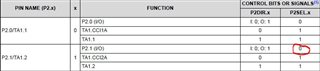
在他的一个博客(embedded.fm/.../ese101-interrupts-blink)中、作者使用 ISR (通过按钮开关 GPIO 1.1触发)使 LED (GPIO 1.0)闪烁。 我遵循他成功完成的操作、然后我想创建另一个 ISR、以使用另一个按钮开关(GPIO 2.1)使另一个 LED (GPIO 4.7)闪烁。
以下是我在汇编语言中的代码:
;-------------------------------------------------------------------------------
; Main loop here
;-------------------------------------------------------------------------------
; Set GPIO P1.0 to be an output (P1DIR bit 0 == 1)
BIS.B #0x01, &P1DIR
; Set GPIO P1.1 to be an input (P1DIR bit 1 == 0)
BIC.B #0x02, &P1DIR
; Set GPIO P1.1 to be pulled up or down (P1REN bit 1 == 1)
BIS.B #0x02, &P1REN
; Set GPIO P1.1 as a pull-up resistor (P1OUT bit 1 == 1)
BIS.B #0x02, &P1OUT

; Set interrupt on high-to-low transition of P1.1
BIS.B #0x02, &P1IES
; Clear any interrupts that happened when changing P1IES
BIC.B #0x02, &P1IFG
; Enable P1.1 interrupts
BIS.B #0x02, &P1IE
;-------------------------------------------------------------------------------
; Set GPIO P4.7 to be an output (P4DIR bit 7 == 1)
BIS.B #0x80, &P4DIR
; Set GPIO P2.1 to be an input (P2DIR bit 1 == 0)
BIC.B #0x02, &P2DIR
; Set GPIO P2.1 to be pulled up or down (P2REN bit 1 == 1)
BIS.B #0x02, &P2REN
; Set GPIO P2.1 as a pull-up resistor (P2OUT bit 1 == 1)
BIS.B #0x02, &P2OUT

; Set interrupt on high-to-low transition of P2.1
BIS.B #0x02, &P2IES
; Clear any interrupts that happened when changing P2IES
BIC.B #0x02, &P2IFG
; Enable P2.1 interrupts
BIS.B #0x02, &P2IE

; Enable interrupts
NOP ; the user’s guide recommends a NOP before setting #GIE
BIS #GIE, SR
NOP ; the user’s guide recommends a NOP after setting #GIE

BIC.W #0x01, &P1OUT
BIC.W #0x80, &P4OUT


MainLoop: ; infinite loop that does nothing
JMP MainLoop
NOP

PORT1_ISR:
; Clear the interrupt flag.
BIC #0x02, &P1IFG
; Toggle GPIO P1.0
XOR.B #0x01, &P1OUT
RETI

PORT2_ISR:
; Clear the interrupt flag.
BIC #0x02, &P2IFG
; Toggle GPIO P4.7
XOR.B #0x80, &P4OUT
RETI

;-------------------------------------------------------------------------------
; Stack Pointer definition
;-------------------------------------------------------------------------------
.global __STACK_END
.sect .stack

;-------------------------------------------------------------------------------
; Interrupt Vectors
;-------------------------------------------------------------------------------
.sect ".reset" ; MSP430 RESET Vector
.short RESET
.sect ".int47" ; We added these two lines
.short PORT1_ISR ; for configuring our GPIO Port P1 ISR.

.sect ".int42"
.short PORT2_ISR
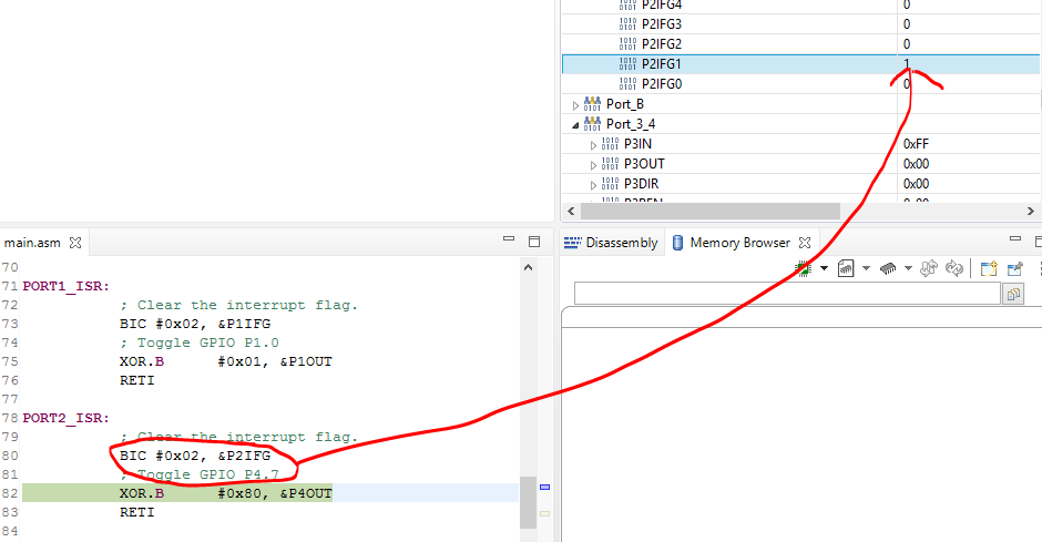
当我在评估板上运行代码时、 它能够完美地适用于 Port1_ISR:。 ISR PORT1_ISR: 在 GPIO 1.1 被接合时执行。 ISR 完成后、它返回到 MainLoop。 但是、当我尝试 port2_ISR 时、GPIO 2.1会触发 ISR、但在完成后、它不会返回到 MainLoop。 相反、它会无限期地在该 ISR 中循环。 我在这里有什么问题吗?
谢谢
Yi