

请注意,本文内容源自机器翻译,可能存在语法或其它翻译错误,仅供参考。如需获取准确内容,请参阅链接中的英语原文或自行翻译。
器件型号:MSP430F6726 #include <msp430.h>
int main(void)
{
WDTCTL = WDTPW | WDTHOLD; // Stop WDT
// Port Mapping
PMAPKEYID = PMAPKEY; // Enable access Port Mapping regs
PMAPCTL |= PMAPRECFG; // Allow reconfiguration of port mapping
P3MAP7 = PM_UCA0TXD; // Map UARTA0 Tx to P3.7
P3MAP6 = PM_UCA0RXD; // Map UARTA0 Rx to P3.6
PMAPKEYID = 0; // Disable access Port Mapping regs
// Setup P3.6 UCA0RXD, P3.7 UCA0TXD
P3SEL |= BIT6 | BIT7; // Set P3.6, P3.7 to non-IO
P3DIR |= BIT6 | BIT7; // Enable UCA0RXD, UCA0TXD
// Setup LFXT1
UCSCTL6 &= ~(XT1OFF); // XT1 On
UCSCTL6 |= XCAP_3; // Internal load cap
// Loop until XT1 fault flag is cleared
do
{
UCSCTL7 &= ~(XT2OFFG | XT1LFOFFG | DCOFFG);
// Clear XT2,XT1,DCO fault flags
SFRIFG1 &= ~OFIFG; // Clear fault flags
} while (SFRIFG1 & OFIFG); // Test oscillator fault flag
// Setup eUSCI_A0
UCA0CTLW0 |= UCSWRST; // **Put state machine in reset**
UCA0CTLW0 |= UCSSEL_2; // SMCLK
UCA0BRW_L = 6; // 1MHz 9600 (see User's Guide)
UCA0BRW_H = 0; // 1MHz 9600
UCA0MCTLW = UCBRF_13 | UCOS16; // Modln UCBRSx=0, UCBRFx=0x13,
// over sampling
UCA0CTLW0 &= ~UCSWRST; // **Initialize USCI state machine**
UCA0IE |= UCRXIE; // Enable USCI_A0 RX interrupt
__bis_SR_register(LPM0_bits | GIE); // Enter LPM0, interrupts enabled
__no_operation(); // For debugger
}
// USCI_A0 interrupt service routine
#pragma vector=USCI_A0_VECTOR
__interrupt void USCI_A0_ISR(void)
{
switch (__even_in_range(UCA0IV, 4))
{
case USCI_NONE: break; // No interrupt
case USCI_UART_UCRXIFG: // RXIFG
while (!(UCA0IFG & UCTXIFG)) ; // USCI_A0 TX buffer ready?
UCA0TXBUF = UCA0RXBUF; // TX -> RXed character
break;
case USCI_UART_UCTXIFG: break; // TXIFG
case USCI_UART_UCSTTIFG: break; // TTIFG
case USCI_UART_UCTXCPTIFG: break; // TXCPTIFG
default: break;
}
}
我使用 MSP430F673X_USCIA0_UART_04.c 示例、只是添加了端口映射配置。 但它看起来不能正常工作。
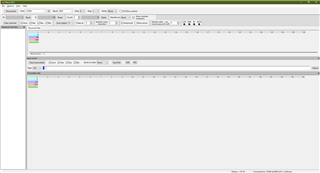
我在过去的3天里一直在尝试它。 我尝试使用不同的 clk 配置。 它的最佳工作方式是上面的代码、它的输出与上面的 img 相同。
