Other Parts Discussed in Thread: MSP430FR2355
请注意,本文内容源自机器翻译,可能存在语法或其它翻译错误,仅供参考。如需获取准确内容,请参阅链接中的英语原文或自行翻译。
主题中讨论的其他器件:MSP430FR2355大家好、
我使用 MSP430FR2355控制器、同时希望通过 I2C 读取和写入 EEPROM。 在使用其他控制器之前、我不熟悉 MSP 控制器。
出于测试目的、我使用了 TI 的示例 Eusci_b_I2C_ex4_masterTXMultiple。
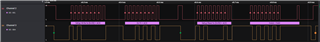
我已经配置了 IO_Ports、因此我已经可以发送一些内容。 也就是说、如果我使用 EUSCI_B_I2C_masterSendMultiByteStart 函数并发送0x50作为数据、例如、它永远不会工作。 数据0x21始终显示在逻辑分析仪中。 无论我希望通过此函数发送什么数据。 我还使用了示例 Eusci_b_i2c_masterTXSingle、我遇到了相同的问题。 有人知道问题是什么、可以帮助我吗? 我还使用了该示例、它始终发送0x21。
感谢你的帮助

#include "driverlib.h"
#include "Board.h"
#include <stdint.h>
#include "I2C/I2C_Interface.h"
//*****************************************************************************
//
//Set the address for slave module. This is a 7-bit address sent in the
//following format:
//[A6:A5:A4:A3:A2:A1:A0:RS]
//
//A zero in the "RS" position of the first byte means that the master
//transmits (sends) data to the selected slave, and a one in this position
//means that the master receives data from the slave.
//
//*****************************************************************************
#define SLAVE_ADDRESS 0b10100001
#define EEPROM_Address_R 0b10100001//0xA1 ///A1 A3 AF AD
#define EEPROM_Address_W 0b10100000//0xA0 ///A0 A2 AE AC
unsigned char EEPROM_Read(unsigned int add); //Random Address Read
//*****************************************************************************
//
//Target frequency for SMCLK in kHz
//
//*****************************************************************************
#define CS_SMCLK_DESIRED_FREQUENCY_IN_KHZ 1000
//*****************************************************************************
//
//SMCLK/FLLRef Ratio
//
//*****************************************************************************
#define CS_SMCLK_FLLREF_RATIO 30
// Pointer to TX data
uint8_t TXData = 0;
uint8_t TXByteCtr;
void main(void)
{
WDT_A_hold(WDT_A_BASE);
//Set DCO FLL reference = REFO
CS_initClockSignal(
CS_FLLREF,
CS_REFOCLK_SELECT,
CS_CLOCK_DIVIDER_1
);
//Set Ratio and Desired MCLK Frequency and initialize DCO
CS_initFLLSettle(
CS_SMCLK_DESIRED_FREQUENCY_IN_KHZ,
CS_SMCLK_FLLREF_RATIO
);
//Set ACLK = VLO with frequency divider of 1
CS_initClockSignal(
CS_ACLK,
CS_VLOCLK_SELECT,
CS_CLOCK_DIVIDER_1
);
//Set SMCLK = DCO with frequency divider of 1
CS_initClockSignal(
CS_SMCLK,
CS_DCOCLKDIV_SELECT,
CS_CLOCK_DIVIDER_1
);
//Set MCLK = DCO with frequency divider of 1
CS_initClockSignal(
CS_MCLK,
CS_DCOCLKDIV_SELECT,
CS_CLOCK_DIVIDER_1
);
// Configure Pins for I2C
GPIO_setAsPeripheralModuleFunctionInputPin(
GPIO_PORT_UCB0SCL,
GPIO_PIN_UCB0SCL,
GPIO_FUNCTION_UCB0SCL
);
GPIO_setAsPeripheralModuleFunctionInputPin(
GPIO_PORT_UCB0SDA,
GPIO_PIN_UCB0SDA,
GPIO_FUNCTION_UCB0SDA
);
/*
* Disable the GPIO power-on default high-impedance mode to activate
* previously configured port settings
*/
PMM_unlockLPM5();
EUSCI_B_I2C_initMasterParam param = {0};
param.selectClockSource = EUSCI_B_I2C_CLOCKSOURCE_SMCLK;
param.i2cClk = CS_getSMCLK();
param.dataRate = EUSCI_B_I2C_SET_DATA_RATE_400KBPS;
param.byteCounterThreshold = 0;
param.autoSTOPGeneration = EUSCI_B_I2C_NO_AUTO_STOP;
EUSCI_B_I2C_initMaster(EUSCI_B0_BASE, ¶m);
//Specify slave address
EUSCI_B_I2C_setSlaveAddress(EUSCI_B0_BASE,
SLAVE_ADDRESS
);
//Set Master in receive mode
EUSCI_B_I2C_setMode(EUSCI_B0_BASE,
EUSCI_B_I2C_TRANSMIT_MODE
);
//Enable I2C Module to start operations
EUSCI_B_I2C_enable(EUSCI_B0_BASE);
EUSCI_B_I2C_clearInterrupt(EUSCI_B0_BASE,
EUSCI_B_I2C_TRANSMIT_INTERRUPT0 +
EUSCI_B_I2C_NAK_INTERRUPT
);
//Enable master Receive interrupt
EUSCI_B_I2C_enableInterrupt(EUSCI_B0_BASE,
EUSCI_B_I2C_TRANSMIT_INTERRUPT0 +
EUSCI_B_I2C_NAK_INTERRUPT
);
// while(1)
// {
__delay_cycles(500); // Delay between transmissions
// TXByteCtr = 4; // Load TX byte counter
// TXData = 0;
while (EUSCI_B_I2C_SENDING_STOP == EUSCI_B_I2C_masterIsStopSent(EUSCI_B0_BASE));
EUSCI_B_I2C_masterSendMultiByteStart(EUSCI_B0_BASE, 0x50);
EUSCI_B_I2C_masterSendMultiByteStart(EUSCI_B0_BASE, 0x47);
EUSCI_B_I2C_masterSendMultiByteStart(EUSCI_B0_BASE, 0x32);
//__bis_SR_register(CPUOFF + GIE); // Enter LPM0 w/ interrupts
// Remain in LPM0 until all data
// is TX'd
// Increment data byte
// }
while(1)
{}
}
//------------------------------------------------------------------------------
// The USCIAB0TX_ISR is structured such that it can be used to transmit any
// number of bytes by pre-loading TXByteCtr with the byte count. Also, TXData
// points to the next byte to transmit.
//------------------------------------------------------------------------------
#if defined(__TI_COMPILER_VERSION__) || defined(__IAR_SYSTEMS_ICC__)
#pragma vector=USCI_B0_VECTOR
__interrupt
#elif defined(__GNUC__)
__attribute__((interrupt(USCI_B0_VECTOR)))
#endif
void USCIB0_ISR(void)
{
switch(__even_in_range(UCB0IV, USCI_I2C_UCBIT9IFG))
{
case USCI_NONE: // No interrupts break;
break;
case USCI_I2C_UCALIFG: // Arbitration lost
break;
case USCI_I2C_UCNACKIFG: // NAK received (master only)
//resend start if NACK
EUSCI_B_I2C_masterSendStart(EUSCI_B0_BASE);
break;
case USCI_I2C_UCTXIFG0: // TXIFG0
// Check TX byte counter
// if (TXByteCtr)
// {
// EUSCI_B_I2C_masterSendMultiByteNext(EUSCI_B0_BASE, TXData++);
// // Decrement TX byte counter
// TXByteCtr--;
// }
// else
// {
// EUSCI_B_I2C_masterSendMultiByteStop(EUSCI_B0_BASE);
// // Exit LPM0
// __bic_SR_register_on_exit(CPUOFF);
// }
break;
default:
break;
}
}