Other Parts Discussed in Thread: TMP102, MSP430FR2433, TMP112
请注意,本文内容源自机器翻译,可能存在语法或其它翻译错误,仅供参考。如需获取准确内容,请参阅链接中的英语原文或自行翻译。
器件型号:MSP430FR2433 主题中讨论的其他器件:TMP102、 TMP112
工具/软件:Code Composer Studio
尊敬的团队:
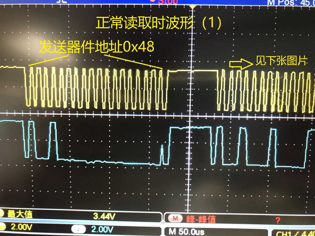
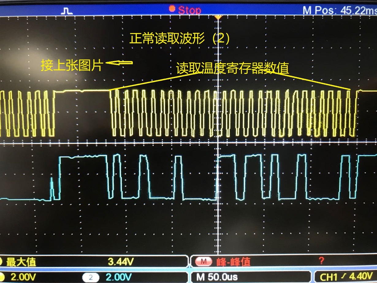
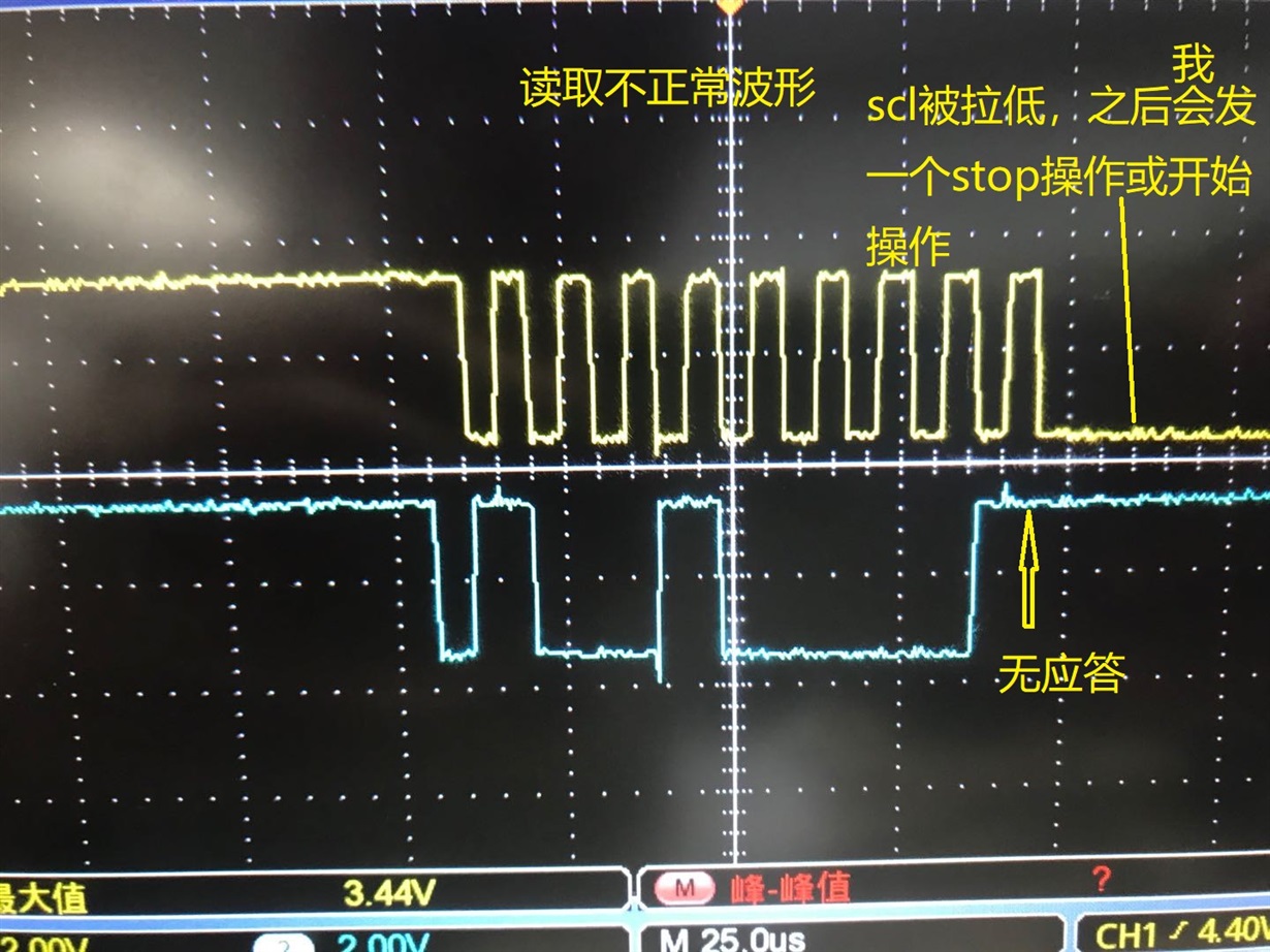
我的客户正在将 MSP430FR2433与 TMP102/TMP112搭配使用。
温度变化缓慢时、响应正常。
但是、 当温度在特定时间段内大幅变化(例如热空气吹出时)时、将不会有响应、一段时间后会更好。
没有这种现象的其他 MCU (AVR)。 SDA\SCL 引脚全部通过10K 电阻器上拉、频率约为100K。
请帮助。
#include
#include
#include
#include
#define TIMEOUT 60000

void i2c_init (void){
静态 char init=0;
if (!init){
P1REN |= BIT2 | BIT3;
P1OUT |= BIT2 | BIT3;

//如果总线被卡住(SDA =低电平):时钟直到它恢复
P1DIR |= BIT3;
while (!(P1IN & BIT2)){
P1OUT |= BIT3;
_DELAY_CYCLES (8*80);
P1OUT &=~BIT3;
__DELAY_CYCLES (8*80);
}

P1SEL0 |= BIT2 | BIT3; // I2C 引脚
//将 USCI_B0配置为 I2C 模式
UCB0CTLW0 |= UCSWRST; //软件复位被启用
UCB0CTLW0 |= UCMODE_3 | UCMST | UCSYNC;// I2C 模式、主控模式、同步
//到达 UCB0TBCNT 后
UCB0BRW = 10; //波特率= SMCLK / 10 =~100K
UCB0CTL1 &=~UCSWRST;
INIT = 1;
}
}

int i2c_senddata (char *数据,int len){
unsigned int timeout=0;
unsigned int i;
静态 int 虚拟=0;
/*if (dummy){
UCB0TXBUF = 0;
超时= 0;
while (!(UCB0IFG & UCTXIFG0))
if (timeout++>超时)
返回-1;
}
if (dummy = 0) dummy = 1;
*/
//__delay_cycles (5000);
for (i=0;i 超时)
返回3;
}
返回0;
}

int i2c_ReadData (char *数据、int len){
unsigned int timeout=0;
unsigned int i;

memset (data、0、len);
for (i=0;i 超时)
返回-1;


DATA[i]= UCB0RXBUF;
如果(len > 1)
if (i == len-2)
UCB0CTLW0 |= UCTR | UCTXSTP;

}
//while (!(UCB0IFG & UCTXIFG0));
返回0;
}

int i2c_start (char addr、int read){
unsigned int timeout=0;
UCB0I2CSA = addr;
if (读)
UCB0CTLW0 &=~UCTR;
其他
UCB0CTLW0 |= UCTR;
while (UCB0CTL1 & UCTXSTP);
UCB0CTLW0 |= UCTXSTT; // I2C TX、启动条件

while (!(UCB0IFG & UCTXIFG0))
if (timeout++>超时)
返回1;

IF (UCB0IFG 和 UCNACKIFG)
{
UCB0CTL1 |= UCTXSTP; // I2C 启动条件
UCB0IFG = 0; //清除所有 USCI_B0标志
返回2; //检查 NACK
}

if (!read){
UCB0TXBUF = 0;
while (!(UCB0IFG & UCTXIFG0));
}

返回0;
}

int i2c_start2 (char addr、int read){
unsigned int timeout=0;
UCB0I2CSA = addr;
if (读)
UCB0CTLW0 &=~UCTR;
其他
UCB0CTLW0 |= UCTR;
while (UCB0CTL1 & UCTXSTP);
UCB0CTLW0 |= UCTXSTT; // I2C TX、启动条件

while (!(UCB0IFG & UCTXIFG0))
{
if (timeout++>超时)
返回5;
}

IF (UCB0IFG 和 UCNACKIFG)
{
UCB0CTL1 |= UCTXSTP; // I2C 启动条件
UCB0IFG = 0; //清除所有 USCI_B0标志
返回6; //检查 NACK
}

/*if (!read){
UCB0TXBUF = d;
while (!(UCB0IFG & UCTXIFG0));
}*/

返回0;
}

int i2c_stop (void){
unsigned int timeout=0;
UCB0CTLW0 |= UCTR | UCTXSTP; // I2C TX、停止条件
while (UCB0IFG 和 UCTXSTP)
if (timeout++>超时)
返回4;
返回0;
}

int read_reg (int address、int reg){
Int 错误;
char buf[2]={reg};
ERR = i2c_start2 (地址、0);
if (err!= 0) return err;
ERR = i2c_senddata (buf、1);
if (err!= 0) return err;
ERR = i2c_stop ();
if (err!= 0) return err;
_delay_cycles (10000); 等待转换完成 μ s
ERR = i2c_start2 (地址、1);
if (err!= 0) return err;
ERR = i2c_ReadData (buf、2);
if (err!= 0) return err;
返回 buf[0]<<8|buf[1];

}

void write_reg (int address、int reg、int value){
char buf[2]={reg、value};
I2C_start2 (地址、0);
I2C_senddata (buf、2);
I2C_STOP();
}


void tmp117_init (void){
i2C_init();
}

int tmp117_gettemp (void)
{
unsigned int tmp117_raw = 0;
float t = 0;
tmp117_raw = read_reg (0x48、0);
tmp117_raw >= 4;

if (tmp117_raw <= 0x7ff){

t= tmp117_raw * 6.25;

}
if (tmp117_ray>=0xc90){
tmp117_raw =~tmp117_raw;
tmp117_raw &=0x0fff;
tmp117_raw +=1;
t= tmp117_ray*6.25;
t =-t;
}
返回(int)t;
}