


请注意,本文内容源自机器翻译,可能存在语法或其它翻译错误,仅供参考。如需获取准确内容,请参阅链接中的英语原文或自行翻译。
器件型号:MSP430F6435 主题中讨论的其他器件: MSP430F6638
大家好。
我正在尝试在 MSP430F6435IPZ 上实现 I2C。
由于这是我第一次使用 I2C、我从 Resource Explorer 获取了 msp430f66xx_USCI_i2c_standard_master.c 以供参考。
在 GPIO 初始化函数中
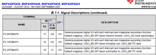
P2MAP0 = PM_UCB0SDA;
P2MAP1 = PM_UCB.S.;
但 MSP430F6435数据表指出 P2MAP1是 I2C 数据、P2MAP2是时钟。
(MSP430F6638具有相同的映射。)
为什么它的设置方式与基准类似?
参考函数如下。
void initGPIO()
{
// LED
LED_OUT 且=~LED_PIN;// P1用于 LED 和 RESET 输出的设置
LED_DIR |= LED_PIN;
//更改端口映射寄存器之前禁用中断
_disable_interrupt ();
//启用写访问以修改端口映射寄存器
PMAPPWD = 0x02D52;
//I2C 引脚
P2SEL |= BIT0 | BIT1;
P2MAP0 = PM_UCB0SDA;
P2MAP1 = PM_UCB.S.;
//禁用写访问以修改端口映射寄存器
PMAPPWD = 0;
}
