

请注意,本文内容源自机器翻译,可能存在语法或其它翻译错误,仅供参考。如需获取准确内容,请参阅链接中的英语原文或自行翻译。
器件型号:MSP430FR2433 主题中讨论的其他器件: MSP430WARE
您好!
我使用的 MSP430FR2433使用的是 msp430ware 版本3.80.14.01、对 I2C 的工作原理很好奇、
因此、通过恢复在示波器中检查了引脚 P1.3和 P1.2、示波器中看不到这两个选项。
如下图所示:
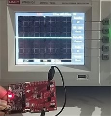
我想知道为什么不会生成时钟和数据信号。
这在从器件未连接时执行、
在调试模式下暂停时、它正在按照"eusci_b_i2c.c"文件的指令运行
//Poll for transmit interrupt flag.
    while (!(HWREG16(baseAddress + OFS_UCBxIFG) & UCTXIFG)) ;
示例( eusci_b_i2c_ex3_masterTxMultiple )代码、我在此中使用的代码如下:
// Demo - EUSCI_B0 I2C Master TX multiple bytes to MSP430 Slave
#define SLAVE_ADDRESS 0x48
//*****************************************************************************
//
//Target frequency for SMCLK in kHz
//
//*****************************************************************************
#define CS_SMCLK_DESIRED_FREQUENCY_IN_KHZ 1000
//*****************************************************************************
//
//SMCLK/FLLRef Ratio
//
//*****************************************************************************
#define CS_SMCLK_FLLREF_RATIO 30
// Pointer to TX data
uint8_t TXData = 0;
uint8_t TXByteCtr;
void main(void)
{
WDT_A_hold(WDT_A_BASE);
//Set DCO FLL reference = REFO
CS_initClockSignal(
CS_FLLREF,
CS_REFOCLK_SELECT,
CS_CLOCK_DIVIDER_1
);
//Set Ratio and Desired MCLK Frequency and initialize DCO
CS_initFLLSettle(
CS_SMCLK_DESIRED_FREQUENCY_IN_KHZ,
CS_SMCLK_FLLREF_RATIO
);
//Set ACLK = VLO with frequency divider of 1
CS_initClockSignal(
CS_ACLK,
CS_VLOCLK_SELECT,
CS_CLOCK_DIVIDER_1
);
//Set SMCLK = DCO with frequency divider of 1
CS_initClockSignal(
CS_SMCLK,
CS_DCOCLKDIV_SELECT,
CS_CLOCK_DIVIDER_1
);
//Set MCLK = DCO with frequency divider of 1
CS_initClockSignal(
CS_MCLK,
CS_DCOCLKDIV_SELECT,
CS_CLOCK_DIVIDER_1
);
// Configure Pins for I2C
GPIO_setAsPeripheralModuleFunctionInputPin(
GPIO_PORT_UCB0SCL,
GPIO_PIN_UCB0SCL,
GPIO_FUNCTION_UCB0SCL
);
GPIO_setAsPeripheralModuleFunctionInputPin(
GPIO_PORT_UCB0SDA,
GPIO_PIN_UCB0SDA,
GPIO_FUNCTION_UCB0SDA
);
/*
* Disable the GPIO power-on default high-impedance mode to activate
* previously configured port settings
*/
PMM_unlockLPM5();
EUSCI_B_I2C_initMasterParam param = {0};
param.selectClockSource = EUSCI_B_I2C_CLOCKSOURCE_SMCLK;
param.i2cClk = CS_getSMCLK();
param.dataRate = EUSCI_B_I2C_SET_DATA_RATE_400KBPS;
param.byteCounterThreshold = 0;
param.autoSTOPGeneration = EUSCI_B_I2C_NO_AUTO_STOP;
EUSCI_B_I2C_initMaster(EUSCI_B0_BASE, ¶m);
//Specify slave address
EUSCI_B_I2C_setSlaveAddress(EUSCI_B0_BASE,
SLAVE_ADDRESS
);
//Set Master in receive mode
EUSCI_B_I2C_setMode(EUSCI_B0_BASE,
EUSCI_B_I2C_TRANSMIT_MODE
);
//Enable I2C Module to start operations
EUSCI_B_I2C_enable(EUSCI_B0_BASE);
EUSCI_B_I2C_clearInterrupt(EUSCI_B0_BASE,
EUSCI_B_I2C_TRANSMIT_INTERRUPT0 +
EUSCI_B_I2C_NAK_INTERRUPT
);
//Enable master Receive interrupt
EUSCI_B_I2C_enableInterrupt(EUSCI_B0_BASE,
EUSCI_B_I2C_TRANSMIT_INTERRUPT0 +
EUSCI_B_I2C_NAK_INTERRUPT
);
while(1)
{
__delay_cycles(1000); // Delay between transmissions
TXByteCtr = 4; // Load TX byte counter
TXData = 0;
while (EUSCI_B_I2C_SENDING_STOP == EUSCI_B_I2C_masterIsStopSent(EUSCI_B0_BASE));
EUSCI_B_I2C_masterSendMultiByteStart(EUSCI_B0_BASE, TXData++);
__bis_SR_register(CPUOFF + GIE); // Enter LPM0 w/ interrupts
// Remain in LPM0 until all data
// is TX'd
// Increment data byte
}
}
//------------------------------------------------------------------------------
// The USCIAB0TX_ISR is structured such that it can be used to transmit any
// number of bytes by pre-loading TXByteCtr with the byte count. Also, TXData
// points to the next byte to transmit.
//------------------------------------------------------------------------------
#if defined(__TI_COMPILER_VERSION__) || defined(__IAR_SYSTEMS_ICC__)
#pragma vector=USCI_B0_VECTOR
__interrupt
#elif defined(__GNUC__)
__attribute__((interrupt(USCI_B0_VECTOR)))
#endif
void USCIB0_ISR(void)
{
switch(__even_in_range(UCB0IV, USCI_I2C_UCBIT9IFG))
{
case USCI_NONE: // No interrupts break;
break;
case USCI_I2C_UCALIFG: // Arbitration lost
break;
case USCI_I2C_UCNACKIFG: // NAK received (master only)
//resend start if NACK
EUSCI_B_I2C_masterSendStart(EUSCI_B0_BASE);
break;
case USCI_I2C_UCTXIFG0: // TXIFG0
// Check TX byte counter
if (TXByteCtr)
{
EUSCI_B_I2C_masterSendMultiByteNext(EUSCI_B0_BASE, TXData++);
// Decrement TX byte counter
TXByteCtr--;
}
else
{
EUSCI_B_I2C_masterSendMultiByteStop(EUSCI_B0_BASE);
// Exit LPM0
__bic_SR_register_on_exit(CPUOFF);
}
break;
default:
break;
}
}
在使用 MasterTxSingle 示例进行该检查后、也不会生成 SCL (CLOCK)。
寻找对上述内容的见解。
谢谢。此致、
Ajaykumar V
