This thread has been locked.

If you have a related question, please click the "Ask a related question" button in the top right corner. The newly created question will be automatically linked to this question.

[参考译文] MSP430F5171:ACLK 神秘

Guru**** 657930 points
请注意,本文内容源自机器翻译,可能存在语法或其它翻译错误,仅供参考。如需获取准确内容,请参阅链接中的英语原文或自行翻译。

https://e2e.ti.com/support/microcontrollers/msp-low-power-microcontrollers-group/msp430/f/msp-low-power-microcontroller-forum/1299071/msp430f5171-aclk-mystery

器件型号:MSP430F5171

我正在使用 该器件的看门狗计时器和 ACLK (看门狗的标准 WDT_ADLY_1000配置以提供1秒的中断)进行简单的计时、但我注意到 与确切 时间有很大偏差(每天最多3分钟)。

最初我在 XIN XOUT 上用的是32.768kHz 晶振、我换了另一个晶振、有负载电容、但仍然有这个重要的偏差、把这个故障放在了晶振上、买了一个25ppm 的参考时钟。 因此、现在我使用该时钟(3.3V、理想值为32768Hz)输入 XIN、但我仍然观察到相同的时间偏差。

经过深入研究、我发现 ACLK 输出与 XIN 信号无关;换句话说、无论我做什么、REF0CLK 信号都被用作 ACLK。

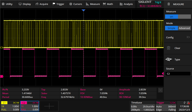
我附上了两个示波器屏幕截图、第一个在 XIN 输入上同步、第二个在 ACLK 输出上同步。

当然、我将 USCTL4配置为0 SELA 以选择 XT1 CLK、并将 USCTL6配置为 XT1BYPASS、并使用调试器确认了这些设置。

所以,在这一点上,我不知道什么可能是错的,任何帮助将会 非常感激!

XIN 信号(黄色) ACLK (粉色)、XIN 为32768Hz

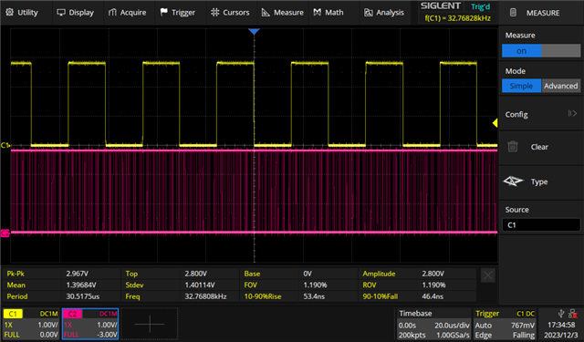
相同、但在 ACLK 上同步、ACLK 的频率为32679Hz

  • 请注意,本文内容源自机器翻译,可能存在语法或其它翻译错误,仅供参考。如需获取准确内容,请参阅链接中的英语原文或自行翻译。

    /* --COPYRIGHT--,BSD_EX
     * Copyright (c) 2012, Texas Instruments Incorporated
     * All rights reserved.
     *
     * Redistribution and use in source and binary forms, with or without
     * modification, are permitted provided that the following conditions
     * are met:
     *
     * *  Redistributions of source code must retain the above copyright
     *    notice, this list of conditions and the following disclaimer.
     *
     * *  Redistributions in binary form must reproduce the above copyright
     *    notice, this list of conditions and the following disclaimer in the
     *    documentation and/or other materials provided with the distribution.
     *
     * *  Neither the name of Texas Instruments Incorporated nor the names of
     *    its contributors may be used to endorse or promote products derived
     *    from this software without specific prior written permission.
     *
     * THIS SOFTWARE IS PROVIDED BY THE COPYRIGHT HOLDERS AND CONTRIBUTORS "AS IS"
     * AND ANY EXPRESS OR IMPLIED WARRANTIES, INCLUDING, BUT NOT LIMITED TO,
     * THE IMPLIED WARRANTIES OF MERCHANTABILITY AND FITNESS FOR A PARTICULAR
     * PURPOSE ARE DISCLAIMED. IN NO EVENT SHALL THE COPYRIGHT OWNER OR
     * CONTRIBUTORS BE LIABLE FOR ANY DIRECT, INDIRECT, INCIDENTAL, SPECIAL,
     * EXEMPLARY, OR CONSEQUENTIAL DAMAGES (INCLUDING, BUT NOT LIMITED TO,
     * PROCUREMENT OF SUBSTITUTE GOODS OR SERVICES; LOSS OF USE, DATA, OR PROFITS;
     * OR BUSINESS INTERRUPTION) HOWEVER CAUSED AND ON ANY THEORY OF LIABILITY,
     * WHETHER IN CONTRACT, STRICT LIABILITY, OR TORT (INCLUDING NEGLIGENCE OR
     * OTHERWISE) ARISING IN ANY WAY OUT OF THE USE OF THIS SOFTWARE,
     * EVEN IF ADVISED OF THE POSSIBILITY OF SUCH DAMAGE.
     *
     *******************************************************************************
     * 
     *                       MSP430 CODE EXAMPLE DISCLAIMER
     *
     * MSP430 code examples are self-contained low-level programs that typically
     * demonstrate a single peripheral function or device feature in a highly
     * concise manner. For this the code may rely on the device's power-on default
     * register values and settings such as the clock configuration and care must
     * be taken when combining code from several examples to avoid potential side
     * effects. Also see www.ti.com/grace for a GUI- and www.ti.com/msp430ware
     * for an API functional library-approach to peripheral configuration.
     *
     * --/COPYRIGHT--*/
    //******************************************************************************
    //  MSP430F51x2 Demo - XT1 sources ACLK
    //
    //  Description: This program demonstrates using XT1 to source ACLK
    //  ACLK = LFXT1 = 32,768Hz	
    //  //* An external watch crystal between XIN & XOUT is required for ACLK *//	
    //
    //               MSP430F51x2
    //             -----------------
    //        /|\ |              XIN|-
    //         |  |                 | 32kHz
    //         ---|RST          XOUT|-
    //            |                 |
    //            |             P3.0|-->ACLK = ~10kHz
    //            |                 |
    //
    //   Bhargavi Nisarga
    //   Texas Instruments Inc.
    //   Dec 2009
    //   Built with CCS v4 and IAR Embedded Workbench Version: 4.21
    //******************************************************************************
    #include <msp430.h>
    
    void Port_Mapping(void);
    
    int main(void)
    {
      WDTCTL = WDTPW + WDTHOLD;                 // Stop WDT
      Port_Mapping();
    
      P3DIR |= BIT0;                            // P3.0=ACLK set out to pins
      P3SEL |= BIT0; 
      PJSEL |= BIT4+BIT5;                       // Port select XT1
    
      UCSCTL6 &= ~(XT1OFF);                     // XT1 On
      UCSCTL6 |= XCAP_3;                        // Internal load cap
      UCSCTL3 = 0;                              // FLL Reference Clock = XT1
    
      // Loop until XT2 & DCO stabilizes - In this case loop until XT1 and DCo settle
      do
      {
        UCSCTL7 &= ~(XT1LFOFFG + XT1HFOFFG + DCOFFG);
                                                // Clear XT1,DCO fault flags
        SFRIFG1 &= ~OFIFG;                      // Clear fault flags
      }while (SFRIFG1&OFIFG);                   // Test oscillator fault flag
      
      UCSCTL6 &= ~(XT1DRIVE_3);                 // Xtal is now stable, reduce drive strength
    
      UCSCTL4 |= SELA_0;                        // ACLK = LFTX1 (by default)
      
      __bis_SR_register(LPM3_bits);             // Enter LPM3
      __no_operation();                         // For debugger
    }
    
    void Port_Mapping(void)
    {
      __disable_interrupt();                    // Disable Interrupts before altering Port Mapping registers
      PMAPPWD = 0x02D52;                        // Enable Write-access to modify port mapping registers
      
      #ifdef PORT_MAP_RECFG                     
      PMAPCTL = PMAPRECFG;                      // Allow reconfiguration during runtime
      #endif  
      
      P3MAP0 = PM_TD1OUTH;
      
      PMAPPWD = 0;                              // Disable Write-Access to modify port mapping registers
      #ifdef PORT_MAP_EINT
      __enable_interrupt();                     // Re-enable all interrupts
      #endif  
    }
    

    您能否直接尝试此示例代码?

  • 请注意,本文内容源自机器翻译,可能存在语法或其它翻译错误,仅供参考。如需获取准确内容,请参阅链接中的英语原文或自行翻译。

    您好、Eason、  

    感谢你的帮助。 当然、我可以实现这一点、但我需要移除连接到 XIN 的参考时钟、然后重新焊接晶体;如果我认为这有助于解决问题、我也会这样做。 但是、我无法看到 此修改如何帮助解决我的问题。 我的基准时钟具有低阻抗和高精度、因此易于布线、使用 XIN 上的晶体不是很容易。

    我有一个时钟输入和一个 ACLK 输出(在端口 PJ.3上)、问题似乎是 ACLK 不是由 XT1提供、而是由 REF0CLK 提供。 我看不到您的示例如何帮助您找出原因;您能解释一下吗?

  • 请注意,本文内容源自机器翻译,可能存在语法或其它翻译错误,仅供参考。如需获取准确内容,请参阅链接中的英语原文或自行翻译。

    我模糊地记得、在 F5系列上、只要 OFIFG 仍被置位、XT1就不会重新启用。 [这似乎也与 UG (SLAU208Q)第172页上的"注释:故障逻辑"一致。]

    您是否使用 OFIFG 完成了清除和轮询循环?

  • 请注意,本文内容源自机器翻译,可能存在语法或其它翻译错误,仅供参考。如需获取准确内容,请参阅链接中的英语原文或自行翻译。

    好的、我只清除了 XT1LFOFFG、清除 OFIFG 解决了问题。 谢谢!

  • 请注意,本文内容源自机器翻译,可能存在语法或其它翻译错误,仅供参考。如需获取准确内容,请参阅链接中的英语原文或自行翻译。

    清除所有振荡器故障标志可修复问题、感谢您的帮助。