This thread has been locked.

If you have a related question, please click the "Ask a related question" button in the top right corner. The newly created question will be automatically linked to this question.

[参考译文] MSP430FR2532:在定制电路板上优化功耗时出现的问题

Guru**** 663810 points
Other Parts Discussed in Thread: MSP430FR2532, ENERGYTRACE
请注意,本文内容源自机器翻译,可能存在语法或其它翻译错误,仅供参考。如需获取准确内容,请参阅链接中的英语原文或自行翻译。

https://e2e.ti.com/support/microcontrollers/msp-low-power-microcontrollers-group/msp430/f/msp-low-power-microcontroller-forum/1308810/msp430fr2532-issue-with-optimising-power-consumption-on-custom-board

器件型号:MSP430FR2532

大家好!

我希望能找到解决我的问题的方法。

我使用的是 MSP430FR2532微控制器(定制设计板)和单个键盘传感器。

关于键盘传感器设计、我遵循了 TI 的设计指南。

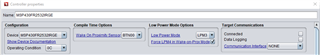
为了测试设计、我使用了 TI 在 CapTIvate 设计中心提供的超低功耗4按钮 FR2633代码(修改为单个按钮)。

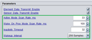
Touch 能够很好地使用代码中提供的默认参数、并且我正在尝试优化功耗。

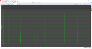
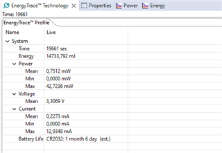
我正在使用 CapTIvate FR2633电能跟踪来检查功耗、我实现的最好方法是28天(采用 CR2032电池设置)。

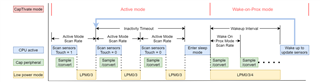
参考 TI 文档、我预计需要3年(基于6uA i-avg/电极)、单按钮和接近唤醒功能以及外部晶体。

我可能缺少一些简单的东西、如果有一些关于如何解决的指导/步骤、我会很感激。 请告诉我您需要什么进一步的信息。

提前感谢。

  • 请注意,本文内容源自机器翻译,可能存在语法或其它翻译错误,仅供参考。如需获取准确内容,请参阅链接中的英语原文或自行翻译。

    尊敬的 Ty:

    在我这边、我认为低功耗模式将对这方面有很大的影响、您使用的是哪一种?

    您能给我提供文档的链接吗?我也可以查看说明。

    B.R.

    萨尔

  • 请注意,本文内容源自机器翻译,可能存在语法或其它翻译错误,仅供参考。如需获取准确内容,请参阅链接中的英语原文或自行翻译。

    您好、Sal、感谢您的回复。

    关于第一个问题、我附上了代码。 我通过 P2.7 (代码中标记为 LED)驱动 TPS 开关。 P1.0上的 LED 未激活。 我还添加了延迟、使 TPS 保持一小段时间。

    void main(void)
    {
        //
        // Initialize the MCU
        // BSP_configureMCU() sets up the device IO and clocking
        // The global interrupt enable is set to allow peripherals
        // to wake the MCU.
        //
        WDTCTL = WDTPW | WDTHOLD;
        BSP_configureMCU();
        __bis_SR_register(GIE);
    
        //
        // Start the CapTIvate application
        //
        CAPT_appStart();
    
        //
        // Background Loop
        //
        while(1)
        {
            //
            // Run the captivate application handler.
            // Set LED1 while the app handler is running,
            // and set LED2 if proximity is detected
            // on any sensor.
            //
            LED1_TOGGLE;
            if(CAPT_appHandler() == true)
            {
                LED2_ON;
    
                // Add delay for 5 seconds
                __delay_cycles(100000000); // Assuming 1 MHz clock frequency
    
                LED2_OFF;
            }
            else
            {
                LED2_OFF;
            }
            LED1_OFF;
    
            //
            // This is a great place to add in any
            // background application code.
            //
            __no_operation();
    
            //
            // End of background loop iteration
            // Go to sleep if there is nothing left to do
            //
            CAPT_appSleep();
    
        } // End background loop
    } // End main()

    这是 CAPT_BSP.h 代码

    #ifndef CAPT_BSP_H_
    #define CAPT_BSP_H_
    
    #include <msp430.h>
    #include "driverlib.h"
    
    //*****************************************************************************
    //
    //! \def XT1_OSC_FREQ defines the frequency of the crystal oscillator on
    //! XIN/XOUT.
    //
    //*****************************************************************************
    #define XT1_OSC_FREQ                                                    (32768)
    #define XT1_OSC_TIMEOUT                                                 (65000)
    
    //*****************************************************************************
    //
    //! \def MCLK_FREQ defines the main clock frequency in Hz.
    //! \def SMCLK_FREQ defines the sub-main clock frequency in Hz.
    //! \def ACLK_FREQ defines the auxiliary clock frequency in Hz.
    //! \def FLLREF_FREQ defines the FLL reference clock frequency in Hz.
    //
    //*****************************************************************************
    #define MCLK_FREQ                                                    (16000000)
    #define SMCLK_FREQ                                                    (2000000)
    #define ACLK_FREQ                                                       (32768)
    #define FLLREF_FREQ                                                     (32768)
    
    //*****************************************************************************
    //
    //! \def FLL_RATIO defines ratio of MCLK to the FLL reference clock.
    //
    //*****************************************************************************
    #define FLL_RATIO                                     (MCLK_FREQ / FLLREF_FREQ)
    
    //*****************************************************************************
    //
    //! \def OSC_TIMEOUT defines the failure timeout for all oscillators.
    //
    //*****************************************************************************
    #define OSC_TIMEOUT                                                      (1000)
    
    //*****************************************************************************
    //
    //! \def LED1_POUT defines the port-out register LED1 is attached to.
    //! \def LED1_PDIR defines the port-direction register LED1 is attached to.
    //! \def LED1_PIN defines the port pin that LED1 is attached to.
    //! \def LED1_ON defines macro to turn on LED1.
    //! \def LED1_OFF defines a macro to turn off LED1.
    //! \def LED1_TOGGLE defines a macro to toggle LED1.
    //
    //*****************************************************************************
    #define LED1_POUT                                                       (P1OUT)
    #define LED1_PDIR                                                       (P1DIR)
    #define LED1_PIN                                                         (BIT0)
    #define LED1_ON                                         (LED1_POUT |= LED1_PIN)
    #define LED1_OFF                                       (LED1_POUT &= ~LED1_PIN)
    #define LED1_TOGGLE                                     (LED1_POUT ^= LED1_PIN)
    
    //*****************************************************************************
    //
    //! \def LED2_POUT defines the port-out register LED2 is attached to.
    //! \def LED2_PDIR defines the port-direction register LED2 is attached to.
    //! \def LED2_PIN defines the port pin that LED2 is attached to.
    //! \def LED2_ON defines macro to turn on LED2.
    //! \def LED2_OFF defines a macro to turn off LED2.
    //! \def LED2_TOGGLE defines a macro to toggle LED2.
    //
    //*****************************************************************************
    #define LED2_POUT                                                       (P2OUT)
    #define LED2_PDIR                                                       (P2DIR)
    #define LED2_PIN                                                         (BIT7)
    #define LED2_ON                                         (LED2_POUT |= LED2_PIN)
    #define LED2_OFF                                       (LED2_POUT &= ~LED2_PIN)
    #define LED2_TOGGLE                                     (LED2_POUT ^= LED2_PIN)
    
    //*****************************************************************************
    //
    //! This function is configures the MCU for operation.
    //! This involves setting up the digital IO muxes and configuring the clock
    //! system (CS).
    //
    //! \param none
    //! \return none
    //
    //*****************************************************************************
    extern void BSP_configureMCU(void);
    
    #endif /* CAPT_BSP_H_ */

    这是 CAPT_App.c 代码

    #include "captivate.h"
    
    //*****************************************************************************
    //
    //! \def Define CAPT_WOP_VLO_LPM4 in order to use the very low power oscillator
    //! (VLO) as the conversion timer in wake-on-proximity mode.  If this option
    //! is defined, LPM4 will be selected as the power mode, disabling ACLK and
    //! along with it XT1 or the REFO, whichever was sourcing ACLK previously,
    //! while the system is in WOP mode.  When WOP mode is exited and active
    //! mode is entered, ACLK will again be utilized to source the conversion timer
    //! and the application-selected low power mode (g_uiApp.ui8AppLPM) will be
    //! used until WOP mode is again entered.
    //!
    //! This option may be used to reduce the average current in wake-on-proximity
    //! mode for designs that do not have a crystal oscillator.
    //! If CAPT_WOP_VLO_LPM4 should be defined only if no CapTIvate COMM interface
    //! is selected (CAPT_INTERFACE == __CAPT_NO_INTERFACE__).
    //!
    //! Note that if this mode is selected and the VLO is used, the tolerance
    //! on the measured scan period will be poor.  For example, if 10 Hz (100ms)
    //! is the selected WOP scan rate, this value may vary by as much as +/- 5 Hz
    //! across temperature and voltage.  If this variance is too great for the
    //! application requirements, a 32kHz crystal or the REFO should be
    //! used instead.
    //
    //*****************************************************************************
    
    #ifdef CAPT_WOP_VLO_LPM4
    //*****************************************************************************
    //! \var g_ui8SavedAppLPM
    //! This variable is used as a context saving byte to recall the desired
    //! app low power mode in active operation.  When in wake on proximity mode,
    //! LPM4 will be used and the VLO will source the CapTIvate conversion
    //! timer directly.  This variable is only included in the build when
    //! CAPT_WOP_VLO_LPM4 is defined.
    //
    //*****************************************************************************
    static uint8_t g_ui8SavedAppLPM;
    #endif  // CAPT_WOP_VLO_LPM4
    
    void CAPT_appStart(void)
    {
        //
        // Initialize the user interface.
        // This function call enables the CapTIvate peripheral,
        // initializes and enables the capacitive touch IO.
        //
        MAP_CAPT_initUI(&g_uiApp);
    
        //
        // Load the EMC configuration, if this design has
        // noise immunity features enabled.  This function call
        // associates an EMC configuration with the EMC module.
        //
    #if (CAPT_CONDUCTED_NOISE_IMMUNITY_ENABLE==true)
        MAP_CAPT_loadEMCConfig(&g_EMCConfig);
    #endif  // CAPT_CONDUCTED_NOISE_IMMUNITY_ENABLE
    
        //
        // Calibrate the user interface.  This function establishes
        // coarse gain, fine gain, and offset tap tuning settings for
        // each element in the user interface.
        //
        MAP_CAPT_calibrateUI(&g_uiApp);
    
        //
        // Setup Captivate timer
        // This timer sets the g_bConvTimerFlag in the Captivate
        // library at the interval specified by CAPT_SCAN_INTERVAL.
        // This is used to trigger the app handler to update
        // the capacitive user interface.
        //
        MAP_CAPT_stopTimer();
        MAP_CAPT_clearTimer();
        MAP_CAPT_selectTimerSource(CAPT_TIMER_SRC_ACLK);
        MAP_CAPT_selectTimerSourceDivider(CAPT_TIMER_CLKDIV__1);
        MAP_CAPT_writeTimerCompRegister(CAPT_MS_TO_CYCLES(g_uiApp.ui16ActiveModeScanPeriod));
        MAP_CAPT_startTimer();
        MAP_CAPT_enableISR(CAPT_TIMER_INTERRUPT);
    
    #ifdef CAPT_WOP_VLO_LPM4
        g_ui8SavedAppLPM  = g_uiApp.ui8AppLPM;
    #endif  // CAPT_WOP_VLO_LPM4
    }
    
    bool CAPT_appHandler(void)
    {
    #if (CAPT_WAKEONPROX_ENABLE==true)
        static uint16_t g_ui16UISessionTimeoutCtr = 1;
    #endif  // CAPT_WAKEONPROX_ENABLE
        static bool bActivity = false;
    
        switch (g_uiApp.state)
        {
            case eUIActive:
                if (g_bConvTimerFlag == true)
                {
                    //
                    // Clear the conversion timer flag,
                    // and update the UI
                    //
                    g_bConvTimerFlag = false;
                    MAP_CAPT_updateUI(&g_uiApp);
                    bActivity = MAP_CAPT_getGlobalUIProximityStatus(&g_uiApp);
    
                    //
                    // If autonomous mode is enabled, check to
                    // see if autonomous mode should be entered.
                    //
    #if (CAPT_WAKEONPROX_ENABLE==true)
                    if (bActivity == true)
                    {
                        //
                        // If there is still a prox detection,
                        // reset the session timeout counter.
                        //
                        g_ui16UISessionTimeoutCtr = g_uiApp.ui16InactivityTimeout;
                    }
                    else if (--g_ui16UISessionTimeoutCtr == 0)
                    {
                        //
                        // If the session has timed out,
                        // enter autonomous mode
                        //
                        g_uiApp.state = eUIWakeOnProx;
                        bActivity = false;
    
                        //
                        // Set the timer period for wake on touch interval
                        //
                        MAP_CAPT_disableISR(CAPT_TIMER_INTERRUPT);
                        MAP_CAPT_stopTimer();
                        MAP_CAPT_clearTimer();
    #ifndef CAPT_WOP_VLO_LPM4
                        MAP_CAPT_writeTimerCompRegister(CAPT_MS_TO_CYCLES(g_uiApp.ui16WakeOnProxModeScanPeriod));
    #else
                        MAP_CAPT_selectTimerSource(CAPT_TIMER_SRC_VLOCLK);
                        MAP_CAPT_writeTimerCompRegister(CAPT_MS_TO_CYCLES_VLO(g_uiApp.ui16WakeOnProxModeScanPeriod));
                        g_uiApp.ui8AppLPM = LPM4_bits;
    #endif  // CAPT_WOP_VLO_LPM4
                        MAP_CAPT_startTimer();
                        g_bConvTimerFlag = false;
                        MAP_CAPT_startWakeOnProxMode(
                                &CAPT_WAKEONPROX_SENSOR,
                                0,
                                g_uiApp.ui8WakeupInterval
                                );
                    }
    #endif  // CAPT_WAKEONPROX_ENABLE
                }
                break;
    
            case eUIWakeOnProx:
    #if (CAPT_WAKEONPROX_ENABLE==true)
                if (g_bDetectionFlag || g_bConvCounterFlag || g_bMaxCountErrorFlag)
                {
                    //
                    // If a detection, conversion counter, or max count error flag was set,
                    // stop autonomous mode and reload an active session
                    //
                    MAP_CAPT_stopWakeOnProxMode(&CAPT_WAKEONPROX_SENSOR, 0);
                    g_bDetectionFlag = false;
                    g_bConvCounterFlag = false;
                    g_bMaxCountErrorFlag = false;
                    g_uiApp.state = eUIActive;
                    g_ui16UISessionTimeoutCtr = g_uiApp.ui16InactivityTimeout;
    
                    //
                    // Set the timer period for normal scan interval
                    //
                    MAP_CAPT_disableISR(CAPT_TIMER_INTERRUPT);
                    MAP_CAPT_stopTimer();
                    MAP_CAPT_clearTimer();
    #ifdef CAPT_WOP_VLO_LPM4
                    MAP_CAPT_selectTimerSource(CAPT_TIMER_SRC_ACLK);
                    g_uiApp.ui8AppLPM = g_ui8SavedAppLPM;
    #endif  // CAPT_WOP_VLO_LPM4
                    MAP_CAPT_writeTimerCompRegister(CAPT_MS_TO_CYCLES(g_uiApp.ui16ActiveModeScanPeriod));
    
                    MAP_CAPT_startTimer();
                    MAP_CAPT_clearIFG(CAPT_TIMER_INTERRUPT);
                    MAP_CAPT_enableISR(CAPT_TIMER_INTERRUPT);
                }
    #endif  // CAPT_WAKEONPROX_ENABLE
                break;
        }
    
    #if ((CAPT_INTERFACE==__CAPT_UART_INTERFACE__) ||\
        (CAPT_INTERFACE==__CAPT_BULKI2C_INTERFACE__) ||\
        (CAPT_INTERFACE==__CAPT_REGISTERI2C_INTERFACE__))
        //
        // If communications are enabled, check for any incoming packets.
        //
        CAPT_checkForInboundPacket();
    
        //
        // Check to see if the packet requested a re-calibration.
        // If wake-on-prox is enabled and the current application state
        // is wake-on-prox, disable the wake-on-prox feature during the calibration
        // and re-enable it after the calibration.
        //
        if (CAPT_checkForRecalibrationRequest() == true)
        {
    #if (CAPT_WAKEONPROX_ENABLE==true)
            if (g_uiApp.state == eUIWakeOnProx)
            {
                MAP_CAPT_stopWakeOnProxMode(
                        &CAPT_WAKEONPROX_SENSOR,
                        0
                        );
                MAP_CAPT_calibrateUI(&g_uiApp);
                MAP_CAPT_startWakeOnProxMode(
                        &CAPT_WAKEONPROX_SENSOR,
                        0,
                        g_uiApp.ui8WakeupInterval
                        );
            }
            else
            {
                MAP_CAPT_calibrateUI(&g_uiApp);
            }
    #else
            MAP_CAPT_calibrateUI(&g_uiApp);
    #endif  // CAPT_WAKEONPROX_ENABLE
        }
    #endif  // CAPT_INTERFACE
    
        return bActivity;
    }
    
    void CAPT_appSleep(void)
    {
        //
        // If no captivate flags are set, enter the application's low power
        // mode.  Otherwise, re-enter the background loop immediately.
        //
        __bic_SR_register(GIE);
        if (!(g_bConvTimerFlag ||g_bDetectionFlag || g_bConvCounterFlag || g_bMaxCountErrorFlag))
        {
            __bis_SR_register(g_uiApp.ui8AppLPM | GIE);
        }
        else
        {
            __bis_SR_register(GIE);
        }
    }


    在我的代码(由 CapTIvate 设计中心生成)中、我采用 LPM3、在接近模式下强制使用 LPM、如下所示;

    关于文档的链接、请参考 https://software-dl.ti.com/msp430/msp430_public_sw/mcu/msp430/CapT、Ivate_Design_Center 3852 latest/exports/docs/users_guide/html/CapT 773800markdown/ch_design_guide.html#ulal-low Ivate_Technology_Guide_ power (说明了我的设置中预期的功耗)。

    请告诉我您需要哪些其他信息。

    再次感谢您。

  • 请注意,本文内容源自机器翻译,可能存在语法或其它翻译错误,仅供参考。如需获取准确内容,请参阅链接中的英语原文或自行翻译。

    尊敬的 Ty:

    感谢您提供的详细信息、我会转发给 CapTIvate 专家并听取他的评论。

    B.R.

    萨尔

  • 请注意,本文内容源自机器翻译,可能存在语法或其它翻译错误,仅供参考。如需获取准确内容,请参阅链接中的英语原文或自行翻译。

    您现在能告诉我您的平均电流吗?

    您能否检查您添加的代码是否引起了额外的电流。

  • 请注意,本文内容源自机器翻译,可能存在语法或其它翻译错误,仅供参考。如需获取准确内容,请参阅链接中的英语原文或自行翻译。

    您好、伊森、感谢您的回复。 我的电池寿命是28天(这是没有激活 LED 或 TPS)

  • 请注意,本文内容源自机器翻译,可能存在语法或其它翻译错误,仅供参考。如需获取准确内容,请参阅链接中的英语原文或自行翻译。

    谢谢 Sal。 等待您的回复。

  • 请注意,本文内容源自机器翻译,可能存在语法或其它翻译错误,仅供参考。如需获取准确内容,请参阅链接中的英语原文或自行翻译。

    尊敬的 Ty:

    感谢您提供的信息,伊森是 CaTivate 的专家。 让我们等待他的建议。

    B.R.

    萨尔

  • 请注意,本文内容源自机器翻译,可能存在语法或其它翻译错误,仅供参考。如需获取准确内容,请参阅链接中的英语原文或自行翻译。

    您能告诉我平均电流吗? 那么我可以使用它来检查现在的功率级别是多少。

    您能给我发送您的密码吗? 我可以帮助您进行深入研究、以查看器件发生了什么。

  • 请注意,本文内容源自机器翻译,可能存在语法或其它翻译错误,仅供参考。如需获取准确内容,请参阅链接中的英语原文或自行翻译。

    你好,我希望你好。 请参阅我的工作区的附加链接。 我还附上了来自 Energytrace 的屏幕截图。

      https://drive.google.com/file/d/1aEKprsoE-rpIjIuJyfsOc9BOf7p3Zkpu/view?usp=drive_web

    如果您需要任何进一步的信息、请告诉我。

  • 请注意,本文内容源自机器翻译,可能存在语法或其它翻译错误,仅供参考。如需获取准确内容,请参阅链接中的英语原文或自行翻译。

    您是否可以将代码上传到 e2e? 抱歉,我们无法访问 google share

  • 请注意,本文内容源自机器翻译,可能存在语法或其它翻译错误,仅供参考。如需获取准确内容,请参阅链接中的英语原文或自行翻译。

    你好,伊森,谢谢你的答复。 我之前在该主题中粘贴了代码。 这是否足够?或者您是否需要工作区中的任何更具体的内容?  

    我附上了代码。

    这是 CAPT_App.c 代码

    这是 CAPT_BSP.h 代码
  • 请注意,本文内容源自机器翻译,可能存在语法或其它翻译错误,仅供参考。如需获取准确内容,请参阅链接中的英语原文或自行翻译。

    您能否发布整个项目? 然后我可以进行调试。

    您还可以更改这些参数、以查看电流是否符合您的要求。 例如使不活动超时更小。 唤醒间隔更长。  

  • 请注意,本文内容源自机器翻译,可能存在语法或其它翻译错误,仅供参考。如需获取准确内容,请参阅链接中的英语原文或自行翻译。

    嗨,伊森,我希望你好。

    请根据要求参阅所附内容。

    e2e.ti.com/.../workspace_5F00_v13-_2800_1_2900_.zip

  • 请注意,本文内容源自机器翻译,可能存在语法或其它翻译错误,仅供参考。如需获取准确内容,请参阅链接中的英语原文或自行翻译。

    ?您尝试一下我的建议、使作为最低电流的优化符合 LPM3且 LPM 设置正确、我认为您对低功耗电流的优化几乎无能为力。 我们讲的主题是如何调节有功电流。 请尝试根据我的建议进行调整。  

  • 请注意,本文内容源自机器翻译,可能存在语法或其它翻译错误,仅供参考。如需获取准确内容,请参阅链接中的英语原文或自行翻译。

    你好,伊森,谢谢你的答复。 我没有试过你的建议。 我今天会检查一下、明天会提供反馈。 我最初的问题是为什么 用 TI 的4键超低功耗代码和指令无法实现 FFG;

    [报价 userid="192344" url="~/support/microcontrollers/msp-low-power-microcontrollers-group/msp430/f/msp-low-power-microcontroller-forum/1308810/msp430fr2532-issue-with-optimizing-power-consumption-on-custom-board "] 3年(基于6uA i-avg/Electrode)、单按钮和接近唤醒、外部晶体

    我的目标是1年、但目前我只能实现1个月(最多只能达到1个月)。

  • 请注意,本文内容源自机器翻译,可能存在语法或其它翻译错误,仅供参考。如需获取准确内容,请参阅链接中的英语原文或自行翻译。

    因为它只有1个按钮、但您有4个按钮。 至少4倍的电流。 此外、它使用外部晶体、您能否检查您的硬件设置? 这将增加更多的电流。  

    但是、当您进入 LPM4模式、使用 VLO 时钟时、我认为它不会产生太大的影响。

  • 请注意,本文内容源自机器翻译,可能存在语法或其它翻译错误,仅供参考。如需获取准确内容,请参阅链接中的英语原文或自行翻译。

    嗨,伊森,我希望你好。 我设法找到了定制板的问题。 另一个组件未正确初始化并且消耗电流。 我现在将获取预期的 LPM 值。 感谢您的支持。