请注意,本文内容源自机器翻译,可能存在语法或其它翻译错误,仅供参考。如需获取准确内容,请参阅链接中的英语原文或自行翻译。
器件型号:MSP430FR2355 大家好、我使用示例代码来读取内部温度、但得到的结果是荒谬的。 以摄氏度为单位的稳态温度为55C (应为~室温)。 芯片发热会导致摄氏度不上升、这是我无法解释的、尤其是当原始 ADC 值不断增加时。
我正在使用的代码来自 Resource Explorer、并在下面重复使用。
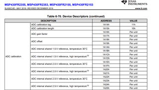
问题- #define CALADC_15V_30C (0x1A1A)和 #define CALADC_15V_85C (0x1A1C)的存储器地址值是否正确? 数据表中没有完全像写入的那些值、 我想这些值是 CAL_ADC_15T30和 CAL_ADC_15T85、它们的存储器偏移地址为0x8和0xB。
提前感谢。
理查德
/* --COPYRIGHT--,BSD_EX
 * Copyright (c) 2018, Texas Instruments Incorporated
 * All rights reserved.
 *
 * Redistribution and use in source and binary forms, with or without
 * modification, are permitted provided that the following conditions
 * are met:
 *
 * *  Redistributions of source code must retain the above copyright
 *    notice, this list of conditions and the following disclaimer.
 *
 * *  Redistributions in binary form must reproduce the above copyright
 *    notice, this list of conditions and the following disclaimer in the
 *    documentation and/or other materials provided with the distribution.
 *
 * *  Neither the name of Texas Instruments Incorporated nor the names of
 *    its contributors may be used to endorse or promote products derived
 *    from this software without specific prior written permission.
 *
 * THIS SOFTWARE IS PROVIDED BY THE COPYRIGHT HOLDERS AND CONTRIBUTORS "AS IS"
 * AND ANY EXPRESS OR IMPLIED WARRANTIES, INCLUDING, BUT NOT LIMITED TO,
 * THE IMPLIED WARRANTIES OF MERCHANTABILITY AND FITNESS FOR A PARTICULAR
 * PURPOSE ARE DISCLAIMED. IN NO EVENT SHALL THE COPYRIGHT OWNER OR
 * CONTRIBUTORS BE LIABLE FOR ANY DIRECT, INDIRECT, INCIDENTAL, SPECIAL,
 * EXEMPLARY, OR CONSEQUENTIAL DAMAGES (INCLUDING, BUT NOT LIMITED TO,
 * PROCUREMENT OF SUBSTITUTE GOODS OR SERVICES; LOSS OF USE, DATA, OR PROFITS;
 * OR BUSINESS INTERRUPTION) HOWEVER CAUSED AND ON ANY THEORY OF LIABILITY,
 * WHETHER IN CONTRACT, STRICT LIABILITY, OR TORT (INCLUDING NEGLIGENCE OR
 * OTHERWISE) ARISING IN ANY WAY OUT OF THE USE OF THIS SOFTWARE,
 * EVEN IF ADVISED OF THE POSSIBILITY OF SUCH DAMAGE.
 *
 *******************************************************************************
 *
 *                       MSP430 CODE EXAMPLE DISCLAIMER
 *
 * MSP430 code examples are self-contained low-level programs that typically
 * demonstrate a single peripheral function or device feature in a highly
 * concise manner. For this the code may rely on the device's power-on default
 * register values and settings such as the clock configuration and care must
 * be taken when combining code from several examples to avoid potential side
 * effects. Also see www.ti.com/grace for a GUI- and www.ti.com/msp430ware
 * for an API functional library-approach to peripheral configuration.
 *
 * --/COPYRIGHT--*/
//******************************************************************************
//  MSP430FR235x Demo - ADC, Sample A12 Temp and Convert to oC and oF
//
//  Description: This example works on Single-Channel Single-Conversion Mode.
//  A single sample is made on A12 (temperature) with reference to
//  internal 1.5V Vref. Software sets ADCSC to start sample and conversion
//  periodically
//  - ADCSC automatically cleared at EOC. ADC internal oscillator times
//  sample and conversion. In Mainloop MSP430 waits in LPM3 to save power until
//  ADC conversion complete, ADC12_ISR will convert the result to oC and oF
//
//  ACLK = default REFO ~32768Hz, MCLK = SMCLK = default DCODIV ~1MHz.
//
//  Uncalibrated temperature measured from device to device will vary due to
//  slope and offset variance from device to device - please see datasheet.
//
//  This code example show how to use the TLV calibrated data to measure temperature.
//  This code example is for industrial temperature device which operating temperature range is -40oC ~ +85oC.
//  For extended temperature device (-40oC ~ +105oC), ADC calibration result is for 105oC - please see datasheet.
//
//                MSP430FR2355
//             -----------------
//         /|\|                 |
//          | |                 |
//          --|RST              |
//            |                 |
//        >---|A12(temp)        |
//
//
//   Winter Yu
//   Texas Instruments Inc.
//   April. 2018
//   Built with IAR Embedded Workbench v7.10 & Code Composer Studio v7.2
//******************************************************************************
#include <msp430.h>

#define CALADC_15V_30C  *((unsigned int *)0x1A1A)                 // Temperature Sensor Calibration-30 C
                                                                  // See device datasheet for TLV table memory mapping
#define CALADC_15V_85C  *((unsigned int *)0x1A1C)                 // Temperature Sensor Calibration-High Temperature (85 for Industrial, 105 for Extended)

int main(void)
{
    WDTCTL = WDTPW | WDTHOLD;                                     // Stop WDT

    TB0CCTL0 |= CCIE;                                             // TBCCR0 interrupt enabled
    TB0CCR0 = 65535;
    TB0CTL = TBSSEL__ACLK | MC__UP;                               // ACLK, UP mode

    // Configure ADC - Pulse sample mode; ADCSC trigger
    ADCCTL0 |= ADCSHT_8 | ADCON;                                  // ADC ON,temperature sample period>30us
    ADCCTL1 |= ADCSHP;                                            // s/w trig, single ch/conv, MODOSC
    ADCCTL2 &= ~ADCRES;                                           // clear ADCRES in ADCCTL
    ADCCTL2 |= ADCRES_2;                                          // 12-bit conversion results
    ADCMCTL0 |= ADCSREF_1 | ADCINCH_12;                           // ADC input ch A12 => temp sense
    ADCIE |=ADCIE0;                                               // Enable the Interrupt request for a completed ADC_B conversion

    // Configure reference
    PMMCTL0_H = PMMPW_H;                                          // Unlock the PMM registers
    PMMCTL2 |= INTREFEN | TSENSOREN;                              // Enable internal reference and temperature sensor
    __delay_cycles(400);                                          // Delay for reference settling

    __bis_SR_register(LPM0_bits | GIE);                           // LPM0 with interrupts enabled
    __no_operation();                                             // Only for debugger
}


// ADC interrupt service routine
#if defined(__TI_COMPILER_VERSION__) || defined(__IAR_SYSTEMS_ICC__)
#pragma vector=ADC_VECTOR
__interrupt void ADC_ISR(void)
#elif defined(__GNUC__)
void __attribute__ ((interrupt(ADC_VECTOR))) ADC_ISR (void)
#else
#error Compiler not supported!
#endif
{
    volatile float temp;
    volatile float IntDegF;
    volatile float IntDegC;

    switch(__even_in_range(ADCIV,ADCIV_ADCIFG))
    {
        case ADCIV_NONE:
            break;
        case ADCIV_ADCOVIFG:
            break;
        case ADCIV_ADCTOVIFG:
            break;
        case ADCIV_ADCHIIFG:
            break;
        case ADCIV_ADCLOIFG:
            break;
        case ADCIV_ADCINIFG:
            break;
        case ADCIV_ADCIFG:
            temp = ADCMEM0;
            // Temperature in Celsius
            // The temperature (Temp, C)=
            IntDegC = (temp-CALADC_15V_30C)*(85-30)/(CALADC_15V_85C-CALADC_15V_30C)+30;

            // Temperature in Fahrenheit
            // Tf = (9/5)*Tc | 32
            IntDegF = 9*IntDegC/5+32;
            //__bic_SR_register_on_exit(LPM3_bits);               // Exit LPM3

            break;
        default:
            break;
    }
}

// Timer B0 interrupt service routine
#if defined(__TI_COMPILER_VERSION__) || defined(__IAR_SYSTEMS_ICC__)
#pragma vector = TIMER0_B0_VECTOR
__interrupt void Timer_B (void)
#elif defined(__GNUC__)
void __attribute__ ((interrupt(TIMER0_B0_VECTOR))) Timer_B (void)
#else
#error Compiler not supported!
#endif
{
    ADCCTL0 |= ADCENC | ADCSC;                                    // Sampling and conversion start
}