请注意,本文内容源自机器翻译,可能存在语法或其它翻译错误,仅供参考。如需获取准确内容,请参阅链接中的英语原文或自行翻译。
器件型号:MSP430FR2433 工具与软件:
大家好!
我将通过 I2C 连接 MPU-6050加速计和 CCS811气体传感器。
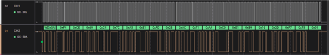
使用逻辑分析仪、在 一段时间后、UCBBUSY 被置位、且一个开始位挂起。 执行两次时、它 在请求气体传感器的数据寄存器后挂起。
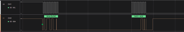
我想值得注意的是、SCL 线稍后会转换为高电平。
寄存器的写入/读取代码如下所示:
// Wake up the MPU-6050
slaveAddress = MPU_ADDR;
TX_Data[1] = PWR_MGMT_1;
TX_Data[0] = 0x08;      // Set 8 MHz clock; disable temperature sensor
TX_ByteCtr = 2;
i2c_wr(slaveAddress);
__delay_cycles(50000); // According to datasheet, hold ~30 ms
                       // Because of gyroscope based clock oscillator
slaveAddress = CCS811_ADDR;         // Make transition from boot to application mode
TX_Data[0] = CCS811_APP_START;
TX_ByteCtr = 1;
i2c_wr(slaveAddress);
__delay_cycles(30000);

slaveAddress = CCS811_ADDR;
TX_Data[1] = CCS811_MEAS_MODE;
TX_Data[0] = 0x10;                  // Put CCS to normal mode, no interrupt enable
TX_ByteCtr = 2;
i2c_wr(slaveAddress);
__delay_cycles(15000);

while(1)
{
    // Register pointing
    slaveAddress = MPU_ADDR;
    TX_Data[0] = ACCEL_XOUT_H;          // First address of the set
    TX_ByteCtr = 1;
    i2c_wr(slaveAddress);

    // Read six bytes of data
    slaveAddress = MPU_ADDR;
    RX_ByteCtr = 6;
    i2c_rd(slaveAddress);

    xAccel  = RX_Data[5] << 8 | RX_Data[4];
    yAccel  = RX_Data[3] << 8 | RX_Data[2];
    zAccel  = RX_Data[1] << 8 | RX_Data[0];
    //--------------------------------------------------------------------------------//
    __delay_cycles(50000);
    //--------------------------------------------------------------------------------//
    slaveAddress = CCS811_ADDR;
    TX_Data[0] = CCS811_ALG_RESULT_DATA;
    TX_ByteCtr = 1;
    i2c_wr(slaveAddress);
    // Reading operation of environment data register
    slaveAddress = CCS811_ADDR;
    RX_ByteCtr = 8;
    i2c_rd(slaveAddress);

    co2Lvl = (RX_Data[0] << 8 | RX_Data[1]);
    tvocLvl = (RX_Data[2] << 8 | RX_Data[3]);

    __delay_cycles(100000);
} //End while
寄存器 地址可从相应的器件数据表中提取。
作为参考、I2C 相关代码如下所示:
/**
 * Configuration of I2C module
 */
void i2c_conf(void)
{
    // I2C pins configuration
    P1SEL0 |= BIT2 | BIT3;

    // Disable the GPIO power-on default high-impedance mode to activate
    // previously configured port settings
    PM5CTL0 &= ~LOCKLPM5;

    // Configure USCI_B0 for I2C mode
    UCB0CTL1 |= UCSWRST;                    // Software reset enabled
    UCB0CTLW0 |= UCMODE_3 | UCMST;          // I2C mode, Master mode, SMCLK
    UCB0CTLW0 |= UCSSEL__SMCLK | UCSYNC;    // Use SMCLK as clock source, sync
    UCB0CTLW1 |= UCASTP_2;                  // Automatic stop generated by
                                            // reaching data acquisition boundary
    UCB0BR0 = 0x0008;                       // baudrate = SMCLK / 8 = ~100 kHz
    UCB0CTL1 &= ~UCSWRST;                   // Disable SW reset
}
/**
 * Write function
 */
void i2c_wr(unsigned char addr)
{
    while(UCB0CTL1 & UCTXSTP);          // Ensure stop condition sent

    UCB0CTL1 |= UCSWRST;
    UCB0I2CSA = addr;                   // Slave address
    UCB0TBCNT = TX_ByteCtr;
    UCB0CTL1 &= ~UCSWRST;
    UCB0IE |= UCTXIE | UCRXIE | UCBCNTIE;    // Enable Tx, RX and
                                             // byte count interruptions
    UCB0CTL1 |= UCTR;        // Transmitter mode
    UCB0CTL1 |= UCTXSTT;     // and send START condition

    __bis_SR_register(LPM0_bits|GIE);   // Enter LPM0 w/ interrupt
}
/**
 * Read function
 */
void i2c_rd(unsigned char addr)
{
    while(UCB0CTL1 & UCTXSTP);          // Ensure stop condition sent

    UCB0CTL1 |= UCSWRST;
    UCB0I2CSA = addr;                   // Slave address
    UCB0TBCNT = RX_ByteCtr;
    UCB0CTL1 &= ~UCSWRST;
    UCB0IE |= UCTXIE | UCRXIE | UCBCNTIE;              // Enable Tx and RX interruptions

    UCB0CTL1 &= ~UCTR;                  // Receiver mode
    UCB0CTL1 |= UCTXSTT;               // and send START condition

    __bis_SR_register(LPM0_bits|GIE);   // Enter LPM0 w/ interrupt
}
/**
 * UCB0 ISR
 */
#if defined(__TI_COMPILER_VERSION__) || defined(__IAR_SYSTEMS_ICC__)
#pragma vector = USCI_B0_VECTOR
__interrupt void USCIB0_ISR(void)
#elif defined(__GNUC__)
void __attribute__ ((interrupt(USCI_B0_VECTOR))) USCIB0_ISR (void)
#else
#error Compiler not supported!
#endif
{
  switch(__even_in_range(UCB0IV, USCI_I2C_UCBIT9IFG))
  {
    case USCI_I2C_UCRXIFG0:
            if (RX_ByteCtr--)
            {
                RX_Data[RX_ByteCtr] = UCB0RXBUF;  // Get received byte
            }
            break;
    case USCI_I2C_UCTXIFG0:
            if (TX_ByteCtr--)               // TRUE if more bytes remain
            {
                UCB0TXBUF = TX_Data[TX_ByteCtr];  // Load TX buffer
            }
        break;
    case USCI_I2C_UCBCNTIFG:
        __bic_SR_register_on_exit(CPUOFF);  // Exit LPM0
        break;
  }
}
感谢任何帮助。