

请注意,本文内容源自机器翻译,可能存在语法或其它翻译错误,仅供参考。如需获取准确内容,请参阅链接中的英语原文或自行翻译。
器件型号:MSP430FR5969 工具与软件:
主代码:
void main(void)
{
    //Init similiar to receive example for MSP430 FR5969
    init_I2C();

    while(1){
        cmd_process();
    }

}
init_i2C():
void init_I2C(){
WDT_A_hold(WDT_A_BASE);
// Configure Pins for I2C
//Set P1.6 and P1.7 as Secondary Module Function Input.
/*
* Select Port 1
* Set Pin 6, 7 to input Secondary Module Function, (UCB0SIMO/UCB0SDA, UCB0SOMI/UCB0SCL).
*/
GPIO_setAsPeripheralModuleFunctionInputPin(
GPIO_PORT_P1,
GPIO_PIN6 + GPIO_PIN7,
GPIO_SECONDARY_MODULE_FUNCTION
);
/*
* Disable the GPIO power-on default high-impedance mode to activate
* previously configured port settings
*/
PMM_unlockLPM5();
// eUSCI configuration
EUSCI_B_I2C_initSlaveParam param = {0};
param.slaveAddress = SLAVE_ADDRESS;
param.slaveAddressOffset = EUSCI_B_I2C_OWN_ADDRESS_OFFSET0;
param.slaveOwnAddressEnable = EUSCI_B_I2C_OWN_ADDRESS_ENABLE;
EUSCI_B_I2C_initSlave(EUSCI_B0_BASE, ¶m);
EUSCI_B_I2C_enable(EUSCI_B0_BASE);
EUSCI_B_I2C_clearInterrupt(EUSCI_B0_BASE,
EUSCI_B_I2C_RECEIVE_INTERRUPT0 + EUSCI_B_I2C_TRANSMIT_INTERRUPT0 + EUSCI_B_I2C_STOP_INTERRUPT
);
EUSCI_B_I2C_enableInterrupt(EUSCI_B0_BASE,
EUSCI_B_I2C_RECEIVE_INTERRUPT0 + EUSCI_B_I2C_TRANSMIT_INTERRUPT0 + EUSCI_B_I2C_STOP_INTERRUPT
);
// __bis_SR_register(CPUOFF + GIE); // Enter LPM0 w/ interrupts
// __no_operation();
}
CMD_PROCESS():
void cmd_process() {

    switch(current_Statemachine) {
        case IDLE:
            resumeI2CInterrupts();
            break;
        case HEALTH_CHECK: // Simply Returns the received data

            TXData = myPayload;
            current_Statemachine = IDLE;
            break;
... Rest of the code
Arduino 主代码(teensy):
#include <Wire.h>

byte arrToSend[] = {
  'a', 'b', 'c', 'd', 'e', 'f', 'g', 'h', 'i', 'j',
  'k', 'l', 'm', 'n', 'o', 'p', 'q', 'r', 's', 't',
  'u', 'v', 'w', 'x', 'y', 'z'
};

void test_health_check(int numofBytes)
{
    Wire.beginTransmission(0x08); // Address of the MSP430 slave
    Wire.write(0x22);
    int i;
    for(i = 0; i<numofBytes; i++)
    {
      Wire.write(arrToSend[i]);
    }
    Wire.endTransmission();

    delay(1000);

    Wire.requestFrom(0x08, ++numofBytes);

    Serial.write("Receiving ");
    Serial.print(numofBytes);
    Serial.write(" byte(s):");
    while(Wire.available()) {
        char c = Wire.read();    // Receive a byte
        Serial.write(" ");
        Serial.write(c);         // Print the character
        numofBytes--;
        if(numofBytes == 0) break;
    }
    Serial.write("\n");
}

void setup() {
    Wire.begin(); // Join the I2C bus as a master
    Serial.begin(9600);

    int i;
    for(i = 0; i < 10; i++)
      test_health_check(i);

}

void loop() {
    int i;
    for(i = 0; i < 10; i++)
    {
      delay(2000);
      test_health_check(i);
    }
}
问题发生在哪里
ISR:
void suspendI2CInterrupts() {
    EUSCI_B_I2C_disableInterrupt(EUSCI_B0_BASE,
         EUSCI_B_I2C_RECEIVE_INTERRUPT0 + EUSCI_B_I2C_TRANSMIT_INTERRUPT0 + EUSCI_B_I2C_STOP_INTERRUPT
         );
}

void resumeI2CInterrupts() {
    EUSCI_B_I2C_enableInterrupt(EUSCI_B0_BASE,
        EUSCI_B_I2C_RECEIVE_INTERRUPT0 + EUSCI_B_I2C_TRANSMIT_INTERRUPT0 + EUSCI_B_I2C_STOP_INTERRUPT
        );
    __bis_SR_register(CPUOFF + GIE); // Enter LPM with interrupts
}


#if defined(__TI_COMPILER_VERSION__) || defined(__IAR_SYSTEMS_ICC__)
#pragma vector=USCI_B0_VECTOR
__interrupt
#elif defined(__GNUC__)
__attribute__((interrupt(USCI_B0_VECTOR)))
#endif
void USCIB0_ISR(void)
{

//    static uint8_t * incoming_Data = myPayload;
    static uint8_t incoming_data_index = 0;
    static uint8_t rcving_Data = 0;

    switch(__even_in_range(UCB0IV, USCI_I2C_UCBIT9IFG))
    {
        case USCI_NONE:             // No interrupts break;
            break;
        case USCI_I2C_UCALIFG:      // Arbitration lost
            break;
        case USCI_I2C_UCNACKIFG:    // NAK received (master only)
            break;
        case USCI_I2C_UCSTTIFG:     // START condition detected with own address (slave mode only)

            break;
        case USCI_I2C_UCSTPIFG:     // STOP condition detected (master & slave mode)

            incoming_data_index = 0;
            if (rcving_Data==1){
                rcving_Data = 0;
                cmd_receive();
            }

            break;
        case USCI_I2C_UCRXIFG3:     // RXIFG3
            break;
        case USCI_I2C_UCTXIFG3:     // TXIFG3
            break;
        case USCI_I2C_UCRXIFG2:     // RXIFG2
            break;
        case USCI_I2C_UCTXIFG2:     // TXIFG2
            break;
        case USCI_I2C_UCRXIFG1:     // RXIFG1
            break;
        case USCI_I2C_UCTXIFG1:     // TXIFG1
            break;
        case USCI_I2C_UCRXIFG0:     // RXIFG0
//            suspendI2CInterrupts(); // Commenting this allowed us to send data the case "USCI_I2C_UCTXIFG0"
            __bic_SR_register_on_exit(CPUOFF);

            RXData = EUSCI_B_I2C_slaveGetData(EUSCI_B0_BASE);
//            if (RXData == 0x01){
//                GPIO_setAsOutputPin(GPIO_PORT_P1, GPIO_PIN0);
//
//                GPIO_setOutputHighOnPin(GPIO_PORT_P1, GPIO_PIN0);
//            }else if (RXData == 0x02){
//                GPIO_setAsOutputPin(GPIO_PORT_P1, GPIO_PIN0);
//
//                GPIO_setOutputLowOnPin(GPIO_PORT_P1, GPIO_PIN0);
//            }

//            *incoming_Data = RXData;
//            incoming_Data++;
            myPayload[incoming_data_index++] = RXData;
            rcving_Data = 1;

            break;
        case USCI_I2C_UCTXIFG0:     // TXIFG0
            __bic_SR_register_on_exit(CPUOFF);

            EUSCI_B_I2C_slavePutData(EUSCI_B0_BASE,
                *TXData
                );
            TXData++;

            break;
        case USCI_I2C_UCBCNTIFG:    // Byte count limit reached (UCBxTBCNT)
            break;
        case USCI_I2C_UCCLTOIFG:    // Clock low timeout - clock held low too long
            break;
        case USCI_I2C_UCBIT9IFG:    // Generated on 9th bit of a transmit (for debugging)
            break;
        default:
            break;
    }
}
如果我发送4个字节、
对于前三个字节、运行"USCI_I2C_UCRXIFG0"情形、
然后运行停止条件情况"USCI_I2C_UCSTPIFG"
然后处理最后一个字节并运行"USCI_I2C_UCRXIFG0"情形、即使该情形应该在停止条件之前发生也是如此。


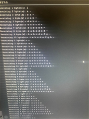
忽略串行输出中的第一个运行、后续运行会重写第一个索引、因为停止条件始终在处理最后一个字节之前执行、打印的第一个字节应为"0x22"。
我使用5.5k 欧姆的上拉、MSP430提供3.6V 的 VCC。
MSP430是从器件、Arduino Teensy 是主器件。
